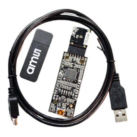
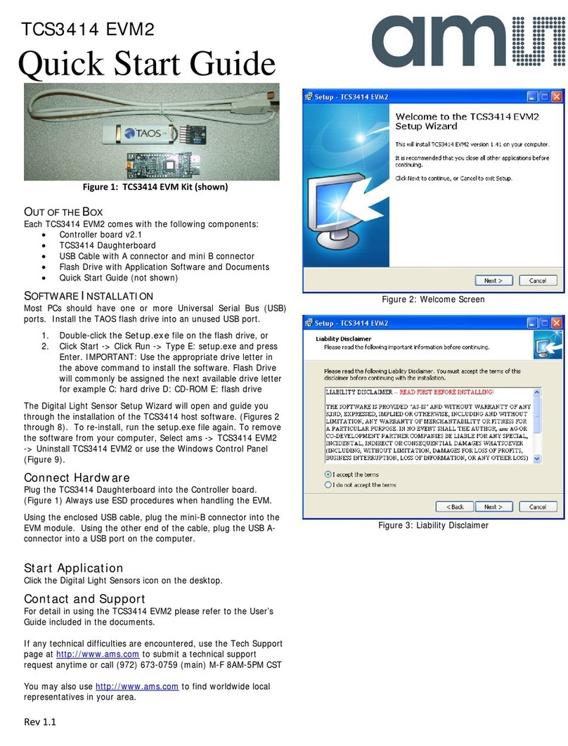
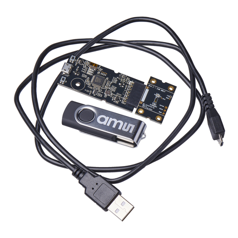
AMS OSRAM NanEye User manual

Product
Document
Published by
ams OSRAM Group

Document Feedback
NanEye
Content Guide
Eval Kit Manual •PUBLIC
UG001036 •v3-00 • 2022-May-31
43 │2
Content Guide
1Introduction ................................... 3
1.1 Ordering Information ....................................3
2Hardware Description ................... 4
2.1 Fiber Optic Box 2.0.......................................4
2.2 NanoUSB2.2...............................................13
3NanEye Viewer Software............. 20
3.1 General Description....................................20
3.2 Software Installation...................................20
3.3 Start the Application ...................................23
3.4 Common Issues..........................................38
4Schematics and Source Code ....41
5Revision Information...................42
6Legal Information.........................43

Document Feedback
NanEye
Introduction
Eval Kit Manual •PUBLIC
UG001036 •v3-00 • 2022-May-31
43 │3
1 Introduction
NanEye is a family of miniature sized image sensors for vision applications where size is a critical
factor. The ability of the camera head to drive a signal through long cables makes this the ideal
component for minimal diameter endoscopes.
The sensor has been specially designed for medical endoscopic applications where high SNR is
mandatory. The sensor includes a 10-bit ADC and a bit serial LVDS data interface. The sensors are
able to drive the signal through a cable length of up to 3 m.
The data line is semi duplex, such that configuration can be communicated to the sensor in the frame
brake. The exposure time, dark level, analog gain and frame rate can be programmed over the serial
configuration interface.
The Fiber Optic Box and NanoUSB2 evaluation kits are able to communicate with the NanEye
sensors. The NanEye Viewer software enables the user to send the sensor register values, as well as
grab the RAW images to store or add image processing. Additional features are referred along the
document.
Information
For more information about the NanEye family specifications, please see its datasheets on the
webpage.
1.1 Ordering Information
Ordering Code
Description
NANO_FIB_BOX_2.0
Fiber Optic Box 2.0 Evaluation Kit(1)
NANOUSB2.2
NanoUSB2.2 Evaluation Kit(1)
(1) Please note that the sensors do not come with the Evaluation Kit. The sensors need to be ordered separately, according
to each respective ordering code, in the respective NanEye datasheets.

Document Feedback
NanEye
Hardware Description
Eval Kit Manual •PUBLIC
UG001036 •v3-00 • 2022-May-31
43 │4
2 Hardware Description
2.1 Fiber Optic Box 2.0
2.1.1 Out of the Box
NanEye Fiber Optic Box 2.0 (FOB2.0) is a fully embedded all in one image processing unit that
interfaces the NanEye® micro camera head signals and provides an output of 1080p/60 format HDMI
video signal which can be directly plugged to a HDMI compatible monitor, which in this mode no
additional PC or image processing is required.
The USB3 interface allows the connection to the NanEye Viewer running on a PC to get access to the
sensor’s raw images and control settings.
The main body of the demo kit measures only 17 cm x 17 cm x 5.6 cm and provides all necessary
video processing and display driving plus the adjustable illumination.
Figure 1:
Fiber Optic Box 2.0 Demo Kit
Attention
The Fiber Optic Box 2.0 Demo Kit is intended solely for evaluation purposes, has no EMI approval
and is not advisable for medical use. ams OSRAM therefore is not liable for any damage or harm
resulting from its use.

Document Feedback
NanEye
Hardware Description
Eval Kit Manual •PUBLIC
UG001036 •v3-00 • 2022-May-31
43 │5
Figure 2:
Fiber Optic Box 2.0 Benefits/Features
Benefits
Features
Easy to use plug and play solution
Supports up to two NanEye®2D, XS and M
Stand alone video output via HDMI (no PC
required)
Integrated adjustable current source for
illumination
High quality image output
HDMI 1080p/60 video output
All-in-one eval kit with illumination
USB3 PC interface to NanEye Viewer
Raw image data access and sensor control via
USB3 and NanEye Viewer
Image processing, correction and
enhancements
Figure 3:
Fiber Optic Box 2.0 Pinout Description
Front Side
Rear Side
JST Connector
HDMI Output
●2 x NanEye2D/M/XS
●1080P60 to display NanEye
●1 x Current source up to 22.7 mA (channel 1)
●No additional PC needed
Rotary Switch
USB3.0
●Light mode and intensity control
●Display NanEye channel 1 & 2 with NanEye
Viewer software
Adjust light intensity of distal LED ring
Adjust image processing
Dual Color Status LED
LEMO Connector
Power Supply
●Do not use
12 V DC, 1.5 A minimum
Attention
Do not connect the NanEye2D simultaneously with NanEyeM or NanEyeXS. NanEye2D works with
a lower voltage range than NanEyeXS and NanEyeM. A higher voltage on NanEye2D will cause
irreversible damage to the sensor. Also do not connect a NanEyeXS simultaneously with NanEyeM.

Document Feedback
NanEye
Hardware Description
Eval Kit Manual •PUBLIC
UG001036 •v3-00 • 2022-May-31
43 │6
2.1.2 Plug and Play
Recommended Connection
The following image shows the necessary equipment for a direct connection to a monitor.
Figure 4:
Fiber Optic Box Plug and Play Equipment Connection
1. Firstly connect the NanEye module to the box
2. Then connect the box to the monitor using a HDMI cable
3. Plug in the 12 V DC power adapter and wait for the Fiber Optic Box to power up
Fiber Optic Box Operation
●Dual Color Status LED
●Constant Green → Status ok, no sensor connected, test pattern output via HDMI
●Blinking Green → Sensor data transmission, sensor is working successfully
●Blinking Amber (pulse > 1 second) → at least one error during sensor data decoding
detected
●Blinking Amber (pulse < 250 ms) → Flash programming (more details on section 2.1.4)

Document Feedback
NanEye
Hardware Description
Eval Kit Manual •PUBLIC
UG001036 •v3-00 • 2022-May-31
43 │7
Figure 5:
Fiber Optic Box Rotary Switch
Rotary Switch
Push Button
Rotate
Action
Function
Function
Default Mode
Press during one second
White balance optimized
for fiber light color
temperature(1)
Adjusts light intensity(1)
Optimized white balance
for LED ring color
temperature(2)
Adjusts light intensity
Neutral color temperature.
No tuning of white
balance
N/A
User Mode
Double click
Histogram Stretching
Mode
On/Off
Additional Long Press
White Balance Mode
Default Values/ Keep
Values / Calibration
Additional Long Press
Back to Histogram
Stretching Mode
On/Off
Double click
Back to Default Mode
Depends on chosen
function
(1) NanEye2D with fiber illumination is a discontinued product. Moreover, the latest FOB version no longer have the fiber
optic hardware. The illumination feature only works for previous versions of the FOB.
(2) NanEye2D version with LED ring is a discontinued product.
When entering the User Mode for White Balancing:
●Keep Values: no changes relative to the White Balance set previously. This is for the case the
'White Balance' menu is entered the but actually is not intended to modify the current settings
●Default Values: sets the default values, i.e. 1.0 for RGB in case of no illumination, LED
dependent in case of illumination
●Calibrating: shows a ROI into which the white target has to be placed. Calibration is performed
in real time, so the results will be seen immediately. It can be set back to 'keep values', or exit
the menu by a long press or exit user mode by a double click. To calibrate properly, please
point the sensor to a white surface/object (homogeneous illumination)
Image Viewing
The following image shows the Fiber Optic Box layout on the monitor. The coloured screensaver
represents the mode when there is no NanEye module connected, where the status LED is constant
green. In the bottom left corner it is possible to observe the hardware and firmware version.

Document Feedback
NanEye
Hardware Description
Eval Kit Manual •PUBLIC
UG001036 •v3-00 • 2022-May-31
43 │8
Figure 6:
Fiber Optic Box Plug and Play Layout
2.1.3 Operation with PC
Recommended Connection
The following image shows the necessary equipment for a direct connection to a PC.
Figure 7:
Fiber Optic Box NanEye Viewer Equipment Connection

Document Feedback
NanEye
Hardware Description
Eval Kit Manual •PUBLIC
UG001036 •v3-00 • 2022-May-31
43 │9
Please take the following steps to perform the correct connection:
1. Please ensure that the NanEye Viewer software has been correctly installed, refer to section
3.2.
2. Plug the USB3 type A cable to the Fiber Optic Box and the PC.
3. Plug in the 12 V DC power adapter and wait for the Fiber Box to power up.
4. Wait for it to be automatically recognized. Please check on the Device Manager if your device
is recognized as Cypress FX3 USB StreamerExample Device as shown in Figure 8.
5. Connect the sensor to the respective port and wait for the green LED to be blinking.
6. The NanEye Viewer can be started choosing the Camera, Board and Viewer, following the
suitable combination available on Figure 31. If the board is not recognised correctly please
check next sections Installing FX3 Driver Manually and How to Debug Fiber Optic Box.
Figure 8:
Fiber Optic Box Device Connection
Installing FX3 Driver Manually
If the driver is not correctly installed after installing NanEye Viewer, please go to:
●Program Files (x86)\ams OSRAM\NanEye Viewer vx.x.x.x\driver\FX3_Driver
Then, according to the operating system, run the respective Drive Package Installer (dpinst_x86/x64).

Document Feedback
NanEye
Hardware Description
Eval Kit Manual •PUBLIC
UG001036 •v3-00 • 2022-May-31
43 │10
How to Debug Fiber Optic Box
If the NanEye Viewer does not run, this section can help to debug the board.
When the NanEye Viewer is installed, the programs included inside the folder Program Files
(x86)\ams OSRAM\NanEye Viewer vx.x.x.x\application\debug\Usb3, can be used to debug any
occurring issues.
In order to reprogram the FPGA, start FPGA Configuration Utility (Template.exe), follow the
instructions on that window and use the .bin file (for instance, fob_fpga_vxx.bin). This .bin file can be
found at C:\ProgramData\ams OSRAM\NanEye Viewer\Fpga Files\NanEye_USB3.
When this task is completed, the information is displayed as below. This means that the FPGA is
programming correctly.
Figure 9:
Fiber Optic Box FPGA Configuration
If the NanEye Viewer still does not open, please reinstall the software.
Information
If the issues are still not solved, please contact the Technical Support team.
2.1.4 Permanent Flash Programming
From production, the FOB already comes with a firmware stored in the flash, in order to use Plug and
Play mode. However, there may be a need to update to use the new features.
There are different ways to program the FOB2.0. One way is to use procedure on step 6 of
Recommended Connection section. The drawback of this solution is that, as soon as the system is
power cycled, it returns to the previous firmware in the flash, therefore a temporary solution.

Document Feedback
NanEye
Hardware Description
Eval Kit Manual •PUBLIC
UG001036 •v3-00 • 2022-May-31
43 │11
To permanently store the programming file in the flash, it can be done via JTAG. However, this
procedure is not so elegant at user’s side, once the box needs to be opened.
To overcome this situation, the system was upgraded to permanently program the flash via USB3.
This procedure is performed via NanEye Viewer Software (only available from version v6.3.x.x on).
The user needs to choose the Board as FiberOpticBox_USB3 and, in the Viewer section, will show
“ProgramFlash”, independently of the Camera chosen. Before initiating this process, please make
sure that the FOB is connected to both power supply and USB3 port.
Figure 10:
Flash Programming –NanEye Viewer Layout
Information
This process can be done with or without a HDMI screen connected. However, is recommended to
use a monitor to easily follow and observe the programming steps.
After pressing “Load Default Configuration”, the programming section will show as Figure 11. Please
click on the three dots box on the most right and it will automatically open the respective folder to
upload the firmware. Please make sure to choose the latest fob_fpga_vXX.bin file.

Document Feedback
NanEye
Hardware Description
Eval Kit Manual •PUBLIC
UG001036 •v3-00 • 2022-May-31
43 │12
Figure 11:
Programming Layout Folder Directory
After choosing the respective programming file, the user can Start the programming, as show below.
This step basically transfers the file into the FOB.
Figure 12:
Programming File Upload Process
Once the programming data is transferred to the EVK, the NanEye Viewer will notify to disconnect the
USB3 cable, as shown below. Click OK and the NanEye Viewer will close. Simultaneously, the same
notification is shown on the monitor. Also note that the FOB LED will be blinking with amber color and
it will maintain this state until the end of the full programming.
Figure 13:
USB3 Disconnection Step –NanEye Viewer
Figure 14:
USB3 Disconnection Step –HDMI Monitor

Document Feedback
NanEye
Hardware Description
Eval Kit Manual •PUBLIC
UG001036 •v3-00 • 2022-May-31
43 │13
After disconnecting the USB3 cable, the system will start to erase the flash, which can take up to two
minutes. Right after, it will start flash programming, as shown below.
Figure 15:
Flash Erasing
Figure 16:
Flash Programming
Once programmed, to conclude the process it will perform a flash verification. Finally, the flash update
is finished. As the programming is done, the LED becomes constant green. Now the user can now
power cycle the system, to then observe the layout as in Figure 6.
Figure 17:
Flash Verification
Figure 18:
Programming Done –Power Cycle
2.2 NanoUSB2.2
2.2.1 Out of the Box
The NanoUSB2 demo kit is the ideal basis for customers that intent to develop a video processing
engine. It is the hardware between the camera and the PC and it does the deserialisation of the data
stream that comes from the NanEye® camera. It allows to control one NanEye2D camera along with

Document Feedback
NanEye
Hardware Description
Eval Kit Manual •PUBLIC
UG001036 •v3-00 • 2022-May-31
43 │14
the LED illumination, if available on the camera module. The base station is powered over the USB
port, 5 V supply, and creates a regulated power supply for the sensor.
Figure 19:
NanoUSB2 Specifications
Specifications
Programmable unit
FPGA –Xilinx Spartan 3D
Power supply
Via USB 5 V
Housing dimensions
5.8 cm x 3.7 cm x 1.4 cm
Board dimensions
5.2 cm x 3.04 cm
LED supply
12-bit DAC, 50 mA max @16 V max –
Controlled FPGA register
Attention
The NanoUSB2 Demo Kit is intended solely for evaluation purposes, has no EMI approval and is
not advisable for medical use. ams OSRAM therefore is not liable for any damage or harm resulting
from its use.
2.2.2 Operation with PC
Recommended Connection
The following image shows the necessary equipment for a direct connection to a PC.

Document Feedback
NanEye
Hardware Description
Eval Kit Manual •PUBLIC
UG001036 •v3-00 • 2022-May-31
43 │15
Figure 20:
NanoUSB2 Demo Kit Connection Material
The NanEye2D sensor FlexPCB connector should be connected as shows in Figure 21, where the
pcb tracks and epoxy are facing outwards the NanoUSB2.
Figure 21:
NanEye2D Sensor Placed On NanoUSB2 Connector

Document Feedback
NanEye
Hardware Description
Eval Kit Manual •PUBLIC
UG001036 •v3-00 • 2022-May-31
43 │16
Please take the following steps to perform the correct connection:
1. Please check if the NanEye Viewer software has been correctly installed, refer to section 3.2
2. Plug the sensor male connector in the NanoUSB2 female connector as in Figure 21
3. Plug the USB2 type mini-B connector to the NanoUSB2 and the end USB type A to the PC
4. Wait for it to be automatically recognized. Please check on Device Manager if your device is
recognized as Cesys USB Device (NANOUSB) as shown in Figure 22
Figure 22:
NanoUSB2 Device Connection to PC
Installing Cesys Drivers Manually
If in Device Manager, the NanoUSB2.2 is not recognized in Figure 22 and shows:
●Cesys Device (NANOUSB, loading stage…) → Install or reinstall the driver (udk3usb-drivers-
windows-1.3)
●Go to C:\Program Files (x86)\ams OSRAM\NanEye Viewer vx.x.x.x\driver\cesys
●CeusbUni → Update the driver

Document Feedback
NanEye
Hardware Description
Eval Kit Manual •PUBLIC
UG001036 •v3-00 • 2022-May-31
43 │17
How to Debug NanoUSB2 Board
If the viewer is not programming the NanoUSB2 FPGA, please run the Board Tester program located
at C:\Program Files (x86)\ams OSRAM\NanEye Viewer vx.x.x.x\application\debug\Usb2. This will
check if there is a problem with the board or sensor.
Attention
Please make sure that, before running BoardTester.exe, the NanEye Viewer application is closed
and/or an API is not running.
After executing the program, a window like Figure 23 should appear. If the NanoUSB2.2 is well
connected and identified in Device Manager, “Devices detected” throws the value ‘1’. Otherwise, will
show a ‘0’.
Figure 23:
Board Tester Layout –NanoUSB2 Detected
The next step is to get the NanEye2D data, pressing ‘1’. The result should be as shown below, where
is received data correctly. In this case, NanEye Viewer and API should also work.

Document Feedback
NanEye
Hardware Description
Eval Kit Manual •PUBLIC
UG001036 •v3-00 • 2022-May-31
43 │18
Figure 24:
Board Tester Layout –Sensor Data Read Successfully
If the NanoUSB2.2 is correctly identified, but cannot read data from the sensor, as shown in Figure 25,
it can be a sensor related issue. Therefore, in order to find the root cause, please see below the
possible situations, such as:
●NanEye2D connector may not be placed correctly (check section Recommended Connection)
●Check Figure 21
●USB2 communication issue
●Power cycle the NanoUSB2.2
●Try a different USB port, cable or machine
●NanoUSB2.2 female connector may be damaged
●NanEye2D module may be damaged (connector/cable /sensor)
●Check NanEye2D_Module_Handling_Manual_AN000493_1-01
Table of contents
Other AMS Motherboard manuals

AMS
AMS AS5 Series User manual

AMS
AMS AS5047P-TS_EK_AB User manual

AMS
AMS AS6204 User manual

AMS
AMS TCS3414 EVM2 User manual

AMS
AMS GP30-DEV-KIT User manual

AMS
AMS TMF882X-SHIELD User manual

AMS
AMS TCS3707 EVM User manual

AMS
AMS TSL2584TSV User manual

AMS
AMS USB I&P Box User manual

AMS
AMS TSL2572 EVM User manual