Amsco Century User manual

OPERATOR MANUAL
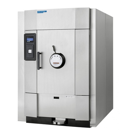
Amsco®CenturyTM
Medium Steam Sterilizer 26" x 37.5"
(04/27/11) P129373-496
Rev. 1Rev. 0

i
Table of Contents Operating Instructions 129373-496
A WORD FROM STERIS CORPORATION
A summary of the safety precautions to be observed when operating or
servicing this equipment can be found in Section 1 of this manual. Do not
operate or service the sterilizer until you have become familiar with this
information.
This sterilizer is not designed to process flammable liquids nor liquids in
containers that are not designed for sterilization. Any alteration of the sterilizer
which affects its operation will void the warranty and could violate state and
local regulations and jeopardize insurance coverage.
Advisory
This manual contains important information on proper use of the Amsco®
CenturyTM Medium Steam Sterilizer 26" X 37.5". Allpersonnelinvolvedinthe
use of this equipment must carefully review and comply with the
warnings, cautions, and instructions contained in this manual. These
instructions are important to protect the health and safety of personnel
operating an Amsco Century Medium Steam Sterilizer and should be retained
in a conveniently accessible area for quick reference.
This sterilizer is specifically designed to process goods using only the cycles
as specified in this manual. If there is any doubt about a specific material or
product, contact the manufacturer of the product for the recommended
sterilization technique.
STERIS carries a complete line of accessories for use with this sterilizer to
simplify, organize, and assure sterility of the sterilization process. Instrument
trays and biological/chemical monitoring systems are all available to fulfill
your facility's processing needs. A STERIS representative will gladly review
these with you.
A thorough preventive maintenance program is essential to safe and proper
sterilizer operation. Comprehensive instructions for routine preventive main-
tenance can be found in
Maintenance Manual, P-764330-117
, available
separately.
You are encouraged to contact STERIS concerning our Preventive Mainte-
nance Agreement. Under the terms of this agreement, preventive mainte-
nance, adjustments, and replacement of worn parts are done on a scheduled
basis to assure equipment performance at peak capability and to help avoid
untimely or costly interruptions. STERIS maintains a nationwide staff of well-
equipped, factory-trained technicians to provide this service, as well as
expert repair services. Please contact your STERIS representative for details.
Service Information
The Amsco Century Medium Steam Sterilizer is designed for efficient steriliza-
tion of non-porous and porous, heat and moisture-stabile materials. The
Amsco Century Medium Steam Sterilizer is available in the following configu-
rations:
26" x 37.5" x 36" (660 x 953 x 914 mm) Single Door Prevacuum
26" x 37.5" x 48" (660 x 953 x 1219 mm) Single Door Prevacuum
26" x 37.5" x 48" (660 x 953 x 1219 mm) Double Door Prevacuum
26" x 37.5" x 60" (660 x 953 x 1524 mm) Single Door Prevacuum
26" x 37.5" x 60" (660 x 953 x 1524 mm) Double Door Prevacuum
Indications for Use
© 2011 –STERIS Corporation. All rights reserved. Printed in U.S.A.

ii
129373-496 Operating Instructions Table of Contents
CYCLES RECOMMENDED STERILIZE STERILIZE DRY TIME
LOADS TEMP. TIME
PREVACUUM Heat and moisture-stabile 132°C 4 minutes 5 minutes
materials utilizing vacuum- (270°F)
assisted air removal process.
GRAVITY Heat and moisture-stabile 132°C 15 minutes 5 minutes
materials (270°F)
LIQUIDS Liquids and media in 121°C 45 minutes N/A
vented borosilicate glass (250°F)
containers.
The Amsco Century Medium Steam Sterilizer is equipped with the following default cycles and cycle
values (see Section 7 for detailed cycle parameters and instructions for modifying cycle parameters).
Manufactured by:
STERIS Mexico S. de R.L. de C.V.
Avenida Avante 790
Parque Industrial Guadalupe
Guadalupe, Nuevo Leon, Mexico C.P. 67190
Sales and Service:
STERIS Corporation
5960 Heisley Road
Mentor, Ohio 44060
440-354-2600 • 800-444-9009
www.steris.com
STERIS Limited
Chancery House
190 Waterside Road
Hamilton Industrial Park
Leicester
LE5 1QZ UK
The base language of this document is
ENGLISH. Any translations must be
made from the base language
document.
0086

iii
Table of Contents Operating Instructions 129373-496
TABLE OF CONTENTS
1 Listing ofWarnings and Cautions ..............................................1-1
2 InstallationVerification.................................................................2-1
2.1 Installation Checklist .......................................................................... 2-1
2.1.1 Service Clearance ...................................................................... 2-1
2.1.2 Plumbing Services ...................................................................... 2-1
2.1.3 Electrical Service ........................................................................ 2-2
2.1.4 Sterilizer Final Check.................................................................. 2-2
2.1.5 Cycle Operation ......................................................................... 2-2
2.2 Technical Specifications ..................................................................... 2-3
2.2.1 Overall Size ................................................................................ 2-3
2.2.2 Weight ........................................................................................ 2-3
2.2.3 Utility Requirements ................................................................... 2-3
2.2.4 Environmental Conditions .......................................................... 2-4
3 Techniques of Sterilization..........................................................3-1
3.1 General .............................................................................................. 3-1
3.2 Recommended Sterilization Variables ............................................... 3-1
3.2.1 Prevacuum Cycle ....................................................................... 3-1
3.2.2 Gravity Cycle ............................................................................. 3-2
3.2.3 Liquid Cycle ............................................................................... 3-2
3.3 Recommendations for Sterilizing Liquids .......................................... 3-3
3.4 Recommendations for Enhancing the Sterilization Process .............. 3-4
3.5 Control Measures for Verifying Sterilization Process ........................ 3-5
3.5.1 Biological Monitors ..................................................................... 3-5
3.5.2 Testing for Prevacuum Efficiency ............................................... 3-5
3.6 Dart (Bowie-Dick) Test ...................................................................... 3-6
3.7 Vacuum Leak Test ............................................................................. 3-6
4 Component Identification............................................................4-1
4.1 Main Power Disconnect Switch ......................................................... 4-2
4.2 Supply Valves.................................................................................... 4-2
4.3 Control Panel ..................................................................................... 4-3
4.3.1 Touch Screen ............................................................................... 4-3
4.3.2 Printer ......................................................................................... 4-4
4.4 Unload End Control Panel (Double Door Units) ................................ 4-5
4.5 Hinged-Door Operation..................................................................... 4-6
4.6 Horizontal-sliding Door Operation ..................................................... 4-7
4.7 Emergency Door Opening Procedure .............................................. 4-8
Section Description Page

iv
129373-496 Operating Instructions Table of Contents
TT
TT
T
ableofContents(continued)ableofContents(continued)
ableofContents(continued)
5 Control Interface ..........................................................................5-1
5.1 General.............................................................................................. 5-1
5.2 Cycle Select Menus .......................................................................... 5-2
5.2.1 Processing Cycles ..................................................................... 5-2
5.2.2 Test Cycles................................................................................. 5-4
5.3 Out-of-cycle Options Menus ............................................................. 5-5
6 Sterilizer Operation ......................................................................6-1
6.1 Before Operating Sterilizer ................................................................ 6-1
6.2 Loading/Unloading Sterilizer: Rack and Shelves .............................. 6-3
6.2.1 Loading Car Instructions: Loading ............................................ 6-4
6.2.2 Loading Car Instructions: Unloading ......................................... 6-5
6.3 Prevacuum Cycle Operation ............................................................. 6-5
6.4 Gravity Cycle Operation ................................................................. 6-12
6.5 Liquid Cycle Operation ................................................................... 6-18
6.6 Leak Test Cycle Operation .............................................................. 6-23
6.7 Dart®Warm-up Cycle Operation ..................................................... 6-26
6.8 Dart®Test Cycle Operation ............................................................. 6-29
6.9 Aborting Cycles .............................................................................. 6-31
7 Entering Access Code.................................................................7-1
7.1 Sterilizer Usage Locked Out ............................................................. 7-1
7.2 Change Values Menu Locked Out .................................................... 7-2
8 Programming Cycle Values .........................................................8-1
8.1 Access Cycle Menu–Change Cycle Values ..................................... 8-2
8.2 Change Values Procedure ................................................................ 8-4
9 Programming Operating Parameters .........................................9-1
9.1 Access Change Values Menu ........................................................... 9-1
9.2 Time/Date .......................................................................................... 9-2
9.3 Too Long In Phase ............................................................................. 9-4
9.4 Setup ................................................................................................. 9-8
9.4.1 Temp/Pres Units ......................................................................... 9-9
9.4.2 Audible Signals ........................................................................ 9-12
9.4.3 Utility Shutdown ....................................................................... 9-14
9.4.4 Print Format .............................................................................. 9-20
9.4.5 Duplicate Print .......................................................................... 9-22
9.4.6 Turn Off Printer ......................................................................... 9-23
Section Description Page

v
Table of Contents Operating Instructions 129373-496
TT
TT
T
ableofContents(continued)ableofContents(continued)
ableofContents(continued)
10 Out of Cycle Options..................................................................10-1
10.1 General .......................................................................................... 10-1
10.2 Status Print .................................................................................... 10-2
10.3 Duplicate Print ............................................................................... 10-3
10.4 Paper Feed .................................................................................... 10-3
10.5 Change Values .............................................................................. 10-4
10.6 Display Values ............................................................................... 10-4
10.6.1 Cycles .................................................................................... 10-5
10.6.2 Time/Date ............................................................................... 10-8
10.6.3 Too Long in Phase .................................................................. 10-9
10.6.4 Setup ...................................................................................... 10-9
10.7 Print Values .................................................................................. 10-11
10.7.1 All Values .............................................................................. 10-11
10.7.2 All Values Changed .............................................................. 10-12
10.7.3 A Particular Cycle................................................................. 10-12
10.8 Standby ....................................................................................... 10-14
10.9 Display Sensors .......................................................................... 10-15
10.10 Supervisory ............................................................................... 10-16
10.10.1 Change Customer Name ................................................... 10-18
10.10.2 Change Sterilizer ID ........................................................... 10-19
10.10.3 Default Values .................................................................... 10-20
10.10.4 Change Access Codes ..................................................... 10-20
• Change Values Access Codes ................................................. 10-20
• Sterilizer Operation Access Codes .......................................... 10-24
• Supervisory Access Code ........................................................ 10-28
10.10.5 Display Access Codes ...................................................... 10-30
10.10.6 RS-232 Interface................................................................. 10-32
10.10.7 Override Interlocks ............................................................ 10-33
10.11 Service Mode ............................................................................ 10-34
Section Description Page

vi
129373-496 Operating Instructions Table of Contents
11 Routine Maintenance.................................................................11-1
11.1 Preventive Maintenance Schedule ................................................ 11-1
11.1.1 Clean Chamber Drain Strainer ............................................... 11-3
11.1.2 Clean Chamber ...................................................................... 11-3
11.2 Weekly Maintenance ..................................................................... 11-4
11.2.1 Flush Chamber Drain ............................................................. 11-4
11.2.2 Change Printer Paper Roll ...................................................... 11-5
11.2.3 Change Printer Ink Cartridge ................................................. 11-7
11.3 Quarterly Maintenance .................................................................. 11-9
11.3.1 Replace Door Seal ................................................................. 11-9
12 Troubleshooting.........................................................................12-1
12.1 General .......................................................................................... 12-1
12.1.1 Typical Alarm Screen ............................................................. 12-1
12.1.2 Typical Alarm Printout............................................................. 12-2
12.2 In-Cycle Alarms............................................................................. 12-2
12.2.1 Too Long In Charge ................................................................ 12-2
12.2.2 Too Long In Exhaust ............................................................... 12-3
12.2.3 Too Long In Evacuation .......................................................... 12-3
12.2.4 Too Long In Air Break ............................................................. 12-4
12.2.5 Under Sterilize Temperature................................................... 12-5
12.2.6 Over Sterilize Temperature ..................................................... 12-6
12.2.7 Door Unsealed ....................................................................... 12-7
12.2.8 Chamber Pressure/Temperature Failure ................................ 12-7
12.2.9 Exhaust Rate Too Fast ............................................................ 12-8
12.2.10 Exhaust Rate Too Slow ......................................................... 12-9
12.2.11 Reference Deviation Alarm................................................... 12-9
12.2.12 Door Pressure Lock (Hinged Door Models Only) ............. 12-10
12.3 Out-of-cycle Alarms .................................................................... 12-11
12.3.1 Too Long To Close Door ....................................................... 12-11
12.3.2 Too Long To Open Door ....................................................... 12-12
12.3.3 Pressure In Chamber ........................................................... 12-12
12.3.4 Waste Temperature Probe Failure ........................................ 12-13
12.3.5 Display Error ........................................................................ 12-14
12.3.6 Atmospheric Pressure Alarm ............................................... 12-14
TT
TT
T
ableofContents(continued)ableofContents(continued)
ableofContents(continued)
Section Description Page

vii
Table of Contents Operating Instructions 129373-496
12.4 Sensor Alarms ............................................................................. 12-16
12.4.1 Water In Chamber ................................................................ 12-16
12.4.2 Too Long In Jacket Charge .................................................. 12-16
12.4.3 Too Long To Seal Door .......................................................... 12-17
12.4.4 Too Long To Unseal Door ..................................................... 12-18
12.4.5 Chamber Pressure Transducer Failure ................................ 12-18
12.4.6 Chamber Temperature Probe Failure ................................... 12-19
12.4.7 Jacket Temperature Probe Failure ....................................... 12-20
12.4.8 Door Switch Failure .............................................................. 12-20
12.4.9 Exhaust Rate Too Fast .......................................................... 12-21
13 Service Procedures ...................................................................13-1
13.1 General .......................................................................................... 13-1
13.2 Air Filter Replacement ................................................................... 13-1
13.3 Clean Strainers .............................................................................. 13-1
13.4 Steam Trap Replacement .............................................................. 13-2
13.5 Clean or Replace Piping Check Valves ........................................ 13-2
13.6 Rebuild Solenoid Valves ............................................................... 13-2
13.7 Safety Valve Test ........................................................................... 13-3
13.8 Recommended Spare Parts .......................................................... 13-2
13.9 Waste Products Disposal .............................................................. 13-6
Appendix A: Screen ReferenceTable ............................................. A-1
TT
TT
T
ableofContents(continued)ableofContents(continued)
ableofContents(continued)
Section Description Page

1-1
Listing of Warnings and Cautions Operating Instructions 129373-496
The following is a listing of the safety precautions which must be observed when operating this equipment. WARNINGS
indicate the potential for danger to personnel, and CAUTIONS indicate the potential for damage to equipment. These
precautions are repeated (in whole or in part), where applicable, throughout the manual. Carefully read all safety
precautions before using the equipment.
WARNING – ELECTRIC SHOCK AND BURN HAZARD:
Disconnect all utilities to sterilizer before servicing. Do not service the sterilizer unless all utilities have been
properly locked out. Always follow OSHA Lockout-Tagout and electrical safety-related work practice standards.
(See CFR 1910.147 and .331 through .335.)
WARNING – PERSONAL INJURY HAZARD:
Avoidpersonalinjuryfromburstingbottles.Liquidsterilizationcyclemustonlybeusedforliquidsinborosilicate
(Pyrex) flasks with vented closures.
WARNING:
It is inappropriate for a healthcare facility to sterilize liquids for direct patient contact.
WARNING – BURN HAZARD:
Whensterilizingliquids,topreventpersonalinjuryorpropertydamageresultingfromburstingbottlesandhotfluid,
you must observe the following procedures:
•Use Liquid cycle only; no other cycle is safe for processing liquids.
•Use only vented closures; do not use screw caps or rubber stoppers with crimped seal.
•Use only Type I borosilicate glass bottles; do not use ordinary glass bottles or any container not designed for
sterilization.
•Do not allow hot bottles to be jolted; this can cause hot-bottle explosions. Do not move bottles if any boiling or
bubbling is present.
Sterilizer,rack/shelves,andloadingcarwillbehotaftercycleisrun.Alwayswearprotectiveglovesandapron
whenremovingaprocessedload.Protectiveglovesandapronmustbewornwhenreloadingsterilizerfollowingthe
previous operation.
Do not attempt to open the sterilizer door if a WATER IN CHAMBER ALARM condition exists. Call a qualified
service technician before attempting to use sterilizer further.
Aftermanualexhaust,steammayremaininsidethechamber.Alwayswearprotectivegloves,apronandaface
shield when following emergency procedure to unload sterilizer. Stay as far back from the chamber opening as
possible when opening the door.
Allow sterilizer to cool to room temperature before performing any cleaning or maintenance procedures.
Failure to shut off the steam supply when cleaning or replacing strainers can result in serious injury.
Jacket pressure must be 0 psig before beginning work on the steam trap.
LISTING OF WARNINGS AND CAUTIONS
1

1-2
129373-496 Operating Instructions Listing of Warnings and Cautions
Propertestingofthe safety valverequiresthevalve tobeoperatedunder pressure. Exhaustfromthesafety
valveis hotandcancauseburns. Proper safetyattire(gloves,eyeprotection, insulatedoverall)as designatedby
OSHA is required. Testing is to be performed by qualified service personnel only.
WARNING – EXPLOSION HAZARD:
This sterilizer is not designed to process flammable compounds.
WARNING – SLIPPING HAZARD:
Topreventfalls,keepfloorsdrybyimmediatelywipingupanyspilledliquidsorcondensationinsterilizerloading
or unloading area.
WARNING – PERSONAL INJURY AND/OR EQUIPMENT DAMAGE HAZARD:
Regularly scheduled preventive maintenance is required for safe and reliable operation of this equipment.
Contact your STERIS Service Representative to schedule preventive maintenance.
When closing the chamber door, keephands and arms out ofthe door opening and make sure opening is clear
of obstructions.
Repairsandadjustmentstothisequipmentmustbemadeonlybyfullyqualifiedservicepersonnel. Maintenance
performedbyinexperienced,unqualifiedpersonsorinstallationof unauthorized parts could cause personal injury
or result in costly equipment damage.
WARNING – STERILITY ASSURANCE HAZARD:
Loadsterility maybecompromised ifthebiologicalindicator orairleaktest indicatesapotential problem.
If these indicators show a potential problem, refer the situation to a qualified service technician before using the
sterilizer further.
AccordingtoAAMIstandards,ameasuredleakrategreaterthan1mmHg/minute(1.3 mbar/min)indicates
aproblemwiththesterilizer.Referthesituationtoaqualifiedservicetechnicianbeforeusingthesterilizerfurther.

1-3
Listing of Warnings and Cautions Operating Instructions 129373-496
CAUTION – POSSIBLE EQUIPMENT DAMAGE:
Gasket must be fully retracted prior to operating sterilizer door.
If 0 dry time is selected, sterilizer automatically initiates a vapor removal phase in place of drying. This phase can
stilldrawavacuumto5inHg(0.17Vbar).Consultdevicemanufacturer’srecommendationstoensuredevicesbeing
processed can withstand this depth of vacuum.
Liftingthechamberfloatswitchwhencleaningthechambermaycausethesterilizercontrolto initiate a "Chamber
Flooded" alarm. If this alarm condition occurs, the operator must turn the control power OFF then ON to clear the
alarm.The control power switch islocated in the mechanical area at the side of the sterilizer. Placing the sterilizer
in standby does not clear this alarm.
Never use a wire brush, abrasives or steel wool on door and chamber assembly. Do not use cleaners containing
chlorideonstainless-steelsurfaces. Chloride-basedcleanerswilldeterioratestainlesssteel,eventuallyleadingto
failure of the vessel.
Allow thermostatic traps to cool down to room temperature before removing cover. Since there is nothing to limit
expansion, the bellows may rupture or fatigue if trap is opened while hot.
Actuation at less than 75% of rated pressure can allow debris to contaminate the seat and cause the safety valve
to leak. A leaking safety valve must be replaced.
Insufficient service clearance will make repairs more difficult and time-consuming.
Piping sized too small may cause water hammer, resulting in damage to the sterilizer.
After installation, it is mandatory to brace piping at the drain funnel so that it will not move vertically.
Make sure door opening is clear of any obstruction before closing the door(s).
Do not attempt to open sterilizer door during manual operation unless chamber is at 0 psig.
During manual operation, gasket must be fully retracted prior to operating sterilizer door.
Immediately wipe up saline solution spills on loading car, to prevent damage to stainless steel.
Donotusecleanerscontainingchloridesonloadingcars. Chloride-based cleaners will deteriorate the loading car
metal.
Sterilizationofchloride-containingsolutions(e.g.,saline)cancausechambercorrosionandisnotrecommendedby
themanufacturer.If,however,chloride-containingsolutionsmustbeprocessed,cleanthechamberaftereachuse.

2-1
Installation Verification Operator Manual 129373-496
INSTALLATION VERIFICATION
An Equipment Drawing showing all utility and space requirements was sup-
plied with the sterilizer. Clearance space shown on the drawing is necessary for
ease of installation and to assure proper operation and maintenance of
equipment. Uncrating and Installation Instructions were also furnished with the
sterilizer. If any of these documents are missing or misplaced, contact STERIS
giving the serial and model numbers of the equipment. Replacement copies will
be sent to you promptly.
After installing this unit according to the instructions provided, complete the
following checklist to assure that your installation is complete and correct. Or,
if you desire, contact your STERIS representative for a technician to be
scheduled to test your installation and demonstrate proper equipment opera-
tion.
❑Clearance as specified on the Equipment Drawing must be available.
❑Feed Water:
❑All supply line shutoffs must be provided with lockout capability.
❑Backflow prevention is by others.
❑Water Pressure – measured (specification is 20 to 50 psig [1.4 to 3.5 bar],
dynamic).
Water pressure supplied must be within specifications as
shown on the Equipment Drawing. If pressure is too high, a regulator must
be installed. If water pressure is too low, equipment performance will be
affected.
❑Water Quality – supplied must be within specifications. Improper water
quality adversely affects equipment operation. Damage to the equipment
due to improper water quality is not covered under warranty.
❑Steam Supply:
❑Shut-offs (with provisions for lockout and tagout) located nearby.
❑Supply piping adequately sized.
❑Supply pressure measured (specification is 50 to 80 psig [3.5 to 5.2 bar],
dynamic).
❑Drain Piping must be sloped properly, and sized to handle the maximum
waste flow from the sterilizer.
2.1 Installation
Checklist
2.1.1 Service
Clearance
2.1.2 Plumbing
Services
2
CAUTION: Piping sized
toosmallmaycausewa-
terhammer,resultingin
damagetothesterilizer.
CAUTION: Insufficient
service clearance will
make repairs more diffi-
cultandtime-consuming.
CAUTION: After instal-
lation, it is mandatory
to brace piping at the
drain funnel so that it
will not move vertically.

2-2
129373-496 Operator Manual Installation Verification
2.1.3 Electrical
Service
2.1.4 Sterilizer Final
Check
2.1.5 Cycle Operation
❑Electric single-phase service to the unit must be as specified on the Equipment
Drawing and on the Machine Data Plate.
❑Electric single-phase service requires a clearly marked disconnect with lockout/
tagout capability located near the sterilizer.
❑Electric single-phase service should be on a separate circuit, and not tied into
circuits containing large reactive loads (e.g., motors).
❑The sterilizer's protective ground must be connected to terminal block TB-1 in
the sterilizer power box.
❑Three-phase power for vacuum pump must meet specifications on the equip-
ment drawing.
❑3-phase service requires a clearly marked disconnect with lockout/tagout
capability located near the sterilizer.
❑Chamber leveled properly.
❑Door opens and closes smoothly.
❑Door locked switches adjusted correctly.
❑Chamber strainer in place.
❑Rack and shelves and/or loading car operates correctly.
❑Paper loaded in printer.
❑Printer ribbon properly installed.
❑Warranty labels properly applied.
❑Unit powers up correctly.
❑Run Leak Test cycle — leak rate is to be less than 1.0 mm Hg/minute
(1.3 mbar/min.).
❑Verify operation of a typical cycle (270°F [132° C] prevacuum).
WARNING - EXPLO-
SION HAZARD: This
sterilizer is not de-
signedtoprocessflam-
mable compounds.

2-3
Installation Verification Operator Manual 129373-496
2.2.3 Utility
Requirements
•36" Sterilizer: 3800 lbs (1720 kg)
•48" Sterilizer: 4200 lbs (1901 kg)
•60"Sterilizer: 4700 lbs (2127 kg)
2.2.1 Overall Size •36"Sterilizer: Hinged Door — 44" W x 51 1/2" L x 75 1/4" H
(1118mm W x 1308mm L x 1911 mm H)
Sliding Door — 70" W x 57" L x 75 1/4" H
(1778 mm W x 1448 mm L x 1911 mm H)
•48" Sterilizer: Hinged Door — 44" W x 63 1/2" L x 75 1/4" H
(1118 mm W x 1600 mm L x 1911 mm H)
Sliding Door — 70" W x 69" L x 75 1/4" H
(1778 mm W x 1753 mm L x 1911 mm H)
•60" Sterilizer: Hinged Door — 44" W x 75 1/2" L x 75 1/4" H
(1118 mm W x 1918 mm L x 1911 mm H)
Sliding Door — 70" W x 81" L x 75 1/4" H
(1778 mm W x 2057 mm L x 1911 mm H)
2.2 Technical
Specifications
2.2.2 Weight
•Electric(U.S.)
Controls 120 V, 1-phase, 2 A, 60 hz
Vacuum Pump 208/240 V, 3-phase, 6 A/phase, 60hz or
480 V, 3-phase, 3 A/phase, 60hz
••
••
•Electric(OutsideUnitedKingdom)
Controls 230 V, 1-phase, 1.5 A, 50 Hz
Vacuum Pump 400 V, 3-phase, 4 A/phase, 50 Hz
•Electric(UnitedKingdom)
Controls 230 V, 1-phase, 1.5 A, 50 Hz
Vacuum Pump 400 V, 3-phase, 6 A/phase, 50 Hz
•Water:
Pressure:
Sterilizer 20 to 50 psig (1.4 to 3.5 bar)
Temperature:
Sterilizer 70°F (21°C) maximum
Consumption:
Sterilizer 15 gpm (57 lpm), peak
(More)

2-4
129373-496 Operator Manual Installation Verification
2.2.4 Environmental
Conditions
•Steam:
Pressure: 50 to 80 psig (3.5 to 5.2 bar)
Consumption:
36" Sterilizer: 190 lb/hr (86 kg/hr)
48" Sterilizer: 255 lb/hr (116 kg/hr)
60" Sterilizer: 335 lb/hr (152 kg/hr)
Temperature: 50° to 90°F (10° to 32°C)
Humidity: 10 percent to 90 percent noncondensing
Pollution Degree: 2
Installation Category (Overvoltage Category): II
A-Weighted Sound Power Level: ≤80 dBA (maximum)

3-1
Techniques of Sterilization Operating Instructions 129373-496
The information in this section is intended as a general guide to steam
sterilization techniques.
STERIS also recommends reference to the standards of Association for the
Advancement of Medical Instrumentation (AAMI).
Prior to sterilization, all materials and articles must be thoroughly cleaned.
After sterilization, most goods should be stored for no longer than 30 days,
depending on wrapping materials.
For sterilization of articles or materials not covered in this section, contact the
manufacturer of the article for recommended procedure. Cycle times and
temperatures not covered in this manual should always be validated for
efficacy before processing loads.*
* For in-depth training, STERIS offers a wide range of education/training programs
designed to meet the educational needs of scientific industries. Contact STERIS for
details.
3.1 General
TECHNIQUES OF STERILIZATION
3
3.2.1 Prevacuum Cycle Table 3-1. Prevacuum Cycle Parameters
Pressure Minimum Recommended
Temperature Point Sterilize Time*
psig (psia) Minutes at Temperature
132°C (270°F) 26-28 (40-42) 4
* Minimum sterilize times are based on obtaining a 10-6 Sterility Assurance Level
(SAL) with standard test loads. Your specific loads may require different sterilize
times to achieve this level of sterility, or you may require a different SAL.
3.2 Recommended
Sterilization
Variables
Prevacuum cycle is recommended to process heat- and moisture-stabile
goods, except liquids, which are capable of being sterilized with steam. This
cycle can also be used to decontaminate wastes, including wastes containing
liquids, provided the materials are properly contained.
Refer to Table3-1for recommended Prevacuum cycle parameters.

3-2
129373-496 Operating Instructions Techniques of Sterilization
3.2.2 Gravity Cycle Refer to Table 3-2 for the type of items which can be processed in a Gravity
cycle and the recommended cycle parameters.
Table 3-2. Gravity Cycle Parameters
Minimum Minimum
Recommended Recommended
Items Sterilize Time Sterilize Time Dry Time
at 121°C (250°F) at 132°C (270°F)
Hard goods (wrapped in 30 minutes 15 minutes 30 minutes*
muslin or equivalent)
* Dry time can vary for wrapped goods depending on pack density, weight of goods, pack
preparation technique including type of wrapping material used, and sterilizer loading
procedures.
3.2.3 Liquid Cycle Refer to Table 3-3 for recommended Liquid cycle parameters. The recom-
mended times indicated in Table 3-3 assume the use of vented bottles or
Erlenmeyer flasks. The "minimum sterilization time" includes the time required
to bring the solution up to the sterilize temperature plus the time required to
achieve sterilization.
NOTE: Load probes and F
0
option will allow you to optimize cycle times.
Table 3-3. Liquid Cycle Parameters - No Load Probes
WARNING –EXPLOSION
HAZARD:This sterilizeris not
designed to process flam-
mable compounds.
WARNING: It is inappropriate
forahealthcarefacilitytoster-
ilize liquids for direct patient
contact.
WARNING – BURN HAZARD:
When sterilizing liquids, you
must observe the following
procedures:
••
••
•Use Liquid cycle only.
••
••
•Use only vented closures.
••
••
•Use only Type I borosili-
cate glass bottles.
••
••
•Do not allow hot bottles to
be jolted.
Volume of Liquid Minimum Recommended
in One Container Sterilize Time* at 121°C (250°F)
minutes
75 mL 25
250 mL 30
500 mL 40
1000 mL 45
1500 mL 50
2000 mL 55
> 2000 mL 55 + 10 min/L
* Minimum sterilize times are based on obtaining a 10-6 Sterility Assurance Level
(SAL) with standard test loads. Your specific loads may require different sterilize
times to achieve this level of sterility, or you may require a different SAL.

3-3
Techniques of Sterilization Operating Instructions 129373-496
Figure 3-1. Vented Closures
Morton Closure
Tab
Tab
After Sterilization
Before Sterilization
Morton Closure
IMPORTANT: Please read the following paragraphs before sterilizing any
liquids in your sterilizer. It is inappropriate for a healthcare facility to sterilize
liquids for direct patient contact.
Borosilicate glass is required because it is a superior glass capable of
resisting thermal shock. If glass not as thermally resistant is used, a greater
potential for bursting exists.
Vented closures are required because, by design, they release internal
pressure build-up by automatically venting the containers, whereas pressure
in unvented containers remains until the contents have cooled. Examples of
vented closures are shown in Figure 3-1.
Sterilizing liquids in any other type of container or with the use of non-vented
closures requires a sterilizer specifically designed for that purpose.
When loading, place small bottles in a separate basket to minimize sliding.
Always use side rails on the loading car to prevent containers or baskets from
falling off.
For extremely large liquid loads, a Dart®(Daily Air Removal Test) warm-up
cycle may be required.
WARNING: It is inappropriate
forahealthcarefacilitytoster-
ilize liquids for direct patient
contact.
WARNING – BURN HAZARD:
When sterilizing liquids, you
must observe the following
procedures:
••
••
•Use Liquid cycle only.
••
••
•Use only vented closures.
••
••
•Use only Type I borosili-
cate glass bottles.
••
••
•Do not allow hot bottles to
be jolted.
CAUTION:Sterilizationofchlo-
ride-containingsolutions(e.g.,
saline)cancausechambercor-
rosion and is not recom-
mended by the manufacturer.
If, however, chloride-contain-
ing solutions must be pro-
cessed,cleanthe chamberaf-
ter each use.
WARNING –EXPLOSION
HAZARD:This sterilizeris not
designed to process flam-
mable compounds.
3.3 Recommendations
for Sterilizing Liquids

3-4
129373-496 Operating Instructions Techniques of Sterilization
Saturated steam is a well-controlled, reliable method for processing items
which can withstand the temperatures and pressures associated with steam
sterilization. The requirements for achieving reproducible results are well
known by many users, but are not always understood by all users.
The condition most likely to result in sterilization problems is a failure to remove
all of the air from the items being processed. For example, placing an empty
beaker or bowl in an upright position in a gravity displacement sterilizer may
result in the object not being sterilized, or may require exceptionally long
sterilization times. This problem is due to the fact air has almost twice the
density as does saturated steam under the same conditions. Thus, the air sits
in the bottom of the container, and the steam forms a stable layer over the air.
This effect is similar to oil forming a stable layer over water. As long as there
is no mechanism for actively mixing the two, the bottom of the container will
only see dry heat, which is not an effective sterilization method at the
temperatures typically used in steam processes.
There are two methods for enhancing the sterilization of solid bottom contain-
ers in gravity displacement cycles. These are:
•Place 1 to 2 mL of water in the bottom of each container. The expansion
of the water into steam as the product is heated will force most of the air
out of the object, thus allowing steam to reach all surfaces and effect
sterilization.
•The better, more reliable method is to orient all objects in a manner which
would allow water to flow out. When the steam enters the chamber, it will
tend to layer over the air. However, the object is now oriented so the air
can flow out. As the air flows out of the container, it will be replaced by
the steam. The steam can now reach all surfaces and effect sterilization.
The best type of cycle for assuring sterilization of containers, and of objects
which contain lumens or tortuous paths, is the prevacuum cycle. In this
process, several vacuum pulses remove all of the air from the load. The steam
can then immediately contact all surfaces. This immediate contact results in
shorter sterilization times than are required when complete air removal cannot
be assured. Items which take 15 to 30 minutes to sterilize in a gravity
displacement cycle can be sterilized in 4 minutes or less at 132°C (270°F).
Objects which do not allow easy passage of steam or air cannot be effectively
sterilized with any steam process. For example, pipette cans with lids in place
do not allow all the air to flow out, or the steam to flow in, even with prevacuum
cycles. In a gravity cycle, these items have a high probability of being non-
sterile. In a prevacuum cycle, these items may be crushed by the steam
pressure because the chamber pressure changes much faster than does the
pressure inside the canister.
Items which are hermetically sealed (e.g., empty screw cap bottles) cannot
be sterilized by any steam process because the steam cannot get into the
device, and air cannot get out. If you must process these items, make certain
the screw caps are loosened at least one half turn (more would be better).
Verify your process is capable of sterilizing these objects by running biologi-
cal indicators in the bottom of the bottle. If the biological indicators are not
killed, the caps need to be loosened even further, or the bottles need to be
sterilized separately from the caps (cover the bottles with Kraft paper, peel
pouches, or some other steam-permeable material).
3.4 Recommendations
for Enhancing the
Sterilization Process

3-5
Techniques of Sterilization Operating Instructions 129373-496
As part of the operator's verification of the sterilization process,
biological indicators may be used to demonstrate that sterilization
conditions have been met.
NOTE:Contact yourSTERISrepresentativeforinformation onspecific
biological indicators recommended for use with this sterilizer.
A live spore test utilizing
B. stearothermophilus
is the most reliable form of
biological monitoring. This type of product utilizes controlled populations of a
controlled resistance, so that survival time and kill time can be demonstrated.
To verify the process, insert the biological indicator in a test pack and place
pack on the bottom shelf. Run test pack through a typical cycle. On
completion, forward test pack and monitor to appropriate personnel for
evaluation. Refer to AAMI guidelines to conduct routine biological monitoring.
3.5 Control
Measures for
Verifying
Sterilization Process
3.5.1 Biological Monitors
Run a Dart (Bowie-Dick test) cycle daily before processing any loads. The first
prevacuum cycle of each day should be used to test the adequacy of air
removal from the chamber and load, so that steam can penetrate the load. It
is not a test for adequate exposure to heat in terms of time-at-temperature.
Tests such as the Dart (Daily Air Removal Test) Bowie-Dick are designed to
document the removal of residual air from a sample challenge load.
In the case of these tests, following exposure in a prevacuum sterilizing cycle,
the pack is opened, the indicator examined and conclusions are drawn as to
the pattern of residual air, if any, that remained in the pack during the sterilizing
cycle. Any indication of a malfunction must be reported to the supervisor, who
will take appropriate action to determine the cause of the problem. Sterilizer
should not be used during this time.
3.5.2 Testing for
Prevacuum Efficiency
WARNING – STERILITY AS-
SURANCE HAZARD: Load
sterilitymaybecompromised
if the biological indicator or
airleaktestindicatesapoten-
tial problem. If these indica-
tors show a potential prob-
lem, refer the situation to a
qualified service technician
beforeusingthesterilizerfur-
ther.
Table of contents
Other Amsco Laboratory Equipment manuals

Amsco
Amsco 400 Series User manual

Amsco
Amsco RELIANCE 300 User manual

Amsco
Amsco 110LS User manual

Amsco
Amsco RELIANCE 444 HTM User manual

Amsco
Amsco EAGLE SERIES 3021 Installation and user guide

Amsco
Amsco HC-600 User manual

Amsco
Amsco Evolution Series User manual

Amsco
Amsco Century Series Instructions for use

Amsco
Amsco STERIS User manual

Amsco
Amsco C Series User manual