Infors HT Minifors 2 User manual
Operating Manual
2019-02-07
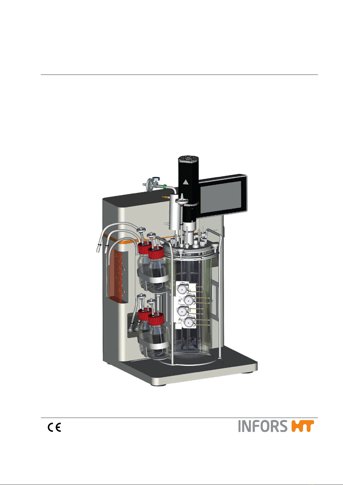
Minifors 2
Benchtop Bioreactor
Dok-ID: 75623 / V.03.00 - Original

Infors AG
Headoffice, Schweiz
Rittergasse 27
CH-4103 Bottmingen
T +41 (0)61 425 77 00
F +41 (0)61 425 77 01
info@infors-ht.com
service@infors-ht.com
Infors GmbH
Dachauer Str. 6
D-85254 Einsbach
T +49 (0)8135 8333
F +49 (0)8135 8320
infors.de@infors-ht.com
Infors UK Ltd
The Courtyard Business Centre
Dovers Farm, Lonesome Lane,
Reigate
Surrey, RH2 7QT, UK
T +44 (0)1737 22 31 00
F +44 (0)1737 24 72 13
infors.uk@infors-ht.com
Infors Sarl
2, rue du Buisson aux Fraises
Bâtiment D13
F-91300 Massy
T +33 (0)1 69 30 95 04
F +33 (0)1 69 30 95 05
infors.fr@infors-ht.com
www.infors-ht.fr
Infors Benelux BV
Markweg 9-A, NL-6883 JL
Velp (GLD)
P.O. Box 125, NL-6880 AC
Velp (GLD)
T +31 (0)26 369 31 00
F +31 (0)26 369 31 09
infors.bnl@infors-ht.com
Infors USA Inc.
9070 Junction Drive, Suite D
Annapolis Junction, MD20701
T +1 301 362 3710 /
T +1 855 520 7277 (toll-free USA)
F +1 301 362 3570
infors.usa@infors-ht.com
www.infors-ht.us
Infors Canada
8350 rue Bombardier
Anjou, Quebec
Canada H1J 1A6
T +1 514 352 5095
F +1 514 352 5610
infors.ca@infors-ht.com
Infors Bio-Technology
(Beijing) Co., Ltd.
Room 505C, Building 106
Lize Zhongyuan
Wangjing New Industrial Zone
Chaoyang District, Beijing
100102 P.R. of China
T +86 10 51652068
F +86 10 64390585
info@infors-ht.com.cn
Infors South East Asia
16, 1st Floor, Taman City
MY-51200 Kuala Lumpur
Malaysia
T +603 625 771 81
F +603 625 067 48
info@infors-ht.com.my
Infors LATAM Ltda.
Rua Dr. Alceu de Campos
Conjunto 205
CEP: 04544-000
São Paulo – SP
Brasil
T +55 (11) 95304-0201
F +55 (11) 98585-5334
Infors.br@infors-ht.com
Contact details of our local dealers worldwide can be found
on our website.
www.infors-ht.com
Engineering and production in Switzerland

Minifors 2 - Benchtop Bioreactor
Table of Contents
07 February 2019 Page 1of 214
1General Information ...............................................................9
1.1 About this Manual ..........................................................9
1.2 Explanation of Special Notices ......................................9
1.2.1 Warning Notices .............................................9
1.2.2 Other Notices................................................10
1.3 Equipment Identification (Standard Identification Plate)
.....................................................................................10
1.4 Declaration of Conformity ............................................11
1.5 Customer Service and Services ..................................11
2Safety and Responsibility ...................................................12
2.1 Intended Use, Incorrect Use and Misuse ....................12
2.2 Qualified Personnel .....................................................13
2.2.1 Provider ........................................................13
2.2.2 User ..............................................................13
2.2.3 Operator .......................................................14
2.3 Unauthorised Persons .................................................15
2.4 Responsibility of the Provider ......................................15
2.5 General Hazards..........................................................15
2.5.1 Electrical Current..........................................16
2.5.2Unauthorised Spare Parts and Accessories 16
2.6 Particular Hazards .......................................................16
2.6.1 Hot Surfaces.................................................17
2.6.2 Dangerous Gases ........................................17
2.6.3 Flammable or Explosive Substances ...........17
2.6.4 Corrosive or Toxic Substances ....................17
2.6.5 Bioactive Substances or Pathogenic
Organisms ....................................................18
2.6.6 Overpressure or Vacuum .............................18
2.7 Warning Symbols on the Equipment ...........................18
2.8 Declaration of Decontamination...................................19
3Setup and Function..............................................................20
3.1 Basic Unit.....................................................................20
3.1.1 Main Switch ..................................................21
3.1.2 LED Strip ......................................................21
3.1.3 Pumps ..........................................................21
3.1.4 Identification Plate ........................................22
3.1.5 Power Connection ........................................23
3.1.6 Water Connections .......................................23
3.1.7 Gas Connections ..........................................23
3.1.8 Signal Connections ......................................24
3.1.9Motor Cable Connection...............................24

Minifors 2 - Benchtop Bioreactor
Table of Contents
Page 2of 214 07 February 2019
3.1.10 Connections for Sensors (Sensor Cables) ...25
3.1.11 Sparger Connection (Gassing) .....................25
3.1.12 Connections and Water Flow Control Valve
for the Exit Gas Cooler .................................26
3.2 Operating Panel ...........................................................27
3.3 Culture Vessel..............................................................27
3.3.1 Top Plate ......................................................29
3.3.2 Ports in the Vessel Top Plate and their
Configuration ................................................30
3.3.3 Vessel Top Plate, Nominal Width 90............30
3.3.4 Vessel Top Plate, Nominal Width 115..........31
3.3.5 Vessel Top Plate, Nominal Width 145..........32
3.4 Temperature Control System.......................................33
3.5 Stirrer ...........................................................................34
3.6 Gassing System ...........................................................35
3.6.1 Gas Entry......................................................36
3.6.2 Exit Gas ........................................................36
3.7 pH Control ....................................................................36
3.7.1 Measurement System...................................36
3.8 pO2Control...................................................................37
3.8.1 Measurement System...................................38
3.9 Antifoam Control ..........................................................39
3.9.1 Antifoam Sensor ...........................................39
4Options..................................................................................40
4.1 Turbidity Measurement ................................................40
4.1.1 Sensors.........................................................41
4.1.2 Calibrating the Zero Point .............................41
4.1.3 Mounting the Sensor ....................................42
4.1.4 Cleaning and Storing the Sensor..................42
4.1.5 Interferences Turbidity Measurement...........43
4.1.6 Specifications................................................43
4.2 Exit Gas Analysis .........................................................44
4.2.1 Gas Sensors .................................................44
4.2.2 Connecting the Gas Sensor .........................44
4.2.3 Calibrating the Gas Sensor ..........................45
5Accessories ..........................................................................46
5.1 Cone Plug for Drive Hub ..............................................46
5.2 Sparger ........................................................................47
5.3 Baffles ..........................................................................47
5.4 Blanking Plugs .............................................................48
5.5 Clamping Adapters and Fastening Screws..................48

Minifors 2 - Benchtop Bioreactor
Table of Contents
07 February 2019 Page 3of 214
5.6 Electrode Holder ..........................................................49
5.7 Addition Port Adapters and Feed Needles ..................50
5.8 Septum Collar ..............................................................51
5.9 Dip Tubes.....................................................................51
5.10 Pocket for Temperature Sensor (Pt100)......................52
5.11 Exit Gas Cooler............................................................53
5.12 Reagent Bottles ...........................................................54
5.13 Sampling System Super Safe Sampler .......................54
5.14 Pump Heads ................................................................57
5.15 Vessel Holder with Built-in Holder for Reagent Bottles
and Pumps...................................................................58
5.16 Sterile Filters ................................................................58
5.17 Hoses and Accessories ...............................................60
5.18 O-Rings and Gaskets ..................................................61
5.19 Inoculation Accessories and Tools ..............................61
5.20 Starter Kit .....................................................................62
5.21 Service Sets.................................................................62
5.22 Auxiliary Supplies ........................................................62
6Transport and Storage ........................................................63
6.1 Transport......................................................................63
6.2 Storage ........................................................................64
7Installation and Initial Operation ........................................65
7.1 General Location Requirements for Installation ..........65
7.2 Minimum Distances .....................................................65
7.3 Connecting the Equipment to On-Site Supply Lines ...65
7.3.1 Power Supply ...............................................66
7.3.2 Water Supply and Return .............................66
7.3.3 Gas Supply...................................................67
7.3.4 Exit Gas ........................................................68
7.4 Connecting the Motor Cable ........................................68
7.5 Test Run ......................................................................69
7.5.1 Preparation Test Run ...................................69
7.5.2 Cooling System ............................................70
7.5.3 Stirring ..........................................................71
7.5.4 Heating and Adjusting Temperature ............71
7.5.5 Gassing ........................................................72
7.5.6 End of Test ...................................................72
8Before Cultivation ................................................................74
8.1 Preparing and Autoclaving the Culture Vessel ............74
8.1.1 Checking Gaskets (O-Rings)........................74
8.1.2 Mounting the Impellers .................................75

Minifors 2 - Benchtop Bioreactor
Table of Contents
Page 4of 214 07 February 2019
8.1.3 Mounting Dip Tubes and Spargers...............76
8.1.4 Inserting the Vessel into the Vessel Holder..77
8.1.5 Inserting the Baffles ......................................78
8.1.6 Moistening/Filling the Culture Vessel ...........79
8.1.7 Fitting the Vessel Top Plate..........................79
8.1.8 Mounting the Blanking Plugs ........................80
8.1.9 Mounting Addition Port Adapters..................81
8.1.10 Mounting the Feed Needle(s) .......................82
8.1.11 Mounting the Pocket for Temperature Sensor
(Pt100) ..........................................................82
8.1.12 Equipping the Port with a Septum Collar and
Septum for Inoculation..................................82
8.1.13 Preparing the Dip Tube/Addition Port Adapter
for Inoculation ...............................................83
8.1.14 Mounting the Exit Gas Cooler.......................84
8.1.15 Preparing the Sensors..................................85
8.1.16 Calibrating the pH Sensor ............................86
8.1.17 Mounting a Sensor into a 12 mm Port..........86
8.1.18 Mounting Sensors with Electrode Holder .....87
8.1.19 Mounting the Antifoam Sensor .....................89
8.1.20 Preparing the Super Safe Sampler...............91
8.1.21 Mounting the Sparger Hose and the Inlet Air
Filter ..............................................................92
8.1.22 Preparing the Reagent Bottles, Pumps and
Hoses............................................................93
8.1.23 Sterile Hose Connections .............................96
8.1.24 Setting the Pumps ........................................97
8.1.25 Removing the Pump Heads..........................97
8.1.26 Fitting the Cone Plug for Drive Hub..............98
8.1.27 Checklist Before Autoclaving........................98
8.1.28 Autoclaving ...................................................99
8.2 Connecting the Culture Vessel and Preparing the
Cultivation ..................................................................101
8.2.1 Hang the Culture Vessel in Place and Fit the
Pump Heads ...............................................101
8.2.2 Filling the Reagent Hoses ..........................101
8.2.3 Connecting the Gassing .............................102
8.2.4 Connecting the Exit Gas Cooler .................102
8.2.5 Coupling the Motor .....................................103
8.2.6 Filling the Culture Vessel............................104
8.2.7 Connecting the Temperature Sensor (Pt100)
....................................................................105
8.2.8 Connecting the Antifoam Sensor................105
8.2.9 Connecting the pH Sensor .........................106

Minifors 2 - Benchtop Bioreactor
Table of Contents
07 February 2019 Page 5of 214
8.2.10 Connecting the pO2Sensor........................106
8.2.11 Calibrating the pO2Sensor.........................107
8.2.12 Checking the Hoses and Hose Connections
....................................................................107
9Cultivation...........................................................................108
9.1 Preparing the Medium ...............................................108
9.2Sampling ....................................................................109
9.3 Inoculation..................................................................112
9.3.1 Inoculation with a Syringe ..........................113
9.3.2 Inoculation Using Dip Tube / Addition Port
Adapter .......................................................113
9.4 Harvest.......................................................................114
9.5 Emptying the Culture Vessel .....................................115
9.6 Emptying the Reagent Hoses ....................................115
9.7 Switching off the Equipment ......................................115
9.8 Autoclaving the Culture Vessel After Cultivation .......116
10 Operation ............................................................................118
10.1 Screen Areas, Menu Navigation and Control Elements
...................................................................................118
10.1.1 Main Screen ...............................................120
10.1.2 EDIT VIEW .................................................121
10.1.3 START BATCH / INOCULATE / STOP
BATCH .......................................................122
10.1.4 SAMPLE NOW ...........................................123
10.2 Menus for System Settings........................................124
10.2.1 VESSEL TYPE – Selecting a Culture Vessel
....................................................................125
10.2.2 APPEARANCE – Display Settings .............126
10.2.3 NETWORK SETTINGS ..............................128
10.2.4 eve COMMUNICATION – Communication
Settings.......................................................130
10.2.5 USB Data Export and Import from a USB
Stick............................................................131
10.2.6 SYSTEM INFO – System Information........134
10.3 Parameter - Parameter Groups .................................134
10.3.1 Parameters – Displays and Functions .......135
10.3.2 SETPOINT - Setting the Setpoint...............137
10.3.3 Parameter Alarms ......................................138
10.3.4 Cascades....................................................140
10.4 MAIN Parameter Group .............................................141
10.4.1 Temperature...............................................141
10.4.2 Stirrer..........................................................141
10.4.3 pH ...............................................................141

Minifors 2 - Benchtop Bioreactor
Table of Contents
Page 6of 214 07 February 2019
10.4.4 pO2..............................................................143
10.4.5 TotalFlow ....................................................146
10.4.6 GasMix........................................................146
10.4.7 Foam...........................................................147
10.5 EXTENDED Parameter Group...................................149
10.5.1 Turbidity (Optional) .....................................149
10.5.2 Balance (Optional) ......................................149
10.5.3 AirFlow........................................................149
10.5.4 Gas2Flow....................................................150
10.6 EXITGAS Parameter Group.......................................151
10.6.1 Exit Gas O2.................................................151
10.6.2 Exit Gas CO2..............................................152
10.7 PUMPS Parameter Group - General Information ......152
10.7.1 Configuring the Pumps ...............................154
10.7.2 Pump1 - Acid or Additional Feed Solution..155
10.7.3 Pump2 - Base or Additional Feed Solution 156
10.7.4 Pump3 - Antifoam, Level or Additional Feed
Solution.......................................................156
10.7.5 Pump4 - Feed Solution...............................157
10.7.6 AUTO FILL/EMPTY – Automatically
Filling/Emptying Pump Hoses.....................158
10.8 Calibration ..................................................................159
10.8.1 Calibrating the pH Sensor - General
Information..................................................159
10.8.2 Calibrating the pH Sensor - Procedure ......160
10.8.3 pH Sensor Product Calibration ...................165
10.8.4 Calibrating the pO2Sensor - General
Information..................................................168
10.8.5 Calibrating the pO2 sensor - Procedure ......169
10.8.6 Calibrating the Turbidity Sensor - General
Information..................................................176
10.8.7 Calibrating the Turbidity Sensor - Procedure
....................................................................176
10.9 PID Controller – Basic Principle.................................178
10.9.1 Table with Setting Values for PID Controller
....................................................................180
10.9.2 Useful Information for Changing PID
Controller Settings ......................................180
10.9.3 Adjusting PID Settings................................181
10.10 Alarms – Equipment Alarm Menu ..............................181
11 Cleaning and Maintenance................................................183
11.1 Cleaning Agent and Disinfectant................................183
11.2 Cleaning the Culture Vessel - Routine Cleaning .......183
11.3 Removing the Vessel Top Plate and Accessories .....185

Minifors 2 - Benchtop Bioreactor
Table of Contents
07 February 2019 Page 7of 214
11.3.1 Removing the Exit Gas Cooler ...................185
11.3.2 Removing the Sensors ...............................185
11.3.3 Removing Hoses, Filters and Pump Heads
....................................................................186
11.3.4 Removing Blanking Plugs ..........................187
11.3.5 Removing the Septum Collar and Septum.187
11.3.6 Removing Addition Port Adapters, Feed
Needle and Temperature Sensor Pocket...187
11.3.7 Removing the Vessel Top Plate .................187
11.3.8 Removing the Sparger and the Dip Tube(s)
....................................................................188
11.3.9 Removing the Impellers..............................189
11.4 Cleaning and Storing Individual Parts .......................189
11.5 Cleaning the Sensors ................................................190
11.6 Cleaning the Hoses and Pump Heads ......................190
11.7 Cleaning the Super Safe Sampler .............................191
11.8 Cleaning the Exit Gas Cooler ....................................191
11.9 Cleaning the Basic Unit and Operating Panel ...........192
11.10 Maintenance Plan ......................................................192
11.11 Decalcifying the Equipment .......................................193
12 Interferences.......................................................................195
12.1 Interferences Basic Unit and Operating Panel ..........195
12.2 Interferences Drive System .......................................196
12.3 Interferences Temperature Control System ..............197
12.4 Interferences Gassing System...................................197
12.5 Interferences pH-System ...........................................198
12.6 Interferences pO2 System ..........................................200
12.7 Interferences Antifoam/Level Sensor and Antifoam
Pumps........................................................................201
12.8 Interferences Addition of Feed Solution (Feed Pump)
...................................................................................202
12.9 Returning for Repair ..................................................202
13 Disassembly and Disposal................................................203
13.1 Disassembly...............................................................203
13.2 Disposal .....................................................................203
14 Technical Data....................................................................205
14.1 Equipment Dimensions..............................................205
14.2 Dimensions of Culture Vessel....................................206
14.3 Weights (netto)...........................................................207
14.4 Connection Requirements .........................................207
14.4.1 Electrical .....................................................207
14.4.2 Water IN, Basic Unit ...................................207

Minifors 2 - Benchtop Bioreactor
Table of Contents
Page 8of 214 07 February 2019
14.4.3 Water OUT, Basic Unit ...............................207
14.4.4 Gas (Air, O2or N2) ......................................208
14.5 Specifications .............................................................208
14.5.1 Operating Panel..........................................208
14.5.2 Culture Vessels...........................................208
14.5.3 Stirrer ..........................................................209
14.5.4 Temperature ...............................................210
14.5.5 Gassing.......................................................211
14.5.6 pH ...............................................................211
14.5.7 pO2..............................................................212
14.5.8 Antifoam......................................................212
14.5.9 Pumps.........................................................213
14.6 Operating Conditions .................................................213
14.7 Emissions...................................................................213
14.8 Auxiliary Supplies.......................................................214

Minifors 2 - Benchtop Bioreactor
General Information
07 February 2019 Page 9of 214
1 General Information
1.1 About this Manual
This manual enables the safe and efficient handling of the equip-
ment.
All the information and instructions in this operating manual comply
with the current standards, legal regulations, the latest technologi-
cal and scientific developments and the knowledge gained from the
manufacturer’s many years of experience in this field.
This operating manual is a component part of the equipment.
It must be kept near to the equipment and must be accessible
to the operators at all times.
The users must read the operating manual thoroughly and fully un-
derstand its contents before beginning any work.
Adhering to all the safety and operating instructions in this manual
is essential to ensure that work is carried out safely.
The scope of delivery may differ from the explanations, descrip-
tions and figures in this operating manual due to special designs,
additional options specified on ordering and the latest tech-
nical/mechanical modifications.
This manual contains illustrations to aid general understanding.
These may differ from the actual equipment as supplied.
1.2 Explanation of Special Notices
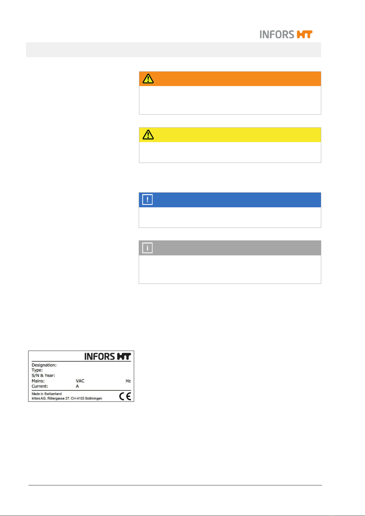
1.2.1 Warning Notices
Warning notices in this manual are indicated by a coloured bar and
begin with a signal word that signifies the degree of the hazard.
DANGER
The signal word “DANGER” indicates a dangerous situation that
will lead to severe or even fatal injuries if not avoided.
Minifors 2 - Benchtop Bioreactor
General Information
Page 10 of 214 07 February 2019
WARNING
The signal word “WARNING” indicates a potentially dangerous
situation that may result in severe or even fatal injuries if not
avoided.
CAUTION
The signal word “CAUTION” indicates a potentially dangerous
situation that may result in minor injuries if not avoided.
1.2.2 Other Notices
ATTENTION
The word “ATTENTION” on a blue bar indicates a situation that
may result in significant damage to property if not avoided.
INFORMATION
Texts located below a grey bar bearing the notice “INFOR-
MATION” provide useful tips and recommendations for ensuring
efficient, fault-free operation of the equipment.
1.3 Equipment Identification (Standard Identification Plate)
The identification plate is designed to allow clear identification of
the equipment. It contains the following information:
Manufacturer name
Designation = Category of equipment
Type = Equipment type (name)
S/N = Serial number
Year = Year of manufacture
Mains = Nominal voltage and frequency
Current = Current consumption
Manufacturer address
CE marking

Minifors 2 - Benchtop Bioreactor
General Information
07 February 2019 Page 11 of 214
1.4 Declaration of Conformity
The equipment is in compliance with the essential requirements of
the following Directives:
Machinery Directive 2006/42/EC
EMC Directive 2014/30/EU
The Declaration of Conformity according to EC Machinery Directive
2006/42/EC, annex II 1 A is included in the general documentation
supplied with the equipment.
1.5 Customer Service and Services
Our Customer Service is at your disposal for technical advice and
specialist enquiries. For contact information, see page 2.
Due to their familiarity with the potential applications of the equip-
ment, the Customer Service team is able to provide information on
whether the equipment can be used for a specific application or
modified to handle the planned process.
Experience of working with the equipment will be published semi-
regularly on the manufacturer’s website in the form of “application
notes”.
Furthermore, our colleagues are always interested in new infor-
mation and experiences resulting from user’s applications for the
equipment that may be valuable for the continued development of
our products.

Minifors 2 - Benchtop Bioreactor
Safety and Responsibility
Page 12 of 214 07 February 2019
2 Safety and Responsibility
This section describes general considerations relating to user
safety that must be taken into account when working with the
equipment.
In the remaining sections, warning notices are used only to high-
light particular hazards directly arising from the actions being de-
scribed in the section in question.
It is essential to read the operating manual carefully – espe-
cially this section and the warning notices in the text – and to
follow the instructions therein.
This section also refers to areas that are the responsibility of the
provider due to certain risks arising from particular applications for
which the equipment is used deliberately and with full awareness
of the associated risks.
2.1 Intended Use, Incorrect Use and Misuse
The bench-top bioreactor Minifors 2 from INFORS HT is de-
signed especially for research and development and for the
cultivation of microorganisms in a biotechnology laboratory.
The equipment is designed and constructed exclusively for the in-
tended use described above.
Intended use also includes following all the instructions in this op-
erating manual, especially those relating to:
The installation site
User qualifications
Correct operation and maintenance
The use of undamaged tubing and glass vessels
Any failure to observe the requirements specified in this manual
shall be deemed incorrect use.
Any use of the equipment outside the scope of the intended use as
described above shall be deemed misuse.
This also applies to applications for which the equipment is not de-
signed, such as the use or production of explosive gases, which is
not permitted because the equipment is not explosion-proof.

Minifors 2 - Benchtop Bioreactor
Safety and Responsibility
07 February 2019 Page 13 of 214
For use for special applications not covered by conventional, in-
tended use, the equipment must be modified and certified accord-
ingly by the manufacturer.
Any use of the equipment outside of a biotechnology laboratory,
i.e. in any environment in which the conditions required for the
safety of the users cannot be fulfilled or cannot be fulfilled to their
full extent, shall also be deemed misuse.
2.2 Qualified Personnel
Due to the complexity of the equipment and the potential risks aris-
ing from its operation, the equipment may only be used by quali-
fied, specialist personnel.
2.2.1 Provider
The term “provider” applies to all persons who are responsible for
making the equipment and the necessary infrastructure available.
These persons may also be included in the group of people known
as “users”, though this is not always the case.
Irrespective of whether a provider is a member of the company’s
board of management or a supervisor, they bear a special level of
responsibility with regard to the processes and the qualification and
safety of the users.
2.2.2 User
General
The term “user” applies to all persons who come into contact with
the equipment in any way and perform work on or with it. This pri-
marily applies to the following activities, which can be performed by
the manufacturer’s own specialists or a variety of other persons (it
is not always possible to distinguish clearly between the different
types of person):
Assembly, installation and commissioning
Definition and preparation of the process
Operation
Troubleshooting and remedying of faults
Maintenance and cleaning (autoclaving, if necessary)
Service work and repairs
Disassembly, disposal and recycling

Minifors 2 - Benchtop Bioreactor
Safety and Responsibility
Page 14 of 214 07 February 2019
Qualified personnel
On account of their specific education, training and – in many
cases – experience, the qualified personnel required for this work
are able to recognise risks and respond accordingly to potential
hazards.
The qualified personnel (either internal or external) who cannot be
categorised under the separate “operators” group are made up of
the following groups of persons:
Electricians (electrical engineers)
Decontamination specialists
Repair specialists
Specialists in disassembly and (environmentally friendly) dis-
posal
Recycling specialists
2.2.3 Operator
The “operators” are a specific sub-group of users distinguished by
the fact that they work with the equipment. They are the true target
audience for this operating manual.
Qualified technicians
Only technicians who have been trained for working in a biotech-
nology laboratory can be considered for the role of operator. These
include:
Process technicians in the fields of biotechnology and chemis-
try
Biotechnologists (biotechnicians)
Chemists with a specialisation in biochemistry; chemists in the
field of organic chemistry or biochemistry
Life scientists (biologists) with special education in cytology,
bacteriology, molecular biology, genetics, etc.
Lab assistants (lab technicians) from various fields
In order to be classed as a “sufficiently qualified technician” for the
operation of the equipment, the persons in question must have re-
ceived thorough training and have read and understood the operat-
ing manual.
The operator must be informed in a training session provided by
the provider of the tasks delegated to the operator and the poten-
tial risks of improper conduct. Tasks that go beyond the scope of
operation under normal conditions may only be performed by the
operator if this is specified in the manual and the provider has ex-
plicitly entrusted said tasks to the operator.

Minifors 2 - Benchtop Bioreactor
Safety and Responsibility
07 February 2019 Page 15 of 214
Technicians in training
Persons in this group who are undergoing training or apprentice-
ships are only permitted to use the equipment under supervision
and in accordance with the instructions of a trained and qualified
technician.
2.3 Unauthorised Persons
The term “unauthorised persons” applies to all persons who can
access the work area but are not qualified to use the equipment in
accordance with the aforementioned requirements.
Unauthorised persons are not permitted to operate the equipment
or use it in any other way.
2.4 Responsibility of the Provider
The equipment is used for industrial and scientific purposes. As
such, the provider of the equipment is individually liable with regard
to the legal requirements relating to occupational health and safety
in a biotechnology laboratory. In particular:
The provider is responsible for ensuring that the work and en-
vironmental regulations applicable in a biotechnology labora-
tory are observed.
The provider must ensure that the equipment remains in safe
and proper working condition throughout its entire term of use.
The provider must ensure that all safety equipment is fully
functional and is not disabled.
The provider must ensure that the equipment is only worked
on by qualified users, and that said users receive sufficient
training.
The provider must ensure that the protective equipment re-
quired for working with the equipment is provided and worn.
The provider must ensure that this operating manual remains
in the immediate vicinity of the equipment throughout its entire
term of use.
2.5 General Hazards
This section covers general hazards and residual risks that are al-
ways present when using the equipment in accordance with nor-
mal, intended use.

Minifors 2 - Benchtop Bioreactor
Safety and Responsibility
Page 16 of 214 07 February 2019
The following notices are general in nature. As such, with a few
exceptions they are not repeated in the remaining sections.
2.5.1 Electrical Current
The equipment runs on electrical power. There is an immediate
risk of fatal injury if contact is made with live parts.
The following points must be observed in order to avoid the risk of
fatal injury:
In case of damage to insulation, disconnect the equipment
from the mains immediately and arrange for it to be repaired.
Disconnect the equipment from the mains before commencing
any work on the electrical system.
Always use qualified electricians for any work on the electrical
system.
Keep moisture away from live parts. It may lead to a short cir-
cuit.
2.5.2 Unauthorised Spare Parts and Accessories
Incorrect or imitated spare parts and accessories as well as spare
parts or accessories that have not been authorised by the manu-
facturer represent a significant safety risk. As such, we recommend
procuring all spare parts and accessories from an authorised
dealer or directly from the manufacturer. For the contact details of
the manufacturer’s representatives, see page 2.
2.6 Particular Hazards
This section covers particular hazards and residual risks that may
arise when using the equipment for special applications in accord-
ance with normal, intended use.
Since the use of the equipment for such applications is deliberate,
it is the responsibility of the operators and the provider to ensure
that all personnel are protected from potential damage to health.
The provider is responsible for ensuring that the appropriate pro-
tective equipment for such applications is provided, and that the
necessary infrastructure is in place.

Minifors 2 - Benchtop Bioreactor
Safety and Responsibility
07 February 2019 Page 17 of 214
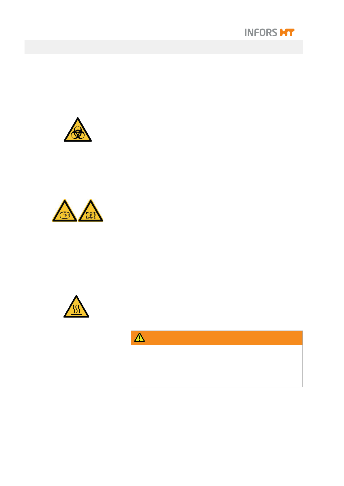
2.6.1 Hot Surfaces
For processes that are carried out with temperatures over 55 °C,
there is a danger of burns on hot surfaces.
Since the equipment is intended for applications at high tempera-
tures, it is the responsibility of the users to ensure that they have
sufficient protection.
The motor gets hot during operation. There is a risk of burns if it is
touched.
The thermal block and its adapter get hot during operation. There
is a risk of burns, if touched.
2.6.2 Dangerous Gases
The use or production of dangerous gases i.e. toxic or asphyxiant
gases entails a significant health risk, especially in enclosed
spaces.
In order to prevent high emissions of dangerous gases, the follow-
ing measures must be taken:
The gas connections on the equipment must be checked be-
fore any cultivation processes using dangerous gases are initi-
ated.
The gaskets on the equipment must be checked at regular
intervals and replaced if necessary.
Siphon off exit gas safely.
2.6.3 Flammable or Explosive Substances
The use or production of flammable or explosive substances is not
covered under “intended use” of the equipment, as the equipment
is not explosion-proof.
If the provider intends to use the equipment for such purposes, he
must check its suitability for the planned application with the re-
sponsible local authorities.
2.6.4 Corrosive or Toxic Substances
The use or production of corrosive or toxic substances entails a
significant health risk. As such, special measures must be taken to
protect the users for such applications.
Minifors 2 - Benchtop Bioreactor
Safety and Responsibility
Page 18 of 214 07 February 2019
Since the equipment is used deliberately for such applications, it is
the responsibility of the users to ensure that they have sufficient
protection.
2.6.5 Bioactive Substances or Pathogenic Organisms
The use or production of bioactive substances, pathogenic organ-
isms or genetically modified cultures entails a significant health
risk. As such, special measures must be taken to protect the users
for such applications.
Since the equipment is used deliberately for such applications, it is
the responsibility of the users to ensure that they have sufficient
protection.
2.6.6 Overpressure or Vacuum
Glass vessels may break or shatter when subjected to overpres-
sure or vacuums.
2.7 Warning Symbols on the Equipment
The following warning symbols (stickers) are attached to the equip-
ment:
Position
Thermal block adapter
Motor
WARNING
Illegible or missing warning symbols on the equipment will lead
to the user being exposed to risks that the warning symbols in
question were designed to make him or her aware of.
It is the provider’s responsibility to ensure that all the stickers
with warning symbols on the equipment are always intact.
Table of contents
Other Infors HT Laboratory Equipment manuals

Infors HT
Infors HT Labfors 5 User manual

Infors HT
Infors HT Ecotron User manual

Infors HT
Infors HT Labfors 5 Cell User manual

Infors HT
Infors HT Multifors 2 User manual

Infors HT
Infors HT Labfors 5 User manual

Infors HT
Infors HT Multitron Pro User manual

Infors HT
Infors HT Multitron User manual

Infors HT
Infors HT Multitron Standard User manual
Popular Laboratory Equipment manuals by other brands

Endress+Hauser
Endress+Hauser Analytik Jena TOPwave operating manual

Olympus
Olympus ENDO-AID Quick reference guide

REITEL
REITEL ERGORET CC operating instructions

Teledyne
Teledyne CombiFlash Companion XL installation guide

Quincy lab
Quincy lab GC Series operating manual

Metrohm
Metrohm 942 Extension Module Vario ONE/Deg manual


