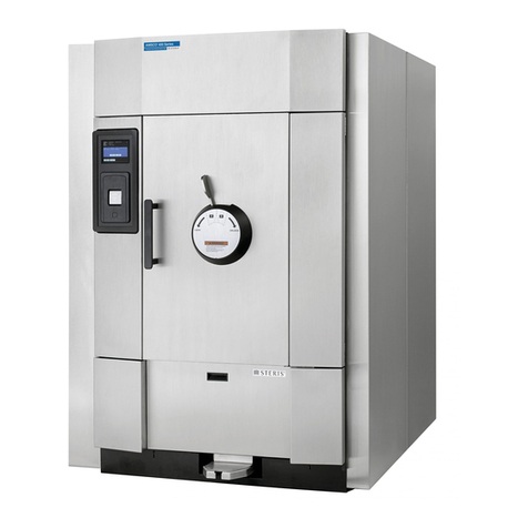
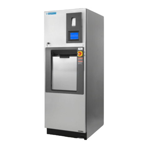
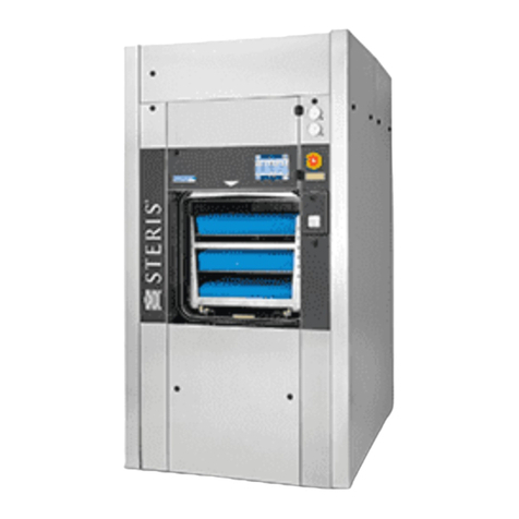
Amsco Century Series Instructions for use

Table of Contents RoutineMaintenance 129367-410
ROUTINE MAINTENANCE
Amsco®
Century®Series
Sterilizers
(05/27/05) P129367-410
Printed in U.S.A.
© 2005, STERIS Corporation, All rights reserved.

Table of Contents RoutineMaintenance 129367-410
A WORD FROM STERIS CORPORATION
This manual contains important information on proper maintenance of this
sterilizer.Alloperatorsanddepartmentheadsareurgedtocarefullyreviewand
becomefamiliarwiththewarnings,cautions,andinstructionscontainedherein.
This sterilizer is specifically designed to process goods using only the cycles
as specified in this manual. If there is any doubt about a specific material or
product, contact the manufacturer of the product for the recommended
sterilizationtechnique.
STERIS Corporation carries a complete line of accessories for this unit to
simplify, organize, and assure the sterilization process. Instrument trays,
pouches,andbiological/chemicalmonitoringsystems areallavailabletofulfill
your facility’s processing needs. A STERIS representative will gladly review
these with you.
A summary of the
Safety Precautions
to be observed when operating or
servicingthissterilizercanbe foundinSection1ofthis manual. Donotoperate
or service the sterilizer until you have become familiar with this information.
Thissterilizerisnotdesignedtoprocessflammablecompounds.Anyalteration
of the sterilizer which affects its operation will void the warranty, could
adversely affect sterilization efficacy, could violate federal, state and local
regulations,and jeopardize your insurancecoverage.
A thorough preventive maintenance program is essential to safe and proper
sterilizer operation. You are encouraged to contact STERIS concerning our
preventivemaintenanceagreement.Undertermsofthisagreement,preventive
maintenance, adjustments, and replacement of worn parts are done on a
scheduled basis to help assure optimal equipment performance and to help
avoid untimely or costly interruptions. STERIS maintains a nationwide staff of
well-equipped, factory-trained technicians to provide this service, as well as
expert repair services. Contact STERIS Corporation for details.
i
Advisory
Service
Information

Table of Contents RoutineMaintenance 129367-410
TABLE OF CONTENTS
iii
A WORD FROM STERIS CORPORATION ............................. i
1 LISTING OF SAFETY PRECAUTIONS ............................. 1-1
2 INSTALLATION VERIFICATION ..................................... 2-1
2.1 General ...................................................................................... 2-1
2.2 Installation Checklist .................................................................. 2-1
2.2.1 Service Clearance .............................................................. 2-1
2.2.2 Plumbing Service ............................................................... 2-1
2.2.3 Electrical Service ............................................................... 2-2
2.2.4 Sterilizer Final Check .........................................................2-2
2.2.5 Cycle Operation ................................................................. 2-2
3 PREVENTIVE MAINTENANCE ........................................ 3-1
3.1 PeriodicMaintenance Schedule ................................................. 3-1
3.2 Daily Maintenance ......................................................................3-4
3.2.1 Flush Optional Electric Steam Generator ........................... 3-4
3.2.2Clean Chamber Drain Strainer ............................................ 3-6
3.2.3CleanChamber .................................................................. 3-6
3.3 WeeklyMaintenance .................................................................. 3-7
3.4 AsRequired ............................................................................... 3-8
3.4.1 Change Printer Paper Roll .................................................. 3-8
3.4.2 Change Printer Ink Cartridge ............................................ 3-10
3.4.3 Replace Door Seal ........................................................... 3-12
4 SERVICE PROCEDURES ................................................. 4-1
4.1 Air Filter Replacement ................................................................ 4-1
4.2 Clean Strainers .......................................................................... 4-1
4.3 Steam Trap Replacement ........................................................... 4-3
4.4 Valves........................................................................................ 4-3
4.4.1 Clean or Replace Piping Check Valves ..............................4-3
4.4.2 Clean or Replace Manifold Check Valves ...........................4-3
4.4.3 Clean or Replace Manifold Solenoid Valves ....................... 4-3
4.4.4 Safety Valve Test .............................................................. 4-4
4.4.5 Pressure Regulating Valve Adjustment ..............................4-4
5 OPERATOR TROUBLESHOOTING .................................. 5-1
5.1 General ...................................................................................... 5-1
5.1.1 Typical Alarm Screen ......................................................... 5-1
5.1.2 Typical Alarm Printout ........................................................ 5-2
5.2 In-Cycle Alarms ......................................................................... 5-2
5.3 Out-of-Cycle Alarms ................................................................. 5-17
5.4 Sensor Alarms ......................................................................... 5-21
Section Title Page

1-1
Listing of Safety Precautions RoutineMaintenance 129367-410
LISTING OF SAFETY PRECAUTIONS 11
Thefollowinglistof
SafetyPrecautions
must be observedwhenoperatingor servicingthisunit.WARNINGS indicate
thepotentialfordangertopersonnel,andCAUTIONSindicatethepotentialfordamagetoequipment.Theprecautions
are repeated (in whole or in part) where applicable throughout the manual. Carefully read these
Safety Precautions
before proceeding to use or service the unit.
WARNING — BURN HAZARD:
Beforeperforminganycleaningormaintenanceprocedures,allowsterilizer,generator(ifapplicable) and
accessories to cool to room temperature.
Sterilizerand rack/shelveswill beHOTafter cycleis run. Alwayswearprotectiveglovesand apron (also face
shield if processing liquids) when removing a processed load. Protective gloves and apron should also be worn
whenreloading sterilizer followingprevious operation.
Asteamsupplymalfunction,identifiedbyanaudible(warbletone)andvisualalarm,cancausethesterilizer
chamber to fill with scalding water.
• Do not open the door.
• Call for service immediately.
Before daily flushing of the generator, generator must be at 0.0 psig and cooled to room temperature.
Failure to shut off the steam supply when cleaning or replacing strainers can result in serious injury.
Jacket pressure must be at 0.0 psig before beginning work on the steam trap.
Proper testing of the safety valve requires the valve to be under pressure. Exhaust from the safety valve
is hot and can cause burns. Proper safety attire (gloves, eye protection, insulated overalls) as designated by
OSHA are required. Testing is to be performed by qualified service personnel only.
Sterilizer operatormay be severelyburned by scaldingwater if thewaterlevel controlmalfunctions. The
steam generator level control may malfunction if the supply water exceeds 26,000 ohms/cm (38.5 micromhos
conductivityminimum).Do not connect totreatedwater (e.g., distilled, reverseosmosis,deionized) unless water
resistivity is determined to be acceptable. If water exceeds 26,000 ohms/cm, contact STERIS for information
concerning modifications required to the generator control system.
WARNING — ELECTRIC SHOCK HAZARD:
Disconnectallutilities to sterilizerbeforeservicing. Do not service thesterilizerunless all utilitieshavebeen
properlylockedout. Always follow OSHALockout-Tagoutand electrical safety-related workpractice standards.
(See 29 CFR 1910.147 and .331 through .335.)
Disconnectfacilitypowerorplacecontroldisconnectswitch,locatedoncontrolbox,toOFFbeforeremoving
or replacing any fuses or printed circuits boards from the sterilizer's control section.
WARNING — EXPLOSION HAZARD:
This sterilizer is not designed to process flammable compounds.
WARNING — SLIPPING HAZARD:
Toavoidslipperyfloor conditions, immediatelywipeup any spilled liquidsorcondensationin sterilizer loading
orunloadingarea(s).
1-2
129367-410 RoutineMaintenance Listing of Safety Precautions
WARNING — STERILITY ASSURANCE HAZARD:
Load sterility may be compromised if the biological air removal or air leak test indicates a potential
problem. If these indicators show a potential problem, refer the situation to a qualified service technician before
using the sterilizer further.
According to AAMI standards, a measured leak rate greater than 1.0 mm Hg/minute indicates a problem
with the sterilizer. Refer the situation to a qualified service technician before using the sterilizer further.
WARNING—PERSONALINJURYAND/OREQUIPMENTDAMAGE HAZARD:
Safe and reliable operation of this equipment requires regularly scheduled preventive maintenance in
addition to the faithful performance of routine maintenance. Contact STERIS to schedule preventive mainte-
nance.
Repairsandadjustmentstothisequipmentmustbemadeonlybyfullyqualifiedservicepersonnel.Maintenance
performed by inexperienced, unqualified persons or the installation of unauthorized parts could cause personal
injury or result in costly equipment damage.
WARNING — PERSONAL INJURY HAZARD:
Keep hands and arms out of the door opening when closing the door.
CAUTION — POSSIBLE EQUIPMENT DAMAGE:
Insufficient service clearance will make repairs more difficult and time consuming.
Piping sized too small may cause water hammer, resulting in damage to the sterilizer.
Never use a wire brush, abrasives or steel wool on door and chamber assembly. Do not use cleaners containing
chloride on stainless-steel surfaces. Chloride based cleaners will deteriorate stainless-steel eventually leading
to failure of the vessel.
After installation, it is mandatory to brace piping at the drain funnel so that it will not move vertically.
Allow thermostatic traps to cool to room temperature before removing cover. Since there is nothing to limit
expansion, the bellows may rupture or fatigue if trap is opened while hot.
Actuationat less than 75%of rated pressurecan allow debris tocontaminate the seatand cause the safetyvalve
to leak. A leaking safety valve must be replaced.
Failure to flush generator on a daily basis could result in generator malfunctions. Warranty on the generator will
be voided unless flushed daily.
Before flushing generator, ensure generator drain valve is fully open to prevent generator heaters from turning
on during flush phase.
Sterilizationofchloride-containingsolutions(e.g., saline) can cause chamber corrosionandisnotrecommended
bythemanufacturer.If,however, chloride-containing solutions must be processed,cleanthechamberafter each
use.

2-1
Installation Verification RoutineMaintenance 129367-410
INSTALLATION VERIFICATION 2
An Equipment Drawing showing all utility and space requirements was
supplied with the sterilizer. Clearance space shown on the drawing is
necessary for ease of installation and to assure proper operation and mainte-
nance of equipment. Installation and Uncrating Instructions were also fur-
nished with the sterilizer. If any of these documents are missing or misplaced,
contact STERIS giving the Serial, Equipment and Model numbers. Replace-
ment copies will be sent to you promptly.
After installing this unit (see Fig. 2-1) according to the instructions provided,
completethefollowingchecklisttoassurethatyourinstallationiscompleteand
correct. Or, if you desire, contact STERIS for a technician to be scheduled to
test your installation and demonstrate proper equipment operation.
❑Clearance as specified on the Equipment Drawing must be available.
2.2 Installation
Checklist
CAUTION - POSSIBLE
EQUIPMENT DAMAGE:
Insufficientserviceclear-
ance will make repairs
moredifficultandtimecon-
suming.
2.2.1 Service
Clearance
❑FeedWater:
❑All supply line shutoffs must be provided with lockout capability.
❑Backflow prevention is by others.
❑Water Pressure measured (specification is 30 to 50 psig, static and
dynamic).
Waterpressuresupplied mustbewithinspecifications asshown
on the Equipment Drawing.If pressure is too high, a regulator must be
installed. If water pressure is too low, equipment performance will be
affected; use of a booster pump (by others) is recommended.
❑Water Quality supplied must be within specifications. Improper water
quality adversely affects equipment operation, especially units equipped
with an electric steam generator. Damage to the equipment from improper
water quality is not covered under warranty.
❑Steam Supply:
❑Shutoffs (with provisions for lockout and tag out) located nearby.
❑Supply piping adequately sized.
❑Supply pressure measured (specification is 50 to 80 psig, static and
dynamic).
❑Steam Piping to the sterilizer is to be trapped at a point before connection
to the sterilizer. Trap is required to remove condensate from the steam line.
❑Drain Piping must be sloped properly, and sized to handle the maximum
waste flow from the sterilizer.
2.2.2 Plumbing Service
CAUTION - POSSIBLE
EQUIPMENT DAMAGE:
Piping sized too small
maycausewaterhammer,
resultingindamagetothe
sterilizer.
CAUTION - POSSIBLE
EQUIPMENT DAMAGE:
Afterinstallation,itisman-
datory to brace piping at
the drain funnel so that it
will not move vertically.
2.1 General

2-2
129367-410 RoutineMaintenance Installation Verification
❑All disconnects must be provided with lockout capability.
❑120 VAC, one phase service to the unit must be as specified on the
EquipmentDrawing.
❑120VAC,onephase servicerequiresaclearly markeddisconnectlocated
near the sterilizer
❑120 VAC, one phase service should be on a separate circuit, and not tied
into circuits containing large reactive loads (e.g., motors).
❑Three phase power for optional electric steam generators must meet
specifications on the Equipment Drawing.
❑Threephaseservicerequiresaclearlymarkeddisconnect locatednearthe
sterilizer.
2.2.3 Electrical Service
❑Door runs up and down smoothly.
❑Door open/close time is 7.0-9.0 seconds (power door units).
❑Door up switches adjusted correctly.
❑Chamber strainer in place.
❑Rack and shelves/loading car operates correctly.
❑Paper loaded in printer.
❑Unit powers up correctly.
❑If prevacuum sterilizer, run leak test cycle — leak rate is to be less than
1.0 mmHg/minute.
❑Verify operation of a typical cycle (e.g., Gravity).
2.2.4 Sterilizer Final
Check
2.2.5 Cycle Operation
WARNING - EXPLOSION
HAZARD:Thissterilizeris
not designed to process
flammablecompounds.
CAUTION - POSSIBLE
EQUIPMENT DAMAGE:
Sterilization of chloride-
containingsolutions(e.g.,
saline) can cause cham-
ber corrosion and is not
recommended by the
manufacturer.If,however,
chloride-containingsolu-
tions must be processed,
clean the chamber after
eachuse.

2-3
Installation Verification RoutineMaintenance 129367-410
Foot
Pedal
Water
Supply
Valve
Steam
Supply
Valve
Main Power Disconnect
Century Sterilizer
GeneratorWater
Supply Valve
Sight
Glass
GeneratorDrainValve
Century
Control
Panel
CenturyControl
TouchScreen
Century Control
with Door Open
Printer
Optional Electric Steam
Generator
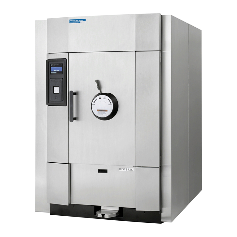
Figure 2-1. Typical Amsco® Century®Series Sterilizer

3-1
Preventive Maintenance RoutineMaintenance 129367-410
Table 3–1. Periodic Maintenance Schedule for Century Sterilizer
SERVICEREQUIRED BI-MONTHLYINSPECTION
123456
1.0 PREPARATIONS FOR PERIODIC MAINTENANCE
1.1 Discuss equipment operation with department personnel. X X X X X X
1.2 Inspect printouts for signs of trouble. X X X X X X
1.3 Install test equipment. X X X X X X
1.4 When necessary, shut off all building services (using lockout and tag
out procedures), and drain all utility lines. X X X X X X
2.0 DOOR ASSEMBLY
2.1 Verify door up proximity switch setting. X X X X X X
2.2 Check tension on power door cable. X X X X X X
2.3 Check door for smooth operation. X X X X X X
3.0 STEAM AND WATER SUPPLY HAND VALVE
3.1 Inspect each hand valve for smooth operation and proper valve seating. X X X X X X
3.2 Inspect valve for leaks. X X X X X X
Maintenanceprocedures describedin Sections 3and 4should be performed
regularly at the intervals indicated, using the maintenance schedule in
Table 3-1asa guide.Localconditions(waterquality, usage, etc.)mayrequire
more frequent maintenance than indicated. Refer to ILLUSTRATED PARTS
BREAKDOWN
publication(P129367-409) forreplacementpartslist.
If an operating problem occurs, refer to Section 5,
Troubleshooting
.
PREVENTIVE MAINTENANCE 3
WARNING - PERSONAL
INJURY AND/OR EQUIP-
MENTDAMAGEHAZARD:
Safe and reliable opera-
tion of this equipment re-
quires regularly sched-
uled preventive mainte-
nance in addition to the
faithful performance of
routinemaintenance.Con-
tact STERIS to schedule
preventivemaintenance.
3.1 Periodic
Maintenance
Schedule

3-2
129367-410 Routine Maintenance Preventive Maintenance
Table 3–1. Periodic Maintenance for Century Sterilizer (Cont'd)
SERVICEREQUIRED BI-MONTHLYINSPECTION
123456
4.0 MANIFOLDPIPING
4.1 Steam supply manifold — rebuild all components. X
4.2 Exhaust manifold — rebuild all components. X
4.3 Double door steam supply valve — rebuild all components. X
4.4 Double door exhaust manifold — rebuild all components. X
5.0 OTHERPIPING
5.1 Rebuild Pressure Regulating Valve. X
5.2 Rebuild jacket trap. X
5.3 Clean steam supply strainer. X
5.4 Clean water supply strainer. X
5.5 Test safety valve for proper operation. X
5.6 Check chamber and jacket pressure gauges for accuracy. X
5.7 Replace air inlet filter cartridge. X
5.8 Water Valves - rebuild valve(s). X
6.0 CONTROL
6.1 Check cooling fan operation. X X X X X X
6.2 Replace fan filter. X
6.3 Confirm control calibration. X
6.4 Replace battery. A/R
6.5 Verify operation of flood alarm control. X X X X X X
6.6 Replace printer. A/R
6.7 Replace ribbon cartidge.
7.0 ELECTRIC STEAM GENERATOR (IF APPLICABLE)
7.1 Discuss generator maintenance requiredwith department personnel. X
7.2 Flush generator (See
ATTENTION
note below this section). DAILY
7.3 Inspect all wiring and connections for damage and fraying. X X X X X X
7.4 Inspect control wiring. X X X X X X
7.5 Inspect fuses and fuse clips. X X X X X X
7.6 Inspect heater controls. X X X X X X
7.7 Inspect hand valves. X X X X X X
7.8 Replace hand valves. A/R

3-3
Preventive Maintenance RoutineMaintenance 129367-410
Table 3–1. Periodic Maintenance for Century Sterilizer (Cont'd)
SERVICEREQUIRED BI-MONTHLYINSPECTION
123456
7.0 ELECTRIC STEAM GENERATOR (IF APPLICABLE, Cont'd)
7.9 Replace check valves. X X X X X X
7.10 Inspect solenoid valves for proper operation (run a cycle). X X X X X X
7.11 Rebuild solenoid valves. X X
7.12 Verify operation of safety valve. X X
7.13 Clean strainers X X
7.14 Inspect gauge glass. DAILY
7.15 Replace water gauge glass and washers. X X
7.16 Inspect pressure control switches. X X X X X X
7.17 Verify proper setting of pressure switches (control safety and SP-1) X X X X X X
7.18 Verify pressure gauge. X X X X X X
7.19 Check proper operation of pressure gauge. X X X X X X
7.20 Clean water level control rods. X X X
7.21 Verify water level control operation. X X X X X X
7.22 Clean heating element and boiler chamber. X X X X X X
7.23Descalegenerator.* X X X
7.24 Determine water hardness, compare to specification. X X
7.25 Test safety valve for proper operation. X
ATTENTION: Warranty on this steam generator will be voided unless daily flushing procedures are performed. See
Daily Maintenance Instructions in this manual for proper instruction, or call STERIS for assistance.
*More frequent descaling may be necessary depending on local water quality and frequency of flush. Contact
STERIS for this service.
8.0 FINAL TEST
8.1 Clean lint and dirt from components. X X X X X X
8.2 Inspect wiring, terminals and socket connection for damage or fraying. X X X X X X
8.3 Run machine through each cycle to verify proper operation. Check
all displays and printouts. X X X X X X
8.4 Remove all test equipment installed for inspection. X X X X X X
8.5 Install any panel or cover removed during inspection. X X X X X X
8.6 Inspect areas to ensure removal of all materials used during inspection. X X X X X X

3-4
129367-410 Routine Maintenance Preventive Maintenance
If a building steam source is not available, the sterilizer may be equipped with
an electric steam generator. The generator automatically converts water to
steam using electric heat. The steam created is then used to power the
sterilizer.
Steam generators are highly susceptible to mineral scaling if the supplied
water has any level of hardness. Refer to Table 3-2 for water quality
requirements.
IMPORTANT: Regardless of the hardness level of supplied water, the
generator must be flushed every day before use to prevent mineral scaling or
carryover of debris into the chamber.
ATTENTION: Warranty on this steam generator will be voided unless daily
flushingprocedures are performed.
1. Press the ON button on the sterilizer touch screen (screen #0). Display
advancestoscreen#72.Instructionsonhowtoflushthegeneratorarelisted
on screen #72.
2. Check generator pressure gauge (see Fig. 3-1). Generator must be at
0.0 psig and room temperature before flushing.
72
FLUSHGENERATOR
STOP
TIMER
START
TIMER CANCEL
THE GENERATOR SHOULD BE FLUSHED
EVERY DAY.
TO FLUSH GENERATOR:
1 . VERIFY GENERATOR PRESSURE IS 0 psig.
2 . OPEN GENERATOR MANUAL DRAIN VALVE.
3 . PRESS START TIMER TO BEGIN
FLUSH PHASE.
4 . ALLOW GENERATOR TO FLUSH FOR
5 MINUTES.
FLUSH TIMER: 00:00
Pressing STOP TIMER stops flush
phase and resets timer to three
minutes.
Pressing CANCEL bypasses flush
phase and advances display to
screen #1. Do not press CANCEL
unless generator has already been
flushed that day.
Water-level
Sight Glass
Generator Drain Valve
Generator Pressure Gauge
Figure 3-1. Optional Steam Generator
Water Supply Valve to the
Generator
3.2 Daily
Maintenance
3.2.1 Flush Optional
Electric Steam
Generator
CAUTION - POSSIBLE
EQUIPMENT DAMAGE:
Failure to flush generator
on a daily basis could re-
sultingeneratormalfunc-
tions.Warrantyonthegen-
erator will be voided un-
less flushed daily.
WARNING - BURN HAZ-
ARD: Before daily flush-
ing of the generator,
generator must be at
0.0 psig and cooled to
roomtemperature.
CAUTION - POSSIBLE
EQUIPMENT DAMAGE:
Beforeflushinggenerator,
ensure generator drain
valve is fully open to pre-
vent generator heaters
from turning on during
flushphase.

3-5
Preventive Maintenance RoutineMaintenance 129367-410
*17.1 mg/L = 1 grain hardness
NOTE: If generator is not at 0.0 psig, the Flush can be bypassed by pressing
CANCEL, however the flush should not be bypassed on a continuous basis or
else damage to the generator will occur.
To ensure generator is at 0.0 psig the sterilizer can be shut off at end of the day
and by next morning the unit will be able to be flushed. Approximately seven
hours is required for generator to cool down to less than 140°F (60°C).
3. Open drain valve on the side of the generator electric box (see Fig. 3-1).
4. Verify that the water supply valve to the sterilizer are open.
5. Ensure the water supply valve to the generator is open (see Fig. 3-1).
6. Press START TIMER on screen #72. Water automatically flushes through
the generator and out the drain for five minutes. Flush timer on screen #72
counts down time remaining in the flush phase.
7. Afterfiveminutes,alarmbuzzersoundsanddisplayadvancestoscreen #73.
Instructions on how to restart the generator are listed on screen #73.
8. Close the generator drain valve.
9. PressCONTINUEonscreen#73.Generatorautomaticallyfillstotheproper
level and starts to heat. Display screen advances to the Main Menu
screen (#1). Allow 10 minutes warm-up time once generator starts to fill.
10. Close front cabinet panel.
NOTE: The generator must be flushed every day before use.
73
FLUSHING OF GENERATOR COMPLETE
TO RESTART GENERATOR:
1 . CLOSE GENERATOR MANUAL DRAIN VALVE.
2 . PRESS CONTINUE TO START THE
GENERATORANDADVANCE TO
THE MAIN MENU.
Table 3-2. Required Feed Water Quality for
Carbon Steel Steam Generators
Nominal Maximum
Condition Conditions Conditions
Temperature as supplied 140° F (60° C)
Total Hardness as CaCO3* 0-17 mg/L 130 mg/L
Total Dissolved Solids 50-150 mg/L 250 mg/L
Total Alkalinity as CaCO350-100 mg/L 180 mg/L
pH 6.8-7.5 6.5-8.5
Total Silica 0.1-1.0 mg/L 2.5 mg/L
Resistivity - ohms/cm 2000-6000 26000
WARNING-BURNHAZARD:
Sterilizer operator may be
severely burned by scald-
ing water if the water level
control malfunctions. The
steamgeneratorlevelcontrol
maymalfunctionifthesupply
water exceeds 26,000 ohms/
cm(38.5 Micromhos conduc-
tivitymin.).Donotconnectto
treated water (e.g., distilled,
reverse osmosis, deionized)
unlesswaterresistivity isde-
termined to be acceptable. If
waterexceeds26,000ohms/
cm, contact STERIS for in-
formationconcerningmodi-
ficationsrequiredtothegen-
eratorcontrolsystem.

3-6
129367-410 Routine Maintenance Preventive Maintenance
IMPORTANT: Thechamber drain strainermust be cleaned at leastonce a day,
preferably in the morning before running the first cycle.
1. Remove the drain strainer from the drain in the bottom of the chamber as
shown in Figure 3-2.
2. Removeany obviousdebrisfrom thestrainer.Ifnecessary, clearthescreen
in the strainer using a brush, wire or similar tool.
3. Onceithas beencleared ofobvious debris, reverseflush thestrainer under
runningwater.
4. Replace the strainer in the chamber drain.
Figure 3-2. Remove Chamber Drain Strainer
3.2.2 Clean Chamber
Drain Strainer
WARNING - BURN HAZ-
ARD: Before performing
any cleaning or mainte-
nance procedures, allow
sterilizer,generator(ifap-
plicable)andaccessories
to cool to room tempera-
ture.
IMPORTANT: The entire chamber should be wiped down and rinsed following
any spills or other soiling.
1. If applicable, the shelf assembly must be removed before cleaning the
chamber.
••
••
•Single Door
a. Use a 1-1/8-inch socket wrench to loosen and remove the rear
retaining nut (see Fig. 3-3) on the shelf assembly.
b. Use a 1/8-inch hex wrench to loosen (but don't remove) the six set
screws (see Fig. 3-3) at the front of the shelf assembly.
c. Carefullyslide the shelf assembly out fromthe operating (unloading)
end of the sterilizer.
••
••
•DoubleDoor
a. Loosen (but do not remove) the six set screws (see Fig. 3-3) at both
ends of the shelf assembly.
b. Carefully slide the shelf assembly out from the operating end of the
sterilizer.
3.2.3 Clean Chamber
WARNING - SLIPPING
HAZARD: To avoid slip-
pery floor conditions,
immediately wipe up any
spilledliquidsorconden-
sation in sterilizer load-
ing or unloading area(s).
WARNING - BURN HAZ-
ARD: Before performing
any cleaning or mainte-
nanceprocedures, allow
sterilizer,generator(ifap-
plicable)andaccessories
to cool to room tempera-
ture.

3-7
Preventive Maintenance RoutineMaintenance 129367-410
2.Wash the inside of the chamber and shelf assembly(plus any other loading
equipment) with a mild detergent solution such as STERIS Liqui-Jet 2*
InstrumentDetergent,Criti-Klenz®InstrumentDetergent,orcurrentSTERIS
equivalent.
IMPORTANT:Chamber must beat room temperature,sterilizeroff all night,
beforewashing.
3. Once the chamber is clean replace the shelf assembly reversing the
procedure given in Step 1.
*
Contact STERIS.
Flush chamber drain as follows whenever line becomes clogged:
a. Turn off steam supply valve. Wait until jacket pressure is zero. Wait
until chamber has cooled to room temperature.
b. Removechamberdrainstrainer(Fig.3-2).Clean strainerusingproce-
dures given above, if necessary.
c. Pour a solution of one pint of hot water and 1/4 cup of STERIS Liqui-
Jet 2* Instrument Detergent or Criti-Klenz®Instrument Detergent (or
current STERIS equivalent) into drain. Solution may puddle in the
bottom of the chamber.
d. Wait five minutes.
e. Close the door, turn the steam valve on and run a Gravity cycle set for
one minute sterilize and one minute dry.
f. Open door and place strainer back in drain.
Figure 3-3. Remove Chamber Shelf Assembly
CAUTION - POSSIBLE
EQUIPMENT DAMAGE:
Never use a wire brush,
abrasives or steel wool
on door and chamber as-
sembly.Donotuseclean-
erscontainingchlorideon
stainless-steel surfaces.
Chloride based cleaners
willdeterioratestainless-
steel eventurally leading
to failure of the vessel.
CAUTION - POSSIBLE
EQUIPMENT DAMAGE:
Sterilization of chloride-
containingsolutions(e.g.,
saline) can cause cham-
ber corrosion and is not
recommended by the
manufacturer.If,however,
chloride-containingsolu-
tionsmustbe processed,
clean the chamber after
eachuse.
3.3 Weekly
Maintenance
WARNING - BURN HAZ-
ARD: Before performing
any cleaning or mainte-
nance procedures, allow
sterilizer to cool to room
temperature.
Set
Screws
Retaining
Nut

3-8
129367-410 Routine Maintenance Preventive Maintenance
2. Remove take-up spool from drive by
inserting fingers in cavity as shown and
pushing spool to the right.
Finger
Cavity
3. Pull off right end of spool and remove
used paper roll from spindle.
4. Open access door and remove old paper roll, gently
pulling any remaining tape up and out of printer.
Access Door
1. Tear paper between take-up spool and
printer.
The printer paper roll should be changed whenever a colored stripe is visible
on one or both edges of the printout paper.
3.4 As Required
3.4.1 Change Printer
Paper Roll
Remove
Used Tape
Printer
(Behind Ink
Cartridge)

3-9
Preventive Maintenance RoutineMaintenance 129367-410
6. Insert end of paper into printer slot just
behind ink cartridge.
5. Insert new paper roll.
PAPER
FEED
MINI
STATUS
ABORT
7. Press PAPER FEED touch screen pad
on display until paper advances through
printer and ink cartridge, exiting the front.
8. Continue pressing PAPER FEED (or pull
tape
gently
) until about 18" (457 mm) of
paper hangs out of printer. Insert end of
paper into slot of take-up spool, then
replace right end of spool.
Pull Tape
Gently
Paper
Advances
Through
Printer

3-10
129367-410 Routine Maintenance Preventive Maintenance
9. Rotate spool in direction shown until paper
is secure.
Magnetic
Idler
10. Reinstall take-up spool on magnetic idler.
Manually roll up slack paper.
1. Tear paper between take-up spool and
printer. 2. Open access door, then press on right end
of ink cartridge, until left end of cartridge
pops out of the printer.
The printer ink cartridge should be changed as soon as the type on printouts
is light or faded, and before printouts become difficult to read.
3.4.2 Change Printer
Ink Cartridge

3-11
Preventive Maintenance RoutineMaintenance 129367-410
Ink
Ribbon
3. Slip cartridge off end of paper tape, slip new cartridge
over tape in the same way as before, making sure
paper tape slides between ink cartridge housing and
ink ribbon.
5. Retighten ribbon by rotating wheel on left
side of cartridge 1/4 turn. Then see
Section 3.4.1,
Change Printer Paper Roll,
Steps 8 through 10 to reinstall take-up
spool.
4. Install left end of cartridge first, then
push right end in as shown, snapping it
into place.
Rotate Wheel
1/4 turn to
tighten ribbon

3-12
129367-410 Routine Maintenance Preventive Maintenance
If the door seal requires replacement, perform the following:
1. Usea tonguedepressororsimilarnon-metaltoolto pryandtwistonesection
of the seal from the groove. Refer to Figure 3-4a.
2. Graspthe raisedsectionofthesealand pulltheremainderfromtheend-ring
groove.
3. Examine the end ring groove for debris or residue. Clean if necessary.
4. Install new seal as follows:
NOTE: When replacing the door seal, note the following:
1)Ensure date informationmolded intorear of seal(refer to Fig. 3-4b) isat the
bottom of the groove.
2) Reference indicators are located inside the rear groove of door seal, at the
middle of each side (refer to Fig. 3-4b).
•Do not use a sharp instrument to install the seal.
•Do not stretch the seal.
a. Align right and left reference indicators with the screws attaching the end
frame to the support stand, align top and bottom indicators with the ports
in the top and bottom of the end ring frame.
b. Press seal in at each reference point with fingertips.
c. Press remainder of the seal into end-ring groove, starting at the corners.
5. Test installation.
a. Attempttoclose the door. If the door jamsor sticks atany point in its travel
check to ensure the seal has been fully pressed into the groove.
b. Run a shortened test cycle to determine if the door seals adequately. If
steamleaksfromaroundthe doorortheseal, abort thecycleandexamine
thesealtoensureithasbeenproperlyseatedintheend-ringgroove.Once
re-seated, run another test cycle. If the door fails to seal following the
second test, another problem may exist. Contact your supervisor before
using the sterilizer further.
c. At the end of cycle, ensure seal has retracted fully into the groove.
3.4.3 Replace Door
Seal
WARNING - BURN HAZ-
ARD: Before performing
any cleaning or mainte-
nance procedures, allow
sterilizer,generator(ifap-
plicable)andaccessories
to cool to room tempera-
ture.
Table of contents
Other Amsco Laboratory Equipment manuals

Amsco
Amsco C Series User manual

Amsco
Amsco Century User manual

Amsco
Amsco EAGLE SERIES 3021 Installation and user guide

Amsco
Amsco HC-600 User manual

Amsco
Amsco 400 Series User manual

Amsco
Amsco RELIANCE 444 HTM User manual

Amsco
Amsco RELIANCE 300 User manual

Amsco
Amsco STERIS User manual

Amsco
Amsco 110LS User manual

Amsco
Amsco Evolution Series User manual
Popular Laboratory Equipment manuals by other brands

IKA
IKA C 3000 isoperibol operating instructions

Agilent Technologies
Agilent Technologies CrossLab RapidFire 400 quick start guide

Discus
Discus NV Microlaser user manual

Kinematica
Kinematica POLYTRON PT 2500 E operating instructions

Keysight
Keysight M9383A Security guide

Heidolph
Heidolph EKT 3001 instruction manual