LI-COR 6400-09 User manual

6400-09
Soil CO2Flux Chamber
Instruction Manual
Publication No. 9710-119
October, 1997
LI-COR, inc.
Environmental Division
4421 Superior Street
P.O. Box 4425
Lincoln, NE 68504 USA
Telephone: 402-467-3576
FAX: 402-467-2819
Toll-free 1-800-447-3576 (U.S. & Canada)
e-mail: [email protected]
URL: http://www.licor.com
© Copyright 1997, LI-COR, Lincoln, Nebraska USA

ii
NOTICE
The information contained in this document is subject to change without notice.
LI-COR MAKES NO WARRANTY OF ANY KIND WITH REGARD TO THIS
MATERIAL, INCLUDING, BUT NOT LIMITED TO THE IMPLIED
WARRANTIES OF MERCHANTABILITY AND FITNESS FOR A
PARTICULAR PURPOSE. LI-COR shall not be liable for errors contained herein
or for incidental or consequential damages in connection with the furnishing,
performance, or use of this material.
This document contains proprietary information that is protected by copyright. All
rights are reserved. No part of this document may be photocopied, reproduced, or
translated to another language without prior written consent of LI-COR, Inc.
© Copyright 1997, LI-COR Inc.

iii
Table of Contents
Section 1. General Information
Considerations .......................................................................................... 1-1
Precautions ........................................................................................ 1-5
Reference........................................................................................... 1-5
Section 2. Attaching the Soil Chamber
General Description .................................................................................. 2-1
Attaching the Sensor Head to the 6400-09............................................... 2-3
Section 3. Software
Configuring OPEN for Soil Measurements .............................................. 3-1
Creating a Soil Chamber Configuration ............................................ 3-1
Implementing the Soil Chamber Configuration ................................ 3-1
The Soil Chamber Configuration.............................................................. 3-2
OPEN's Main Screen ......................................................................... 3-2
Calib Menu ........................................................................................ 3-2
New Measurements Function Keys................................................... 3-2
User Variables ................................................................................... 3-4
Autoprograms .................................................................................... 3-6
Section 4. Making Measurements
Measuring With Soil Collars .................................................................... 4-2
Measuring Without Soil Collars ............................................................... 4-2
Making Measurements.............................................................................. 4-2
Position the Air Supply Manifold...................................................... 4-2
Check Hose Connections................................................................... 4-3
Measurement Procedure .................................................................... 4-4

iv
Section 5. Maintenance
Spare Parts Kit .......................................................................................... 5-1
Soil Temperature Probe ............................................................................ 5-1
Making Soil Collars .................................................................................. 5-2
Zeroing the IRGAs.................................................................................... 5-3
Zeroing the IRGA While Attached to the Soil CO2Flux Chamber .. 5-3
Setting the IRGA Span ...................................................................... 5-4
Section 6. Equation Derivation
Appendix A. Specifications
Warranty

General Information 1-1
1General
Information
Considerations
Soil carbon dioxide is primarily produced by root respiration, decay of
organic matter, and activity of microbes. Rainwater can have direct effects
as well, by displacing gas in soil pore spaces (enhancing CO2flux at the
surface), and by interacting with limestone soils. Also, rainwater itself
carries some dissolved CO2that can be released in the soil.
Thus, soil CO2flux is dependent on soil temperature, organic content,
moisture content and precipitation, and has a great deal of spatial
variability. Soil CO2flux is also extremely sensitive to pressure
fluctuations. An unvented chamber will induce significant pressure
increases just by pushing the chamber down over a sealed volume. Soil
water evaporation and heating of the air in the chamber head space also
induces pressure increases in an unvented chamber. The 6400-09 Soil CO2
Flux Chamber is vented so that pressures inside and outside the chamber are
in a dynamic equilibrium.
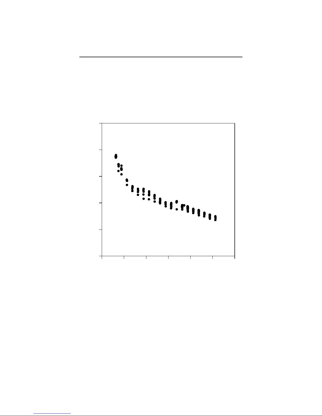
Soil CO2flux measured using a chamber system is dependent on the CO2
concentration in the measurement chamber. This is illustrated in Figure
1-1, which shows typical variations in measured soil CO2flux when the
chamber headspace CO2concentration was allowed to rise. Healy et. al.
(1996) used analytical and numerical models of gas diffusion to evaluate
chamber headspace concentration influence on estimates of soil CO2flux.
They found that chamber-induced perturbations of soil-gas concentration
gradients could result in substantial underestimate of soil CO2 flux (6 to
34% for a 30 minute measurement).
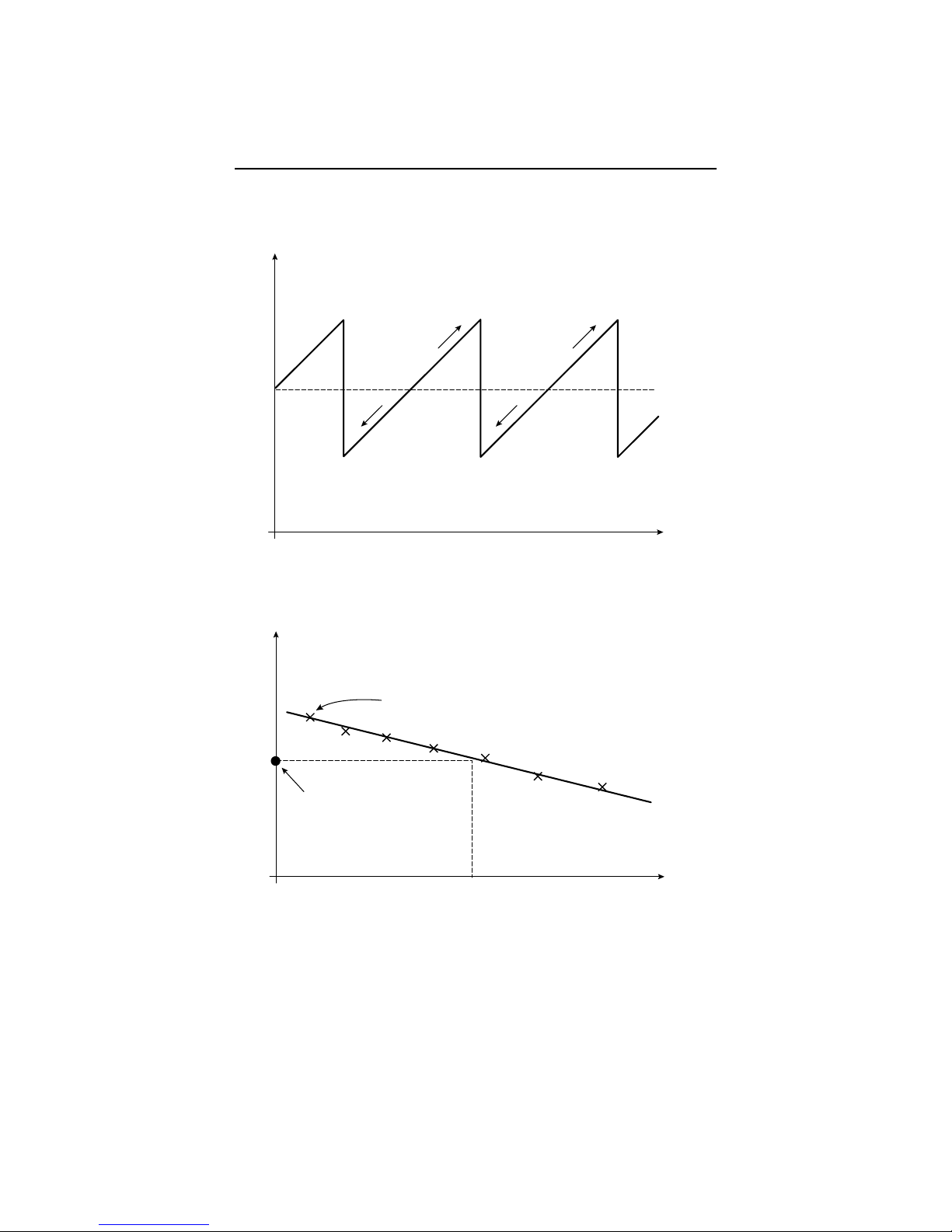
The LI-6400 Soil CO2Flux System has been designed to minimize
perturbation in the soil-gas concentration gradient. Before starting the
measurement, ambient CO2concentration at the soil surface is measured.
Once the chamber is installed, the CO2scrubber is used to draw the CO2in

Section 1
1-2 General Information
the closed system down below the ambient concentration. The scrubber is
turned off, and soil CO2flux causes the CO2concentration in the chamber
headspace to rise (Figure 1-2). Data are logged while the CO2
concentration rises through the ambient level. The software then computes
the flux appropriate for the ambient concentration. This measurement cycle
repeats for as many iterations as you select (Figure 1-3).
Chamber CO
2
Concentration (ppm)
0 400 800 1200 1600 2000 2400
Soil CO
2
Flux (µmol m
-2
s
-1
)
0
4
8
12
16
20
Figure 1-1. Soil CO
2
flux rates depend on the chamber CO
2
concentration.

Section 1
General Information 1-3
CHAMBER
SAMPLE
REF
INLET
IRGA
RS-232
AUXILIARY
Ol
Pressure Relief Fitting
Gas Analyzer
Mixing Fan
LI-6400 Sensor
Head
Analyzer Inlet Duct
Analyzer Outlet Duct
Pressure Relief
Vent Tube
Manifold (CO2Scrub)
Manifold (Analyzer Outlet)
Plumbing Circuit for
CO2Scrub Operation
escape
enter enter
Q
A
Z
1
!@
2#
3$
4
SDF
%
5^
6&
7
GHJK
*
8(
9)
0_
-+
=
L;
:"
'\
space
ctrl
WERTYU I OP {
[}
]
~
|
shift
XCVBNM,
<>
.?
/
shift
Figure 1-2. LI-6400 Soil CO
2
Flux System setup. The shaded plumbing circui
t
is for CO
2
scrub operations and is only used during the draw down portion of
a measurement cycle. During the actual measurement, mixing in the chamber
headspace is achieved with the gas analyzer mixing fan and the associated
plumbing.

Section 1
1-4 General Information
Time
Chamber CO
2
measurement
measurement
A
B
ambient
ambient
Pump off
Pump on
Chamber CO
2
Soil CO
2
Flux
Fluxes computed dring the
measurement phase of each cycle.
Final answer
Regression line
Figure 1-3. (A). Time series of a measurement cycle. Pumping reduced CO
2
air into the
chamber brings the CO
2
below ambient. After the pump turns off, CO
2
rises due to soil CO
2
efflux. During this phase, soil CO
2
flux is computed, and data for regressing flux as a function
of CO
2
is generated. (B). At the end of the measurement cycle, the final flux value is
computed by regressing flux vs CO
2
, and computing the flux that corresponds to the target
(ambient) concentration value.

Section 1
General Information 1-5
Precautions
●Keep the soil chamber shaded to avoid heating.
●If measurements are made on bare soil with no canopy, variation in the
measured flux can occur due to dynamic pressure fluctuations at the
pressure vent outlet caused by wind effects. The vent on the 6400-09 is
shielded to minimize direct wind effects, but you may wish to shield the
entire chamber from the wind.
●If a thin upper layer of soil becomes saturated from short intense rainfall,
a surface gas seal can form that causes CO2concentration to increase
below the saturated layer. A burst of CO2may be released when the
sharp edge of the chamber is inserted, causing excessively high flux
measurements when in actuality the undisturbed flux is very small. The
initial flux from the burst of CO2can be two or more times larger than
the actual flux that would be measured if the chamber were left installed
for several hours without disturbing it. Collars usually provide better
measurements under these conditions because of minimal disturbance;
great care must be taken not to disturb the collars when putting the
chamber onto them, however.
Reference
Healy, Richard W., R.G. Striegl, T.F. Russell, G.L. Hutchinson, and G.P.
Livingston, 1996. Numerical Evaluation of Static-Chamber Measurements
of Soil-Atmosphere Gas Exchange: Identification of Physical Processes.
Soil Sci. Soc. Am. J. 60:740-747.


Attaching the Soil Chamber 2-1
2Attaching the
Soil Chamber
General Description
Figure 2-1 shows an assembled 6400-09, and Figure 2-2 is an exploded
diagram showing the parts of the 6400-09 CO2Flux Chamber. Some of the
individual parts are described in more detail in Section 5. Figure 2-2 also
contains a detailed parts list should you need to order individual parts.
Fig. 2-1. 6400-09 Soil CO
2
Flux Chamber.

Section 2
2-2 Attaching the Soil Chamber
1
2
3
4
56
7
10 89
11
12
13
14
15
16
17
18
20
21
19
Parts List
# Description
1 Fan Inlet Duct
2 Hose Barbs
3 Soil Chamber Adapter Manifold
4 O-rings
5 Radiation Shield
6 Pressure Relief Fitting
7 Mounting Plate
8 Hose Barb (to Air Supply Manifold #15)
9 Hose Barb (open)
10 Soil Probe Holder
11 Pressure Relief VentTube
12 O-ring
13 Mounting Ring
14 O-ring
15 Air Supply Manifold (from pump)
16 Air Supply Manifold (from IRGA)
17 Chamber Body
18 Adjustable Stop Ring
19 Set Screw
Screw
Knob
20 Foam Gasket (for use with PVC soil collar)
21 PVC Soil Collar (optional)
Small
Larger
Largest
Part #
300-02547
192-02597 (2)
192-00225 (2)
192-02889 (1)
6564-171
300-02561
300-02547
300-00567
9860-223
6560-232
192-04095
9860-225
192-04096
9860-226
9860-227
140-04103
236-03742
6560-229
6560-228
Figure 2-2. Exploded view of soil CO
2
flux chamber.

Section 2
Attaching the Soil Chamber 2-3
Attaching the Sensor Head to the 6400-09
To attach the sensor head, follow these steps:
The sensor head handle must be removed to accomodate the 6400-09.
1. Remove the male end of the leaf temperature thermocouple connector
by pulling straight out, and pull the air hose from the underside of the
leaf chamber. Pull the other end of the air hose from the match valve
and replace with the short exhaust tube plug (in the replacement parts
kit).
Figure 2-3. Exhaust tube plug.
2. Unplug the log switch (not used with the soil chamber). If the log
switch wires are threaded underneath the bottom cover of the sensor
head, this cover must be removed to free the log switch.
PAR Sensor
Connector
Log Switch
Connector
+CH
CONST
E
CHROMEL
CONST
E
OMEGA
+
+
Figure 2-4. Unplug the log switch.

Section 2
2-4 Attaching the Soil Chamber
■To remove the bottom cover (if necessary):
a. Turn the sensor head over and remove the 3 Phillips head screws
as shown in Figure 2-5.
LI-6400
PSH-0001
PORTABLE
PHOTOSYNTHESIS SYSTEM
MODEL
SR. NO.
Remove these
3 screws
Sample Air Hose
Hose Barb
Figure 2-5. Remove the 3 Phillips head screws from the bottom of the sensor
head.
b. Remove the hose barbs, if necessary. You may be able to slide the
cover out from underneath the hose barbs; be careful not to
damage the PC board under the cover. If you remove the hose
barbs, note the position of the sample and reference air hoses; the
sample hose is wrapped with a piece of black shrink wrap.

Section 2
Attaching the Soil Chamber 2-5
c. Free the wires.
d. Re-assemble the sensor head bottom cover. Be very careful not to
pinch any wires when replacing the cover.
3. Remove the handle assembly:
a. Unlatch the handle, and unscrew the knurled leaf chamber
adjustment nut (turn clockwise) until it is free of the handle
(Figure 2-6).
Adjustment Nut
Figure 2-6. Turn the adjustment nut clockwise to remove.
b. With the handle latching mechanism in the closed position, wrap
tape or string around the handle (where your hand would normally
be) so that it will stay together. Failure to do so may result in the
rear spring coming out. Leave the handle secured in this manner.
c. Remove the 2 screws (3 on some instruments) on the back side of
the handle, as shown in Figure 2-7, using a #1 Phillips head
screwdriver. Be careful not to lose the spacer that is between the
handle mounting plate and the hinge.

Section 2
2-6 Attaching the Soil Chamber
Remove these
2 (or 3) screws
Handle
Rear View
Quantum sensor
holder
Figure 2-7. Remove the screws on the back side of the handle.
4. Remove the upper half of the leaf chamber.
a. Unhook the connector from the PAR sensor or LED light source, if
necessary.
b. Remove the 2 screws from the hinge on the rear of the upper half
of the leaf chamber (Figure 2-8).
Remove these
2 screws
Quantum sensor
holder
Hinge
Figure 2-8. Remove the 2 screws from the handle hinge.

Section 2
Attaching the Soil Chamber 2-7
NOTE: When removing the soil chamber and reattaching the
handle, the wires to the log switch need not be threaded beneath
the sensor head cover.
c. Remove one fan shroud screw and attach the lamp connector
(Figure 2-9).
CHROMEL
CONST
E
OMEGA
+
+CH
CONST
E
+
Attach lamp connector here
Figure 2-9. Attach the lamp connector to the fan shroud.
5. Remove the lower half of the leaf chamber. There are 8 hex head cap
screws on the optical bench cover, as shown in Figure 2-10. Remove
the cap screws with a 5/64” hex key (in the spares kit). The lower half
of the leaf chamber can now be removed.

Section 2
2-8 Attaching the Soil Chamber
Gasket
Lower leaf
chamber cuvette
Top View
Hex head screws (8)
Figure 2-10. Remove the 8 hex head cap screws.
6. Attach the soil chamber mounting block with the 8 hex head cap
screws from the previous step. The proper orientation of the mounting
block is shown in Figure 2-11. Note the thin vinyl gasket on the top
surface of the optical bench (Figure 2-11). This gasket is reusable; it
should adhere to the optical bench, but if it becomes detached, be sure
to reposition it before attaching the mounting block. Tighten the 8
screws carefully and evenly.
CHROMEL
CONST
E
OMEGA
+
Soil Chamber Mounting Block
Vinyl Gasket
Figure 2-11. Attach the mounting block to the sensor head.
7. Make sure all O-rings are properly positioned, as shown in Figure 2-12.

Section 2
Attaching the Soil Chamber 2-9
O-rings (5)
Cap screws (4)
#192-02597 (2)
#192-00225 (2)
#192-02889 (1)
Figure 2-12. Location of O-rings and cap screws.
8. Attach the 6400-09 body to the sensor head/mounting block assembly
using the 4 cap screws (use the 5/64" hex key included), located on
each corner of the mounting block (Figure 2-13).

Section 2
2-10 Attaching the Soil Chamber
CHROMEL
CONST
E
OMEGA
+
+CH
CONST
E
+
Soil Chamber Mounting Block
Male Thermocouple
Connector
Female Thermocouple
Connector
Figure 2-13. Attach the 6400-09 body to the mounting block.
9. Connect the male and female ends of the thermocouple connectors.
10. Join the sample and reference tubes on the sensor head with the "U"
shaped piece of tubing, in the 6400-09 replacement parts kit (Figure 2-
14).
LI-6400
PSH-0001
PORTABLE
PHOTOSYNTHESIS SYSTEM
MODEL
SR. NO.
Exhaust plug
Sample and reference
tubing connector
Figure 2-14. Insert exhaust plug and sample and reference tube junction as shown.
Table of contents
Other LI-COR Laboratory Equipment manuals

LI-COR
LI-COR LI-6400 User manual

LI-COR
LI-COR LI-6800 User manual

LI-COR
LI-COR LI-8100 User manual

LI-COR
LI-COR LI-6800 User manual

LI-COR
LI-COR Odyssey User manual

LI-COR
LI-COR LI-6400 User manual

LI-COR
LI-COR LI-6400 User manual

LI-COR
LI-COR Odyssey CLx User manual

LI-COR
LI-COR Odyssey XF User manual

LI-COR
LI-COR Odyssey M 3340 User manual
Popular Laboratory Equipment manuals by other brands

Belden
Belden HIRSCHMANN RPI-P1-4PoE installation manual

Koehler
Koehler K1223 Series Operation and instruction manual

Globe Scientific
Globe Scientific GCM-12 quick start guide

Getinge
Getinge 86 SERIES Technical manual

CORNING
CORNING Everon 6000 user manual

Biocomp
Biocomp GRADIENT MASTER 108 operating manual