Amsco RELIANCE 300 User manual

UNCRATING/INSTALLATION INSTRUCTIONS
RELIANCE® 300
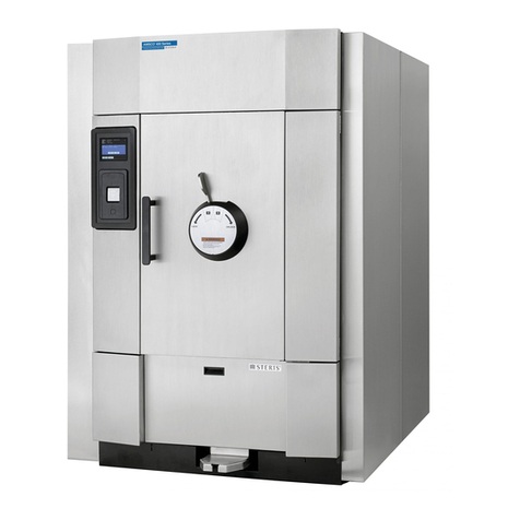
Laboratory Glassware Washer
(12/98) P-122993-618
Rev. 1

LIMITATIONS OF LIABILITY AND INDEMNITY
IN NO CASE, WHETHER AS A RESULT OF A BREACH OF CONTRACT, BREACH OF WAR-
RANTY OR TORT (INCLUDING STERIS'S OR CUSTOMER'S WILLFUL ACTS OR NEGLIGENCE
OR STRICT LIABILITY) SHALL STERIS OR CUSTOMER BE LIABLE TO THE OTHER FOR ANY
CONSEQUENTIAL OR INCIDENTAL DAMAGES INCURRED BY THE OTHER, INCLUDING, BUT
NOT LIMITED TO, LOSS OF REVENUE, PROFITS OR GOODWILL. HOWEVER, NOTHING
CONTAINED IN THIS AGREEMENT IS INTENDED TO RELIEVE EITHER STERIS OR CUS-
TOMER FROM CLAIMS, LIABILITY, DAMAGES OR EXPENSES RESULTING FROM BODILY
INJURY, INCLUDING DEATH, OR FROM PROPERTY DAMAGE INCURRED DUE TO THE
WILLFUL ACTS, THE NEGLIGENCE OF OR THE STRICT LIABILITY OF THAT PARTY.
STERIS AGREES TO DEFEND, INDEMNIFY AND HOLD CUSTOMER HARMLESS FROM ANY
AND ALL CLAIMS, LIABILITY, DAMAGES OR EXPENSES DUE TO PERSONAL INJURIES,
INCLUDING DEATH, TO EMPLOYEES OF STERIS AND CUSTOMER AND TO THIRD PARTIES
AND FOR PROPERTY DAMAGE TO THE EXTENT OF THE WILLFUL ACTS OF THE NEGLI-
GENCE OF STERIS OR THE STRICT LIABILITY OF STERIS CAUSED BY THE ACTS OR
OMISSIONS OF STERIS. CUSTOMER AGREES TO DEFEND, INDEMNIFY AND HOLD STERIS
HARMLESS FROM ANY AND ALL CLAIMS, LIABILITY, DAMAGES OR EXPENSES DUE TO
PERSONAL INJURIES, INCLUDING DEATH, TO EMPLOYEES OF CUSTOMER AND STERIS
ANDTOTHIRDPARTIESANDFROMPROPERTYDAMAGETOTHEEXTENTOFTHEWILLFUL
ACTS OR THE NEGLIGENCE OF CUSTOMER OR THE STRICT LIABILITY OF CUSTOMER
CAUSED BY THE ACTS OR OMISSIONS OF CUSTOMER.
WARNING - COPYING PROHIBITED
This manual is protected by Federal Copyright Law, which
provides for damages of up to $20,000, as well as
criminal fines and imprisonment, for unauthorized copying.

i
Table of Contents Uncrating/InstallationInstructions 122993-618
AWORDFROMSTERIS CORPORATION
Follow each step of the uncrating/installation instructions in the
order presented. Open the carton carefully to avoid damage
totheequipmentinside. Ifyoufindanyindicationofdamagetothe
equipment (no matter how slight), show it to your supervisor.
To properly install this unit, you will need the Equipment Drawings
(previously furnished), showing all utility service and space re-
quirements. If drawings cannot be located, replacement copies
may be obtained by writing, wiring, faxing or telephoning STERIS
giving the serial, equipment and model numbers of your washer.
Once installed, washer operation should be tested by a STERIS-
trained service technician prior to your usage of the equipment.
If STERIS supervision is desired for installing and starting up this
equipment, contact the STERIS Regional Office nearest you.
The Reliance®300 Laboratory Glassware Washer is designed for
efficient cleaning of laboratory glassware, plasticware and metal
goods typically used in research, support production and quality
control laboratories. This washer is specifically designed to only
processgoodsasoutlinedintheOperatorManual(P-122993-619).
Ifthereisanydoubtaboutaspecificmaterialorproduct,contactthe
manufacturer of the product for the recommended washing
technique.
Asummaryofthesafetyprecautionstobeobservedwhenuncrating,
installingandtestingthiswashercanbefoundinSection1ofthese
instructions. Donotbegin uncrating/installing thisequipment until
you have become familiar with this information.
IMPORTANT: Be sure to check the Occupational Health and
Safety Act, as well as local electric and plumbing codes, for any
special requirements that may pertain to installation of this unit.
©1998, STERIS Corporation. All rights reserved.
Indications for Use
Advisory

iii
Table of Contents Uncrating/InstallationInstructions 122993-618
TABLE OF CONTENTS
SECTIONSECTION
SECTIONSECTION
SECTION TITLETITLE
TITLETITLE
TITLE PAGEPAGE
PAGEPAGE
PAGE
1 SUMMARY OF WARNINGS AND CAUTIONS...... 1
2 UNCRATING INSTRUCTIONS ............................ 3
Open Carton ......................................................................3
Move Washer and Remove Skid .......................................4
Prepare Washer for Installation .........................................4
3 INSTALLATION INSTRUCTIONS ....................... 5
Before Installing Equipment...............................................5
Connect Utilities.................................................................5
Cleanup..............................................................................6
4 INSTALLATION CHECKLIST.............................. 7
5 OPERATIONAL TEST ......................................... 9

1
Uncrating/InstallationInstructions 122993-618
The following is a summary of the safety precautions which must be observed when uncrating, installing and
operatingthis equipment. WARNINGS indicatethe potentialfordanger topersonnel and CAUTIONSindicate the
potential for damage to equipment. These precautions are repeated (in whole or in part), where applicable,
throughout the instructions.
WARNING-PERSONALINJURYAND/OREQUIPMENTDAMAGEHAZARD:
When moving the unit, use a forklift. Do not use door(s) or door handle(s) for lifting.
WARNING-LACERATION/EYEINJURYHAZARD:
When removing bands, wear eye protection and always use a tool specifically designed to cut the bands.
The bands used to secure this carton can cause personal injury when cut and tension is released.
WARNING-LACERATIONHAZARD:
When removing bolts, wear gloves to protect your hands.
WARNING-BURNHAZARD:
Whencheckingtheautomaticstopfeature,wearglovesandfaceprotectionandopenchamberdoorslowly.
Hot water/steam may be sprayed through door opening if door is opened during a cycle.
When blowing out utility supply lines, wear gloves, face shield and protective clothing.
WARNING-PERSONALINJURYHAZARD:
Whenclosingchamberdoor,usedoorhandle. Keepfingers/handsawayfromtopandsidesofdoortoprevent
fingersfrombeing crushed.
WARNING-FALLHAZARD:
To prevent falls, keep floors dry. Promptly clean up any spills or drippage.
CAUTION-POSSIBLEEQUIPMENTDAMAGE:
After utilities are connected to washer, slowly remove the protective adhesive paper from the exterior
cabinet panels to reduce the level of static discharge.
When removing adhesives from stainless steel, use a small amount of non-flammable cleaning solvent.
Rub in a back-and-forth motion (in same direction as surface grain). Solvent rubbed in a circular motion
orappliedwithawirebrushorsteelwoolondoorandchamberassembliescanbeharmfultostainlesssteel.
Do not use solvents on painted surfaces.
Oncethree-phasepowerisconnected,checkpumpforcorrectrotation. Incorrectpumprotationmayresult
in pump damage and improper cleaning action.
Before operating unit, always position each manifold over a manifold connector. If manifolds are not
positioned correctly, damage may result and unit will be unable to effectively wash loads.
1
SUMMARY OF WARNINGS AND CAUTIONS
Summary of Warnings and Cautions

2
122993-618 Uncrating/InstallationInstructions
Figure 1. Remove BandsFigure 1. Remove Bands
Figure 1. Remove Bands
Nails
Top
Carton
Bands
Figure 2. Remove Packing MaterialFigure 2. Remove Packing Material
Figure 2. Remove Packing Material
Polystyrene
Wrap
Cardboard Corners
Bands
Skid
UncratingInstructions
Figure 3. Reliance 300 Laboratory Glassware WasherFigure 3. Reliance 300 Laboratory Glassware Washer
Figure 3. Reliance 300 Laboratory Glassware Washer
Door Handle
Control Panel
Lower Service
Access Panel

3
Uncrating/InstallationInstructions 122993-618
NOTE: Washer weighs approximately 800 lbs (363 kg). Use a
forklift to move the unit.
NOTE:Uncrateonlevelfloorasclosetoinstallationsiteaspossible.
1. Positionunit toopen cardboardcartonfrom thetop. Provide a
clear work area on all sides.
2. Carefully cut and remove bands from carton (see Figure 1).
3. Discardbandsbeforecontinuing.
4. Lift off cardboard top.
5. Remove nails attaching cardboard to skid.
6. Pull cardboard carton away from unit. Discard carton.
7. Carefully cut and remove second set of bands (see Figure 2).
8. Discardbandsbeforecontinuing.
9. Removeanddiscardcardboardcornersandpolystyrenewrap
from around unit (see Figure 2).
NOTE: Do not remove protective adhesive paper from the exterior
cabinet panels until after utilities are connected.
10. Locate keys for the lower service access panel.
11. Remove lower service access panel and check tip indicator,
located inside lower service compartment (see Figure 3). Tip
indicator contains a blue compound at the bottom of the
indicator. If unit has been tipped, residue from the blue
compound will be found higher up in the indicator.
If unit was tipped, notify STERIS regional office. A service
technician will review the equipment and determine if unit was
damaged.
12. Re-install lower service access panel.
Open Carton
WARNING - PERSONAL INJURY
AND/OR EQUIPMENT DAMAGE
HAZARD: When moving the unit,
usea forklift. Do notuse door(s) or
door handle(s) for lifting.
WARNING - LACERATION/EYE IN-
JURY HAZARD: When removing
bands, wear eye protection and al-
ways use a tool specifically de-
signedtocutthebands. Thebands
usedtosecurethiscartoncancause
personal injury when cut and ten-
sion is released.
2
UNCRATING INSTRUCTIONS
UncratingInstructions

4
122993-618 Uncrating/InstallationInstructions
1. With washer still mounted on skid, use a forklift to move washer
to installation site.
2. Remove four lag bolts securing washer base to the skid.
3. Removeanddiscardskidfromunderwasher. Ifnecessary,use
a piece of plywood as a small ramp to slide washer from skid to
floor.
4. Position washer in final location. Use tubing as rollers and roll
the washer into position.
UncratingInstructions
Move Washer and
Remove Skid
WARNING - PERSONAL INJURY
AND/OR EQUIPMENT DAMAGE
HAZARD: When moving the unit,
useaforklift. Donotusedoor(s)or
door handle(s) for lifting.
WARNING - LACERATION HAZ-
ARD: When removing bolts, wear
gloves to protect your hands.
NOTE: Do not remove protective adhesive paper from the exterior
cabinet panels until after utilities are connected.
1. Open chamber door. If accessories are ordered with unit,
remove nylon straps securing accessories to chamber frame
and slide accessories out of wash chamber.
2. Remove Operator Manual from wash chamber. Make sure
appropriateperson receives OperatorManual.
3. Remove nylon straps securing rotary spray arm assembly at
top of wash chamber.
4. Remove tape securing debris screen and manifold connector
in bottom of wash chamber (sump).
5. Removetapeblockingthesumpdrainopening,locatedunder
the sump heating coil or electric heating element.
6. Closechamberdoor.
7. Discard all packing material removed during uncrating
procedures.
Prepare Washer for
Installation
WARNING - PERSONAL INJURY
HAZARD: When closing chamber
door, use door handle. Keep fin-
gers/hands away from top and
sides of door to prevent fingers
from being crushed.

5
Uncrating/InstallationInstructions 122993-618
1. Review installation requirements:
a. Clearance-ClearancespaceshownonEquipmentDrawingis
necessary for easy installation and proper operation and
maintenance of washer.
b. Barrier wall flange(s) installation - Refer to Equipment Draw-
ing for barrier wall installation.
c. Utility service lines:
•Toallow serviceon unitwithout shuttingoff buildingsupply
lines, shutoff valves (not by STERIS) should be installed on
steam, air and water lines to unit (see Figure 4). Shutoff
valvesmustbecapableofbeinglockedintheOFFposition
only.
•Disconnect switch (not by STERIS) must be installed in
electricsupplylinenearwasher(seeFigure4). Disconnect
switchmustbecapableofbeinglockedintheOFFposition
only.
•If this machine is installed next to other equipment, shutoff
valves and disconnect switch should be located so that
servicecanbeshutofftoonepieceofequipmentatatime.
•Utility service requirements are shown on Equipment
Drawing.Thismachinerequireseither120/208volts,60Hz,
3-phase,4-wire;or480volts,60Hz,3-phase,3-wirepower.
Check Equipment Drawing or Identification Plate (located
inside lower service compartment on bottom of chamber
sump, see Figure 3) for proper voltage.
•Blow out all utility supply lines to remove chips, scale, etc.
2. Make sure washer is placed, as shown on Equipment Drawing,
in correct relation to building supply lines. If unit is not at
installation site, refer to Uncrating Instructions (Section 2) for
proper moving instructions.
3. Check level of washer.
•Place a spirit level on top and along side of washer cabinet.
•Levelwasher,end-to-endandside-to-side,usinglevelinglegs
located at base of washer.
1. Unlock and remove lower service access panel.
2. Connect the following building supply lines to the washer (see
Figure 5).
•HOTWATER -Connect linetowasherconnection, accessible
from lower service compartment.
NOTE: Water is hot; safely run water line to a sink or drain.
Before Installing
Equipment
Figure 4. Utility ServiceFigure 4. Utility Service
Figure 4. Utility Service
ConnectionsConnections
Connections
InstallationInstructions
INSTALLATION INSTRUCTIONS
WARNING-BURNHAZARD: When
blowing out utility supply lines,
wear gloves, face shield and pro-
tective clothing.
Connect Utilities
3
Lock

6
122993-618 Uncrating/InstallationInstructions InstallationInstructions
•COLDWATER(required onlyifequippedwithDrainDischarge
Cooldown and Cold Water Pre-wash option) - Connect line to
washer connection, accessible from lower service com-
partment.
•STEAM (required on Steam Heated units only) - Connect line
to washer connection, accessible from lower service
compartment.
NOTE: Live steam; safely direct steam discharge to an open
drain.
•CONDENSATE RETURN (required on Steam Heated units
only) - Connect building condensate return line to washer
connection, accessible from lower service compartment.
Condensate return must be vented and non-pressurized.
•DRAIN - Connect building waste line to washer drain line,
accessible from lower service compartment.
•VENT - Connect building ventilation system to washer vent
connection, accessible from top of washer.
•PURE WATER- Connect building supply line to washer
connection, accessible from lower service compartment.
•AIR - Connect building supply line to washer connection,
accessible from lower service compartment.
•ELECTRIC - Connect building electrical supply to washer
junction box, accessible from lower service compartment.
Verify tight electrical connections.
3. Open building supply valves and check for leaks. Correct if
necessary.
1. Re-install and lock lower service access panel.
2. Remove all protective paper from the washer cabinet panels.
Slowly peel paper away from stainless steel to reduce the level
ofstaticdischarge.
3. Remove any adhesive found on panels, door(s) and inside
chamber with a small amount of non-flammable cleaning sol-
vent. Keep solvent away from all painted surfaces or damage
may result.
4. Inspectwasherandworkareatobesureallmaterialsusedduring
installation have been removed.
THISCOMPLETESTHEINSTALLATION. Beforeoperatingequip-
ment, confirm that all items on Installation Checklist (Section 4)
have been satisfactorily implemented and Operational Test (Sec-
tion 5) is conducted by a qualified service technician.
Condensate
Return
Figure 5. Washer ConnectionsFigure 5. Washer Connections
Figure 5. Washer Connections
Cleanup
CAUTION: After utilities are con-
nected to washer, slowly remove
theprotectiveadhesivepaperfrom
the exterior cabinet panels to re-
duce the level of static discharge.
CAUTION: When removing adhe-
sives from stainless steel, use a
small amount of non-flammable
cleaning solvent. Rub in a back-
and-forth motion (in same direc-
tion as surface grain). Solvent
rubbed in a circular motion or ap-
plied with a wire brush or steel
wool on door and chamber assem-
blies can be harmful to stainless
steel. Do not use solvents on
painted surfaces.
Vent
Pure
Water
Air
Electric
Hot Water Steam
Cold Water
Drain

7
Uncrating/InstallationInstructions 122993-618
4
INSTALLATION CHECKLIST
Installation checklist must be completed after the washer is in-
stalled and prior to performing the operational test to assure
complete and correct installation.
NOTE: Contact your STERIS sales representative to demonstrate
proper equipment operation and schedule a technician to test your
installation.
❏Shutoff valves (not by STERIS), for maintenance purposes and
capableofbeinglockedinOFFpositiononly,installedonsteam,
air and water lines and in compliance with local codes, OSHA
standards,etc.
❏Disconnectswitches(notbySTERIS),capableofbeinglockedin
OFFpositiononly,installedinelectricalsupplylinesneartheunit
and in compliance with local codes, OSHA standards, etc.
NOTE: Ifunitisinstallednexttootherequipment,shutoffvalvesand
disconnect switches should be located so that service can be shut
off to one piece of equipment at a time.
❏Washer positioned, as shown on Equipment Drawing, with re-
quired clearance space and in relation to building supply lines.
❏Washer is level.
❏If washer is equipped with Drain Discharge Cooldown and Cold
WaterPre-washoption,buildingcoldwaterlinesupplieswaterto
unitatdynamicpressureandtemperatureasspecifiedonEquip-
ment Drawing.
❏Buildinghotwaterlinesupplieswatertounitatdynamicpressure
and temperature as specified on Equipment Drawing.
❏If Steam Heated unit, building steam line provides steam to unit
at dynamic pressure as specified on Equipment Drawing.
❏IfSteamHeatedunit, buildingcondensatereturnlineisconnect-
ed to washer as specified on Equipment Drawing.
❏Pure water line supplies water to unit at dynamic pressure as
specified on Equipment Drawing.
❏Buildingairlinesuppliesairtounitatstaticpressureasspecified
on Equipment Drawing.
❏Building waste line is connected to washer as specified on
EquipmentDrawing.
❏Building ventilation system is connected to washer as specified
on Equipment Drawing.
❏Electrical supply for unit is as specified on Equipment Drawing.
❏Floor surrounding unit has non-slip surface.
InstallationChecklist

9
Uncrating/InstallationInstructions 122993-618
STATUS
STATUS
STATUS
OPERATIONALTEST
Operational Test
Testproceduresincludedinthissectionshouldbeperformedbya
qualifiedservicetechnicianpriortonormaloperationofthewasher.
1. Open chamber door. Check that debris screen is positioned in
washchambersump.
2. Checkthatwashchamberisemptyandallpackingmaterial(tape
and nylon straps) has been removed.
3. Remove manifold connector and inlet filter from bottom of wash
chamber.
4. Unscrew rotary spray holder and lower the rotary spray arm
assemblyfrom top ofwash chamber. Removerotary spray arm
assembly from chamber.
NOTE: There is a loose bushing between the rotary spray hub
and top of wash chamber. When lowering rotary spray arm
assembly, bushing will fall. Be sure to hold onto bushing while
removing and lowering rotary spray arm assembly.
5. Close chamber door. Make sure main power switch, located in
upper service compartment (see Figure 3), is in ON position.
6. PressPower-Off/StandbyTouchPadonce(seeFigure6). Verify
that model name temporarily appears on the display screen,
* RELIANCE *
* MODEL 300 *
followed by the first cycle menu screen:
LIGHT MEDIUM
HEAVY CYCLE 4
Indicates flashing position.
7. PressCycle/StarttouchpadoncetoselecttheLIGHTcycle.
Verify name of selected cycle appears on display screen.
PRESS START TO
PROCESS - LIGHT
NOTE: Pressing Cycle/Start once will select the cycle corre-
sponding to the cycle name flashing on the display screen.
WARNING - PERSONAL INJURY
HAZARD: When closing chamber
door, use door handle. Keep fin-
gers/handsawayfromtopandsides
of door to prevent fingers from
being crushed.
Figure 6. Control PanelFigure 6. Control Panel
Figure 6. Control Panel
CHANGE
VALUES
CYCLE STATUS
CYCLE
MENU SELECT
CYCLE REVIEW
CYCLE CYCLE
START STOP
RESET
EXTEND
CYCLE
POWER OFF/
STANDBY
ALARM
REPLY SERVICE
MODE
PROGRAM
CURSOR VALUE SAVE
VALUES
5

10
122993-618 Uncrating/InstallationInstructions Operational Test
CAUTION: Once three-phase
power is connected, check pump
forcorrectrotation. Incorrectpump
rotation may result in pump dam-
age and improper cleaning action.
WARNING-BURNHAZARD: When
checking the automatic stop fea-
ture, wear gloves and face protec-
tionandopenchamberdoorslowly.
Hot water/steam may be sprayed
through door opening if door is
opened during a cycle.
WARNING - FALL HAZARD: To
prevent falls, keep floors dry.
Promptly clean up any spills or
drippage.
CAUTION: Before operating unit,
always position each manifold or
accessory header over a manifold
connector. If manifolds or acces-
sory headers are not positioned
correctly, damage may result and
unit will be unable to effectively
wash loads.
WARNING - PERSONAL INJURY
HAZARD: When closing chamber
door, use door handle. Keep fin-
gers/hands away from top and
sides of door to prevent fingers
from being crushed.
8. PressCycle/Starttouchpadasecondtimetostarttheselected
(LIGHT) cycle.
NOTE: If Cycle/Start is not pressed a second time while the
selectedcycle nameis displayed,screen automaticallyreturnsto
the cycle menu.
9. Checkthatpurewaterstoragetank(optional)beginstofillassoon
as the cycle is started. If not, contact a STERIS service techni-
cian. Check that tank does not overfill.
10. Once chamber sump is filled with water, check rotation of the
recirculation pump as follows:
a. Unlock and remove lower service access panel.
b. While viewing the pump motor shaft, alternately press the
Cycle/StartandStop/Resettouchpads.
c. Verifymotorshaftisrotatingindirectionindicatedbythearrow
onthemotorhousing. Ifpumpisrotatinginthewrongdirection,
disconnect main 3-phase power, reverse any two 3-phase
wires, reconnect power and check shaft rotation.
d. Re-install and lock lower access panel.
11. Wearing the proper safety protection (gloves and face shield),
check automatic stop feature as follows:
a. Beingcarefulofhotwaterescaping,openchamberdoorduring
Pre-wash treatment. Verify that all services to the wash
chamberareautomaticallyshutoff. PressAlarmReplytouch
pad to silence alarm buzzer. Close chamber door.
12. PressStop/Resettouchpadandopenchamberdoor.
13. Remove and clean debris screen under running water. Replace
screen in chamber sump.
14. Placebushingontopofrotarysprayhubandreattachrotaryspray
arm assembly to top of wash chamber.
15. Replace inlet filter and manifold connector.
16. Insert empty manifold into wash chamber.
17. ClosechamberdoorandpressCycle/Starttouchpadtoresume
cycleoperation.
18. Inspectpiping,insideandlowerservicecompartments,forleaks.
If any leaks occur, tighten appropriate hose clamp connections
andunions.
19. Allow cycle to run to completion. Use the Operator Manual
provided to verify proper unit and cycle operation.

11
Uncrating/InstallationInstructions 122993-618Operational Test
STATUS
20. Verifyalarmbuzzersoundsandthefollowingoperatorinstruction
appearsondisplay screenoncecycle iscomplete.
PLEASE OPEN DOOR
AND REMOVE LOAD
21. Openchamberdoorandallowchamberandaccessoriestocool
before unloading. Verify display screen returns to the first cycle
menu once door is opened.
22. Remove screens from utility supply-line strainers and check for
debris. Clean screens if necessary.
WASHERISNOWREADYFORNORMALOPERATION. Contact
your local STERIS representative for a demonstration on how to
operate the equipment. Refer to the
Operator Manual (P-122993-
619)
for washer operating instructions.

12
122993-618 Uncrating/InstallationInstructions
NOTES

The best way to prevent costly downtime due to equipment malfunction is with
regularlyscheduledmaintenanceperformedbyqualifiedtechnicianstrainedinthe
latesttechnology.STERIS offers annualmaintenanceagreements to giveyour capital
equipmentplanned maintenancethat willhelpcorrectlittleproblems beforethey
becomebigones.STERISEngineeringServicecombinestheprecisemaintenance
programandfactory-trained techniciansto assure youof maximum productivity.
Our STERIS service technicians thoroughly inspect, clean, adjust and provide all
necessarymaintenancetokeepyourequipmentperformingaccordingtofactoryspeci-
fications, all at an established economical rate that you can plan for.
Wehave morethan 5,000customers whoare benefitingfrom STERISmaintenance
agreements.Why not jointhem? Obtaincomplete details bycalling 1-800-333-8828,or
writing to:
Protect your STERIS equipment with
cost-effective extended service agreements
Table of contents
Other Amsco Laboratory Equipment manuals

Amsco
Amsco Century Series Instructions for use

Amsco
Amsco RELIANCE 444 HTM User manual

Amsco
Amsco Century User manual

Amsco
Amsco C Series User manual

Amsco
Amsco 110LS User manual

Amsco
Amsco HC-600 User manual

Amsco
Amsco STERIS User manual

Amsco
Amsco Evolution Series User manual

Amsco
Amsco EAGLE SERIES 3021 Installation and user guide

Amsco
Amsco 400 Series User manual
Popular Laboratory Equipment manuals by other brands

Thermo Scientific
Thermo Scientific RT Basic 12 Operation manual

deffner & Johann
deffner & Johann RCM 5717 operating manual

Varian
Varian Micro-GC 490-GC user manual

XD XCLUSIVE
XD XCLUSIVE Rena P301.13 Series manual

Hanna Instruments
Hanna Instruments HI 4008 instruction manual

Analytik Jena
Analytik Jena UV lamp operating manual