Start up Guide for Axpert-VT240S Series AC Drive
1
Introduction
This Start-Up Guide is not meant to replace the compete Instruction Manual. This is a
supplementary document intended to provide concise instructions covering the most common
installation and configuration options. For detailed instructions, safety precautions, proper
mounting, installation, configuration and operation, please refer to the appropriate revision of
the Axpert-VT240S complete Instruction Manual.
WARNING: Only qualified personnel should plan or implement the installation, start-up,
operation and maintenance of this equipment. Personnel must read the entire INSTRUCTION
MANUAL before attempting to install, operate or troubleshoot the Axpert-VT240S.
There are ten key elements to the basic installation and start up of a Variable Frequency Drive. In this
Start-Up Guide we will cover the following steps. For more information, please refer to the complete
Instruction Manual.
1. Physically install the VFD with consideration for ambient temperature and proper cooling, adequate
room around the VFD for airflow and mounting properly to protect the VFD for the specific environment.
If mounted inside or outside of another enclosure, make sure the environment that the VFD is mounted
in is properly evaluated and the correct NEMA rated drive or enclosure is used to suit the application.
For example, if outside, a NEMA3R, clean room, NEMA1 or IP20, a dirty, dusty environment, a
NEMA12.
2. Check that the VFD is of the correct voltage and current rating to suit the application.
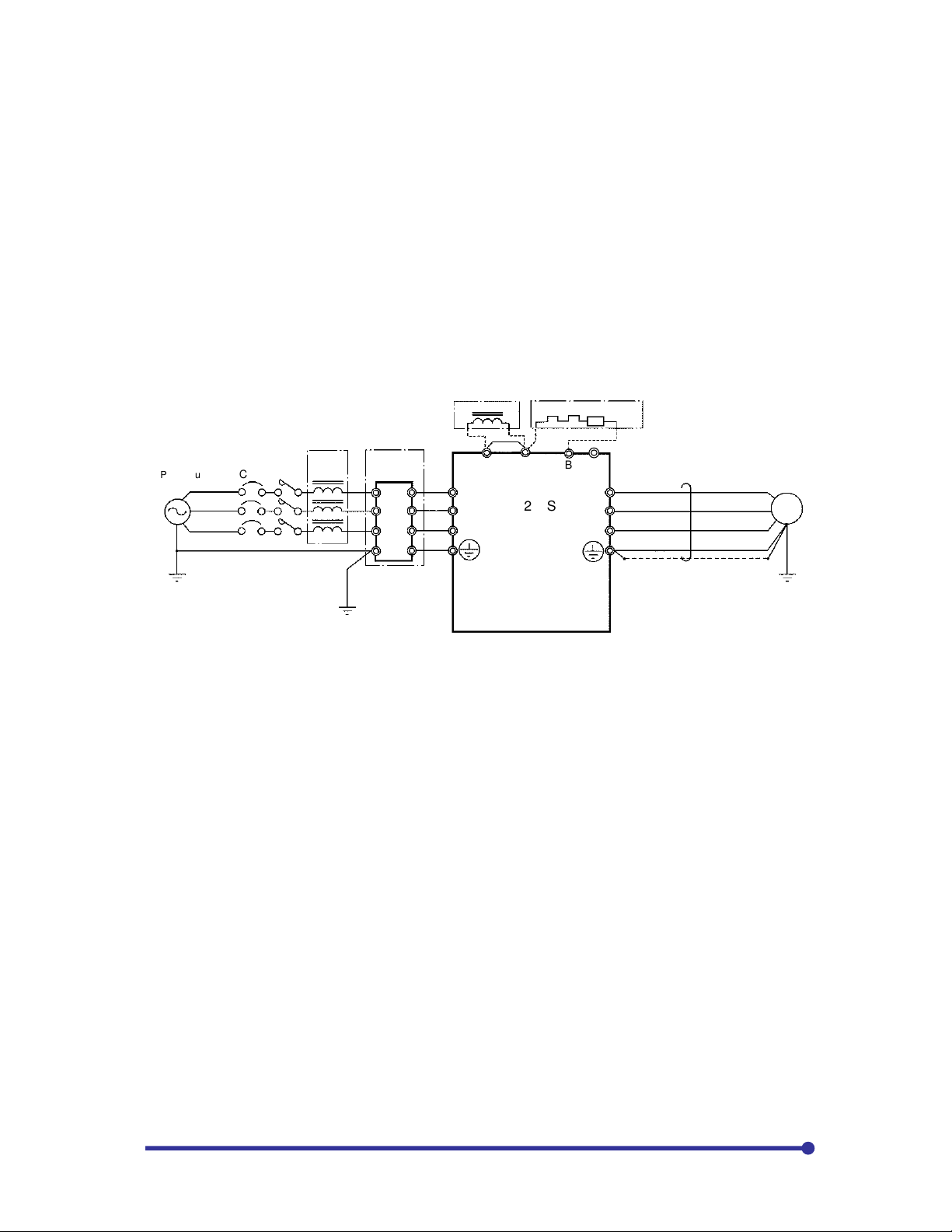
3. Use the required peripheral devices, such as Circuit Breaker or Input Fuses, Line or Load reactors,
DC Bus choke, DB resistors, push buttons and selector switches to suit the application.
4. Connect the AC input voltage, AC motor and control wiring using proper sized cables and wires with
appropriate grounding and shielding to assure proper operation. Make sure that the requirements of
the local electrical codes are adhered to for a proper installation.
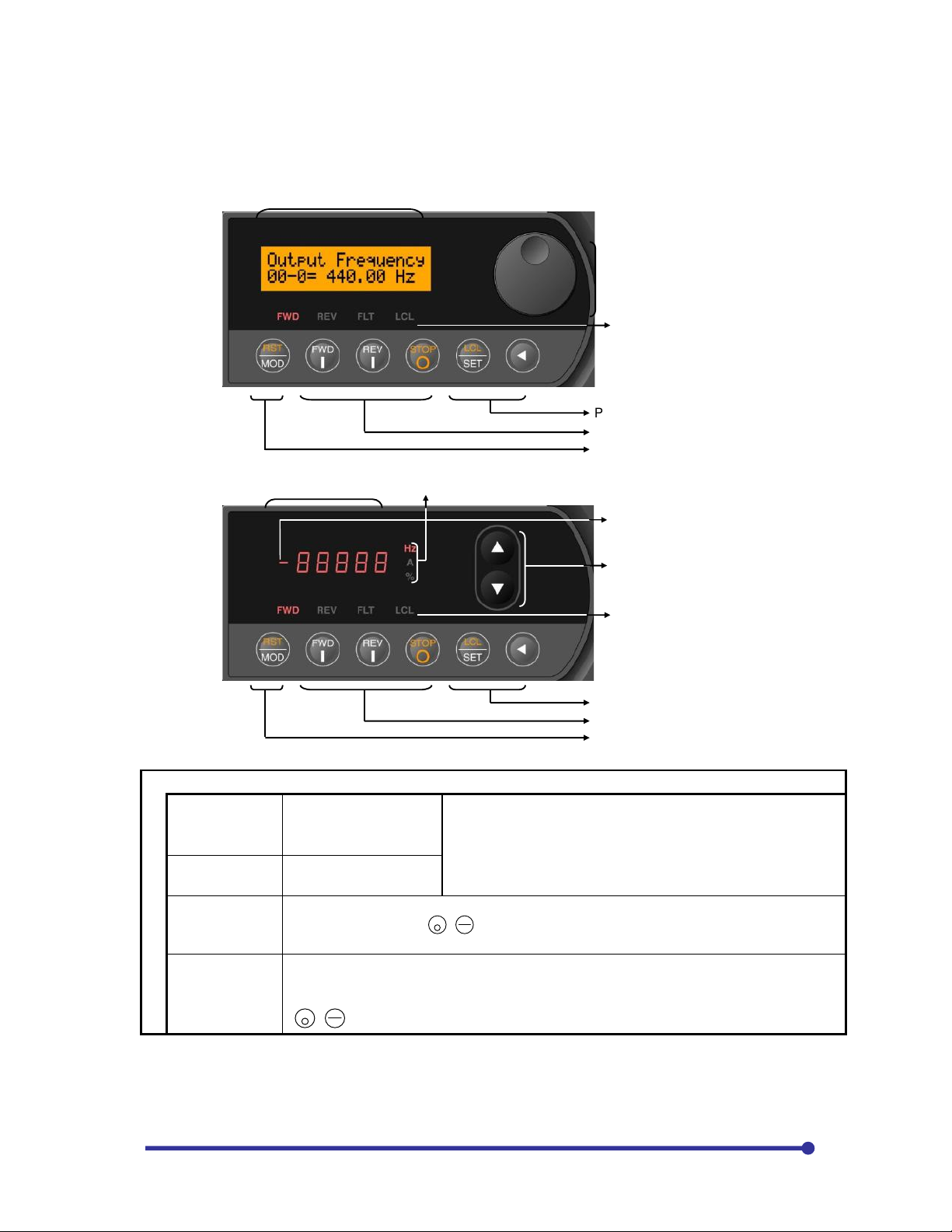
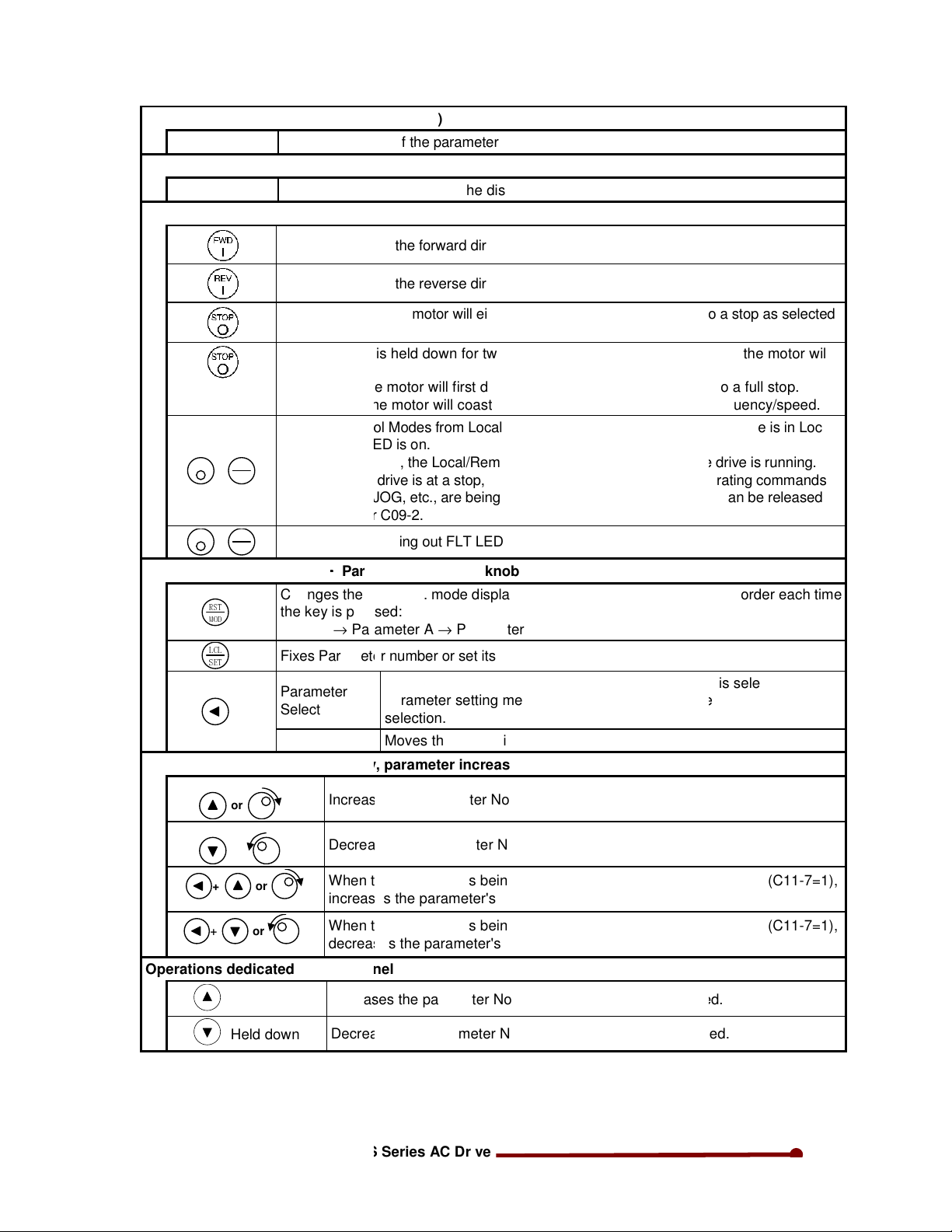
5. Power up the VFD and familiarize yourself with the operation of the keypad, such as navigating
through the parameters and how to change parameters.
IMPORTANT NOTE! Whenever undertaking the start-up of a VFD, especially if anyone has been
operating the VFD prior to the start-up, it is advisable to set all of the parameter values to their
factory default values. By knowing that all of the parameters are at the default values, this can
save a lot of troubleshooting later on through mis-operation by having a parameter set to a
value not needed by the application. An incorrectly programmed parameter can look like a
defective VFD. Setting parameter C09-7 to “9” will reset all user parameters to default. If drive is
supplied with some logic, ensure that you have related parameter list to input after default.
6. Review the parameters and determine which ones need to be changed to meet the requirements of
your application. The motor parameters (B00-0 to B00-7 for v/f control and B01-0 to B01-7 for vector
control mode) must be entered for precise protection of the AC motor used. The method for start/stop,
speed reference, and values for the Accel/decel rate and minimum and maximum speeds are all
important parameters to be considered.
7. Start the motor and assure proper rotation and the expected load currents are displayed, (See
Parameter D02-0 - Output Current in Amps). Find the read-only parameters that display information
like a digital meter to show operational parameters such as input and output voltages, DC Bus voltage,
load currents, motor speed and frequency, power used and run time.
8. Review the Fault Codes and what they mean. Look at the Fault History parameters and how the
VFD will display the last ten faults and operational values that existed at the time of the fault.
9. Test all of the system operators, such as pushbuttons, remote keypad, selector switches, to assure
proper operation and control. Verify starting and stopping and correct speed control.
10. Once the installation is complete and the system operates as desired, It is advised to fully
document all parameter value changes, jumper changes and control wiring to simplify troubleshooting
or system duplication in the future. This will help to get better technical support if need arises.