AMX Encore User manual

instruction manual
Landmark Products
Encore

Limited Warranty and Disclaimer
AMX Corporation warrants its products to be free from defects in material and workmanship under normal use for a
period of three years from date of purchase from AMX Corporation, with the following exceptions. Electrolumines-
cent and LCD control panels are warranted for a period of three years, except for the display and touch overlay com-
ponents which are warranted for a period of one year. Disk drive mechanisms, pan/tilt heads, power supplies,
modifications, MX Series products, and KC Series products are warranted for a period of one year. Unless otherwise
specified, OEM and custom products are covered for a period of one year. AMX Corporation software products are
warranted for a period of 90 days. Batteries and incandescent lamps are not covered.
This warranty extends to products purchased directly from AMX Corporation or an authorized AMX Corporation
dealer. Consumers should inquire from selling dealer as to the nature and extent of the dealer’s warranty, if any.
AMX Corporation is not liable for any damages caused by its products or for the failure of its products to perform,
including any lost profits, lost savings, incidental damages, or consequential damages. AMX Corporation is not liable
for any claim made by a third party or made by you for a third party.
This limitation of liability applies whether damages are sought, or a claim is made, under this warranty or as a tort
claim (including negligence and strict product liability), a contract claim, or any other claim. This limitation of liabil-
ity cannot be waived or amended by any person. This limitation of liability will be effective even if AMX Corporation
or an authorized representative of AMX Corporation has been advised of the possibility of any such damages. This
limitation of liability, however, will not apply to claims for personal injury.
Some states do not allow a limitation of how long an implied warranty lasts. Some states do not allow the limitation
or exclusion of incidental or consequential damages for consumer products. In such states, the limitation or exclusion
of the Limited Warranty may not apply to you. This Limited Warranty gives you specific legal rights. You may also
have other rights that may vary from state to state. You are advised to consult applicable state laws for full determina-
tion of your rights.
EXCEPT AS EXPRESSLY SET FORTH IN THIS WARRANTY, AMX CORPORATION MAKES NO OTHER WAR-
RANTIES, EXPRESS OR IMPLIED, INCLUDING ANY IMPLIED WARRANTIES OF MERCHANTABILITY OR FIT-
NESS FOR A PARTICULAR PURPOSE. AMX CORPORATION EXPRESSLY DISCLAIMS ALL WARRANTIES NOT
STATED IN THIS LIMITED WARRANTY. ANY IMPLIED WARRANTIES THAT MAY BE IMPOSED BY LAW ARE
LIMITED TO THE TERMS OF THIS LIMITED WARRANTY.
Encore Quick Setup Guide Table of Contents i
Table of Contents
Introduction ........................................................................ 1
Installing an Encore System 1
Encore Components 2
PLB-CF10 Cardframe 2
PLC-MCU4 Master Control Unit Card 2
PLC-IROUT Infrared Output Card 3
PLB-HUB2 Hub Box 4
PLB-AS8, PLB-AS16 Audio Switch 4
PLH-VS8 Video Switch 5
PLB-AMP8 Audio Amplifier 6
PLH-RPT Hub Card 6
PLH-TPW Wiring Interface and TP-A, TP-B, and
TP-C Touchpads 7
Computer 7
Selecting Audio Devices 8
Placing the Devices 10

ii Table of Contents Encore Quick Setup Guide

Encore Quick Setup Guide Introductions1
Introduction
The PHAST Encore package is a compact and powerful control system created
specifically for distributed audio and video applications, allowing keypad and
touchpad control of up to 16 audio sources and 32 audio zones or 8 video inputs
and 8 video outputs. Its fully programmable interface allows complex command
sequences to be automated and reduced to a single button press. Preprogrammed
off-the-shelf shell programs can be used as-is, or easily modified by dealers to tailor
them for specific environments. Dealers can also create entirely new Encore
programs with PHAST Landmark Designer™ software.
This document provides "quick setup" guidelines for installing a typical Encore
system. Detailed user guides are shipped with each of the Encore components.
Installing an Encore System
The Encore system was designed for quick and easy installation. This process can be
broken down into the following simple steps:
1. Familiarize yourself with the Encore components.
2. Plan out what audio and video devices will be used and if they are IR
controllable.
3. Place all of the controlled devices and the Encore devices in the desired
locations.
4. Map out the IR emitter and PHASTLink wiring.
5. Make (or purchase) the necessary cables and wires and connect the
components.
6. Program the project with Landmark Designer software, download the
program, and test the system.
Each of these steps are covered in the subsequent sections of this document.
Warning
Before making any
connections or beginning any
wiring, read the user guide for
each system component,
paying particular attention to
the safety warnings and
cautions contained therein.

2Introduction Encore Quick Setup Guide
Encore Components
Before planning your Encore installation, you should familiarize yourself with the
Encore components. This section This section introduces you to these devices. Refer
to the user guides for each device for more detailed information.
PLB-CF10 Cardframe
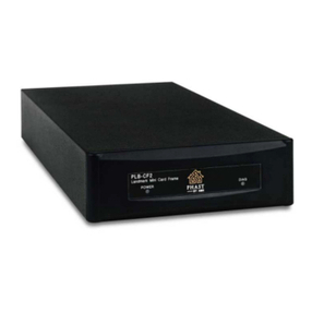
The PLB-CF10 cardframe (Figure 1) holds up to ten PHAST control cards. One is
the PLC-MCU Master Control Unit, which is essentially a computer that runs on
the Encore's PHASTLink network. The PLC-MCU runs the project code that is
stored in its 4MB onboard RAM.
Each cardframe holds ten cards (1 MCU + 9 other cards). More cardframes can be
added for special applications. The connection to a programming PC is via a high-
speed Ethernet cable.
A 15-port PHASTLink hub is built into the PHAST Cardframe. Additional
PHASTLink hub boxes can be added to accommodate any size system. Housed in
an elegant black enclosure that matches other PHAST large-chassis products,
PHAST Cardframes can be rack or shelf mounted.
PLC-MCU4 Master Control Unit Card
The PLC-MCU (Figure 2) is the master controller for the Encore system. It occupies
one slot in the first cardframe. If additional cardframes are added, they are linked
to the MCU in the first cardframe. Only one PLC-MCU is needed per system. The
MCU has one RJ-45 PHASTLan connector, which connects to a user-supplied
10Base-T Ethernet hub for connection to PHASTLan devices, such as a computer for
programming the Encore system. Each PHASTLan device requires a Cat 5 wire
home run to the Ethernet hub. A null modem cable can be used to connect a single
PC without an Ethernet hub.
Figure 1
PLB-CF10 Cardframe

Encore Quick Setup Guide Introductions3
The PLC-MCU uses non-volatile RAM for the program memory. No battery back-
up is necessary. However, as with any computer the use of a good surge suppressor
or UPS is very important. The MCU is shipped with 4 MB of nonvolatile program
memory and 4 MB of volatile memory.
The STATUS LED will blink when the PLC-MCU is online and ready for
communication. The LINK LED will blink when there is communication between
the PLC-MCU card and the PLB-CF10 cardframe.
PLC-IROUT Infrared Output Card
The PLC-IROUT (Figure 3) has four outputs for IR-controlled devices. The card will
queue commands if two outputs are already active. The card will handle up to a 10
MHz carrier. The carrier can be turned off with the software to allow control of
devices with a serial jack. The connectors are standard mini-phono connectors that
are compatible with standard Xantech emitters.
Figure 2
PLC-MCU4 Master Control
Unit Card
Figure 3
PLC-IROUT Infrared Output
Card

4Introduction Encore Quick Setup Guide
PLB-HUB2 Hub Box
THE PHAST HUB BOX (Figure 4) works like a computer network hub, distributing
the PHASTLink data bus from the Cardframe to multiple ports for large-scale,
whole-house wiring. The Hub Box accepts up to three modular, plug-in hub cards.
Housed in an elegant black enclosure that matches other PHAST large-chassis
products, PHAST Hub Boxes can be rack or shelf mounted. The PLB-HUB2 comes
with two power supplies to power touchpads or other PHASTLInk devices.
Figure 4shows a typical PLB-HUB2 configuration, containing a PLH-TPW,
PLH-VS8, and a PLH-RPT.
PLB-AS8, PLB-AS16 Audio Switch
PHAST Audio Switches distribute stereo program audio for whole-house sound
integration. Operating via the PHASTLink data bus, PHAST Audio Switches
respond to keypads, panels, or system automation—routing any input to any
output.
Each channel has automated audio pre-amp processing for volume level, balance,
bass, treble, and muting. Interactive feedback is provided for these parameters, plus
routing and signal sensing. Each input has signal sensing capability, allowing
program events to be triggered by an input signal state. Inputs can be configured as
a stereo pair, or as mono inputs. The PLB-AS16 (Figure 5) provides programmable
switching capabilities for 16 stereo outputs and 16 stereo inputs (or 32 mono
inputs).
Figure 4
PLB-HUB2 containing a
PLH-TPW, PLH-VS8, and a
PLH-RPT

Encore Quick Setup Guide Introductions5
Either 8 (PLB-AS8) or 16 (PLB-AS16) full audio zones are supported. Each output is
an audio zone, and each zone can select any input, even if that input is already
selected by another audio zone. Landmark Designer software now allows you to
automatically software-connect any audio source to inputs on ALL of the Audio
Switches in a system. This allows multiple Audio Switches to share the same
sources, increasing the number of audio zones in a system that use those sources.
Landmark software does not limit the number of Audio Switches in a system.
PHAST audio switches can be rack or shelf mounted. Matrices of up to 16 X 32 are
allowed.
PLH-VS8 Video Switch
The PLH-VS8 Video Switch (Figure 6) is the perfect partner to PHAST Audio
Switches. Each PLH-VS8 routes 8 video inputs to 8 video ouputs. It can distribute
any input to any combination of outputs, with full signal level for all destinations.
It also senses the presence of a video signal at each input, allowing a video signal to
act as a trigger event for system programming events. Encore supports up to two
PLH-VS8 Video Switches, allowing a 16x16 video matrix.
Figure 5
PLB-AS16 Audio Switch
(rear view)
Figure 6
PLH-VS8 Video Switch

6Introduction Encore Quick Setup Guide
PLB-AMP8 Audio Amplifier
The PLB-AMP8 (Figure 7) provides eight channels of amplification. The gain for
each channel can be controlled from a variety of points, including PHASTLink
devices (PHAST keypads, PHAST touchpanels), push-button controls at the back of
the amplifier, and via a PC, using the amplifier's properties page in the Landmark
software. Individual LEDs above each channel indicate selected channels. Channel
volume levels (0-99) for selected channels are displayed on LEDs at the back of the
amplifier.
PLH-RPT Hub Card
THE PHAST PLH-RPT Hub Card (Figure 8) allows the Encore system to be easily
expanded. Each PLH-RPT supports up to 15 PHASTLink wiring runs, each running
up to 1000 feet of Category 5 cable and driving up to 10 devices per port. The PLH-
RPT links to the PHAST Cardframe or other hub boxes via Hub In and Hub Out
ports. Up to three PLH-RPT hub cards can be installed in the PLB-HUB chassis box.
Figure 7
PLB-AMP8 Audio Amplifier
(rear view)
Figure 8
PLH-RPT Hub Card

Encore Quick Setup Guide Introductions7
PLH-TPW Wiring Interface and TP-A, TP-B, and TP-C Touchpads
The PHAST PLH-TPW Touchpad Wiring Interface board provides a PHASTLink
interface to PHAST NT (formerly AudioEase) TP-series touchpads, allowing them
to be used seamlessly as integral Encore system devices. Each PLH-TPW board has
connectors for up to eight TP-series touchpads, including TP-A, TP-B, and TP-C
Touchpads.
PLH-TPW firmware supports PHAST NT touchpad protocol, including buttons,
LEDs, numeric displays, and NT IR remote control functions. Up to three PLH-TPW
boards can be installed in a PLB-HUB2 box.
Computer
An Ethernet card must be installed in the computer (PC) to communicate with the
PLC-MCU card.
A computer is required to program the system with Landmark Designer software
and to download the program to the PLC-MCU Master Control Unit card in the
PLB-CF10 Cardframe. Connection from the computer to the PLC-MCU is via a
Category 5 10-BaseT null Ethernet cable with an RJ-45 connector at each end The
T568B wiring standard is used for the pin connections for the RJ-45 connector at
one end of the cable and the T568A wiring standard is used for the pin connections
at the other end of the cable.
Figure 10 shows the RJ-45 pin connections for an Ethernet null modem cable.
Figure 9
PLH-TPW Wiring Interface
and TP-A, TP-B, and TP-C
Touchpads

8Introduction Encore Quick Setup Guide
12345678
Once the program has been downloaded to the PLC-MCU card, the computer may
be disconnected from the Encore system and the program will run from the
PLC-MCU card. Allow about a minute for the program to load. If programming
changes are to be made, the computer must be reconnected to the Encore system
and the new program downloaded to the PLC-MCU.
Selecting Audio Devices
The first step in planning a new Encore installation is to determine what audio and
video devices will be used and making sure that they are IR controllable. List the
devices in the following table, including as much information as possible about
each device, including the required IR emitter type. An Encore system can control a
maximum of 36 IR-controlled devices.
Figure 10
RJ-45 pin connections for an
Ethernet null modem cable
Note
If you are connecting the
PLC-MCU to a network hub
instead of a computer, the
cable will use a direct pin-to-
pin connection (pin 1 at one
end to pin 1 at the other end,
pin 2
-to-
pin 2, etc.).

Encore Quick Setup Guide Introductions9
Manufacturer Device Type Model Information or
Part Number
IR Emitter Type and
Other Information

10 Introduction Encore Quick Setup Guide
Placing the Devices
Before mapping the wiring connections for the system, you should determine
where the various devices will be located. This may have an effect, for example, on
which IR output ports you select to control specific system devices. It will also
determine your wiring and cabling needs.
When placing devices, allow access to the connectors on the devices, as well as
following any safety guidelines described in the product documentation for those
devices, such as ventilation clearances and safe mounting procedures.
Also allow for running the necessary wires or cables to the devices in a safe and
convenient manner.
Place all of the controlled devices (CD players, tuners, TVs, VCRs, DVD players,
etc.) in the desired locations, or at least as close as possible to their final locations.
Place all of the Encore devices in the desired locations (or at least as close as
possible). It is not necessary for all Encore devices to be placed together, although it
may be more convenient to group them in a rack or entertainment center.
Double-check your device placement plan, since it is more costly and difficult to
make changes once the wiring has been made up.

Encore Quick Setup Guide Introductions11

AMX reserves the right to alter specifications without notice at any time.
brussels • dallas • los angeles • mexico city • philadelphia • shanghai • singapore • tampa • toronto • york
3000 research drive, richardson, TX 75082 USA • 469.624.8000 • 800.222.0193 • fax 469.624.7153 • technical support 800.932.6993
051-004-2438 8/01 ©2001 AMX Corporation. All rights reserved. AMX, the AMX logo, the building icon, the home icon, and the light bulb icon are all trademarks of AMX Corporation.
AMX reserves the right to alter specifications without notice at any time.
Table of contents
Other AMX Control Unit manuals