manuals.online logo
Brands
  1. Home
  2. •
  3. Brands
  4. •
  5. AMX
  6. •
  7. Control Unit
  8. •
  9. AMX HPX-AV102-RGB+A-R User manual

AMX HPX-AV102-RGB+A-R User manual

Other AMX Control Unit manuals

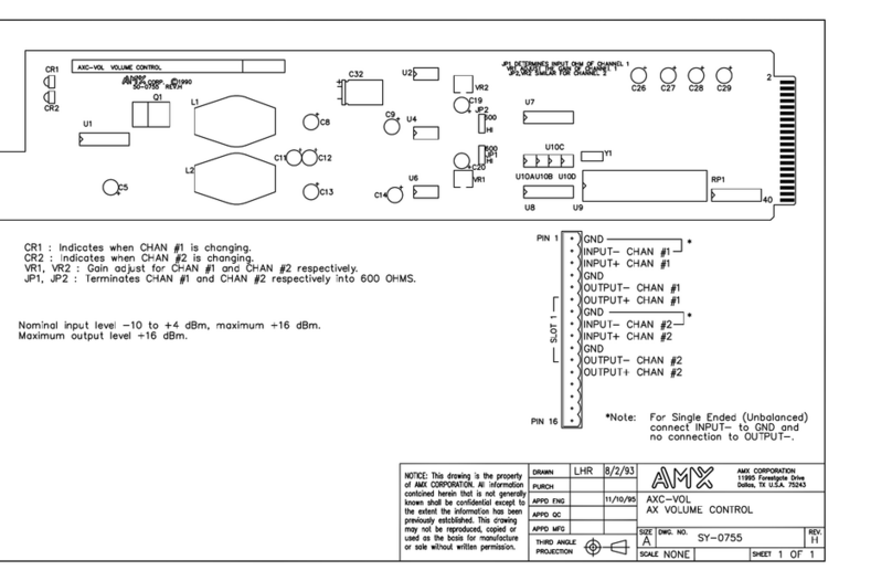
AMX AXC-VOL Guide

AMX

AMX AXC-VOL Guide

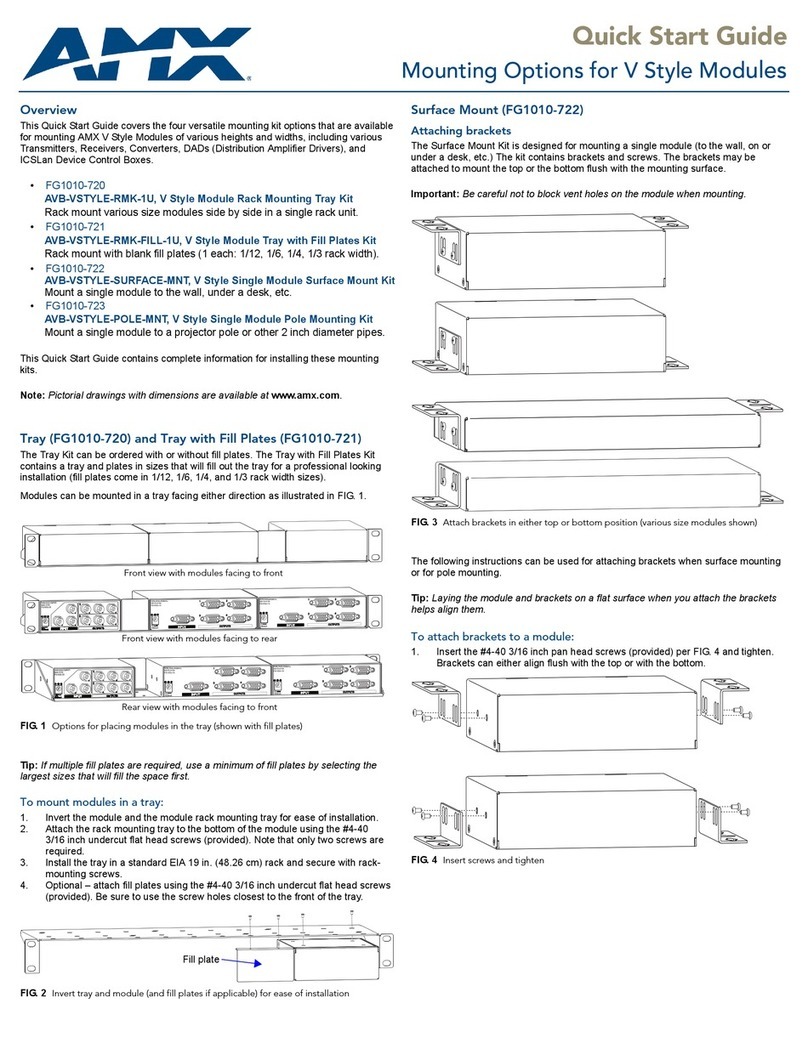
AMX FG1010-720 User manual

AMX

AMX FG1010-720 User manual

AMX AXB-PCCOM User manual

AMX

AMX AXB-PCCOM User manual

AMX HPX-AV101-DP-R User manual

AMX

AMX HPX-AV101-DP-R User manual

AMX HPX-N101-ETH-R User manual

AMX

AMX HPX-N101-ETH-R User manual

AMX CAT-5 RGBHV RX User manual

AMX

AMX CAT-5 RGBHV RX User manual

AMX RDM-DC Quick start guide

AMX

AMX RDM-DC Quick start guide

AMX CTC-1402 User manual

AMX

AMX CTC-1402 User manual

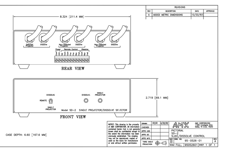
AMX SD-2 Quick start guide

AMX

AMX SD-2 Quick start guide

AMX RMX 16 User manual

AMX

AMX RMX 16 User manual

AMX HPX-AV100-RGB+A User manual

AMX

AMX HPX-AV100-RGB+A User manual

AMX RDM-ZC Quick start guide

AMX

AMX RDM-ZC Quick start guide

AMX NXS-NMS User manual

AMX

AMX NXS-NMS User manual

AMX RDM-DC Quick start guide

AMX

AMX RDM-DC Quick start guide

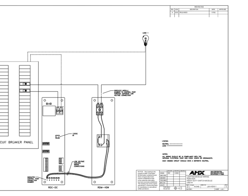
AMX RDM-HSW Quick start guide

AMX

AMX RDM-HSW Quick start guide

AMX MAX-AOM User manual

AMX

AMX MAX-AOM User manual

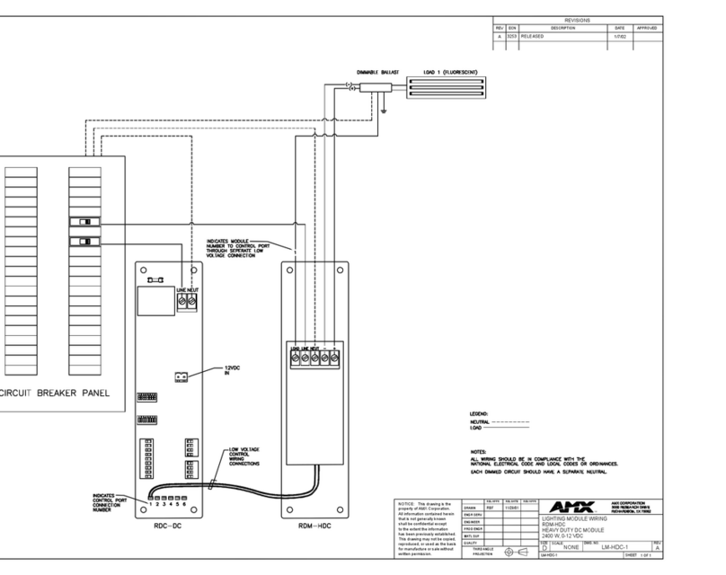
AMX RDM-HDC Manual

AMX

AMX RDM-HDC Manual

AMX HPX-N102-USB-PC User manual

AMX

AMX HPX-N102-USB-PC User manual

AMX RDA-CKM Quick start guide

AMX

AMX RDA-CKM Quick start guide

AMX 8450-03 User manual

AMX

AMX 8450-03 User manual

AMX DG RGBHV MTP User manual

AMX

AMX DG RGBHV MTP User manual

AMX AXU-MSP8 User manual

AMX

AMX AXU-MSP8 User manual

AMX MAX-AVM User manual

AMX

AMX MAX-AVM User manual

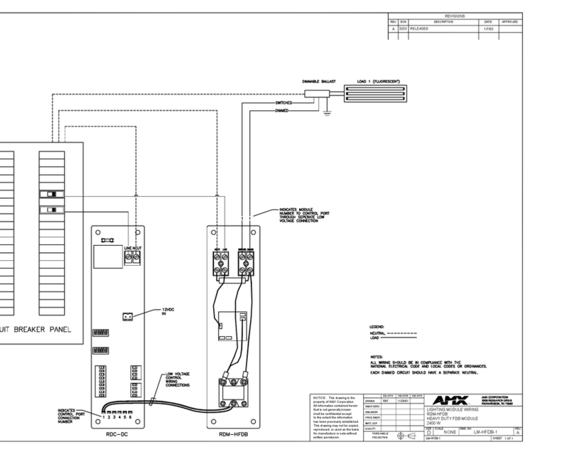
AMX RDM-HFDB Quick start guide

AMX

AMX RDM-HFDB Quick start guide

Popular Control Unit manuals by other brands

Seitz 14A80 user manual

Seitz

Seitz 14A80 user manual

Wilo RS485 Installation and operating instructions

Wilo

Wilo RS485 Installation and operating instructions

Becker CentralControl CC41 Commissioning Instruction

Becker

Becker CentralControl CC41 Commissioning Instruction

SICK CDB650 operating instructions

SICK

SICK CDB650 operating instructions

Panduit NetKey NKP5E88M Series installation instructions

Panduit

Panduit NetKey NKP5E88M Series installation instructions

MX Options Concentric Petite Fitting instructions

MX

MX Options Concentric Petite Fitting instructions

Clean Water Systems Fleck 2510 Installation & start?up guide

Clean Water Systems

Clean Water Systems Fleck 2510 Installation & start?up guide

Fairchild FSB44104A user guide

Fairchild

Fairchild FSB44104A user guide

LEGRAND Wattstopper LMIN-104 installation instructions

LEGRAND

LEGRAND Wattstopper LMIN-104 installation instructions

PMK ATT10BNCS instruction manual

PMK

PMK ATT10BNCS instruction manual

Tektronix TDS3FFT user manual

Tektronix

Tektronix TDS3FFT user manual

Woodward easYgen Technical manual

Woodward

Woodward easYgen Technical manual

Balluff BNI EIP-502-105-R015 user guide

Balluff

Balluff BNI EIP-502-105-R015 user guide

NXP Semiconductors TWR-LS1021A Getting started

NXP Semiconductors

NXP Semiconductors TWR-LS1021A Getting started

Advantech PCM-3117 Startup manual

Advantech

Advantech PCM-3117 Startup manual

Danfoss MCO 101 manual

Danfoss

Danfoss MCO 101 manual

Moons' Lin Engineering R701P user manual

Moons'

Moons' Lin Engineering R701P user manual

Aventics RV1 operating instructions

Aventics

Aventics RV1 operating instructions

manuals.online logo
manuals.online logoBrands
  • About & Mission
  • Contact us
  • Privacy Policy
  • Terms and Conditions

Copyright 2025 Manuals.Online. All Rights Reserved.

Quick Start Guide
HPX-AV102-RGB+A-R RGB-Audio Module with Retractable Cable
Overview
Hydraport Retractable Cable Modules are designed to be used in
conjunction with the HPX-600/900/1200 Connection Port base assembly, to
provide the convenience of various types of cables in a Hydraport System.
The HPX-AV102-RGB+A-R RGB-Audio Module with Retractable Cable
(FG552-31) provides a user-accessible RGB/Audio cable in a retractable
spool that mounts into the Hydraport base assembly (FIG. 1).
Installation
Warning! - Do not attempt to open the retractable cable module enclosure.
There are no serviceable parts inside the module.
Opening the module enclosure may result in an uncontrolled release of spring
forces which could cause serious injury and/or equipment damage.
Opening the module enclosure will void the product warranty.
Caution: Only use a hand-held screw driver for the mounting instructions in this
document. Over-tightening the screws can hinder performance or damage the
product.
1. For Existing HPX Installations, First Unmount the HPX Base
For new HPX installations, skip to Step 2.
For existing HPX installations, the HPX Base Assembly must be un-mounted
from the surface before the Retractable Cable Modules can be installed:
1. Cut/remove any cable ties that would restrict the removal of the HPX Base
Assembly.
2. Loosen the four mounting screws (located inside and at each end of the
HPX base assembly), in order to rotate the retaining tabs from under the
mounting surface.
Note that when the cover of the HPX base is open, only two of these
screws are visible. To access the other two mounting screws, tip the cover
over to the opposite open position (see FIG. 2).
3. Once the retaining tabs have been rotated out from under the mounting
surface, the HPX assembly can be be lifted away from the mounting
surface.
FIG. 3 provides a cutaway view of the End Cap, showing the retaining tabs
in both the loose position and the tightened (secure) position:
2. Remove the End Cap and Existing Modules
Remove the End Cap as well as existing modules (as necessary, depending on
how you want the modules arranged) from one end of the HPX base assembly.
1. Remove the (silver) pivot screw and pivot pawl assembly in the center of
the End Cap (FIG. 4).
2. Remove the six (black) sheet metal screws that secure the End Cap to the
HPX assembly (locations circled in red below).
3. Gently slide the End Cap out of the HPX base assembly.
FIG. 1 HPX-AV102-RGB+A-R RGB-Audio Module with Retractable Cable
FIG. 2 HPX Base Assembly (shown mounted) - Mounting Screws Locations
FIG. 3 HPX Base Assembly (shown mounted) - Mounting Screws Locations
FIG. 4 HPX Base Assembly (shown mounted) - Mounting/Pivot Screw Locations
For full warranty information, refer to the AMX Instruction Manual(s) associated with your Product(s).
9/13
©2013 AMX. All rights reserved. AMX and the AMX logo are registered trademarks of AMX.
AMX reserves the right to alter specifications without notice at any time.
3000 RESEARCH DRIVE, RICHARDSON, TX 75082 • 800.222.0193 • fax 469.624.7153 • technical support 800.932.6993 • www.amx.com
93-0552-31 REV: B
3. Insert the Retractable Cable Module into the HPX Base
1. Orient the module relative to the HPX base assembly so that the Module’s
faceplate is facing up, towards the mounting surface (FIG. 5).
2. Align the Mounting Notches on the module with the Mounting Rails on the
HPX base.
Note: Module faceplates are notched in a “tongue and groove" type fashion to
ensure that all modules are oriented correctly in the HPX. Note the orientation of
the notched faceplate on each module before sliding the module(s) into the HPX
assembly.
3. Slide the module into position.
4. Install any remaining modules into the HPX base.
4. Re-Install the End-Cap
Caution: Do not use a high-powered torque screw driver. Over-tightening these
screws can damage the product.
1. Align the Mounting Notches on the End Cap with the Mounting Rails on the
HPX base.
2. Slide the End Cap into the HPX base until it is fully inserted against the end
of the base assembly.
3. Secure the End Cap with the six (black) sheet metal screws (removed in
Step 2 - 2; see FIG. 4).
4. Replace the (silver) pivot screw and pivot pawl assembly (removed in Step
2 - 1, see FIG. 4) in the center of the End Cap.
5. Mount the HPX into the Mounting Surface
Caution: Do not use a high-powered torque screw driver. Over-tightening these
screws can damage the product.
Note: For detailed instructions on installing the HPX base assembly, refer to the
HPX-600/900/1200 Installation Guide (available online at www.amx.com).
1. Carefully insert the HPX base into the cutout in the mounting surface.
2. Tighten the four mounting screws (loosened in Step 1, see FIG. 3) located
inside and at each end of the HPX base assembly, to rotate the retaining
tabs into locking position under the mounting surface.
6. Terminate Fixed Cables
1. Terminate fixed cables as necessary.
Note: Use of an extension cable on either end of this cable should be
avoided to ensure optimal performance.
2. Replace any cable ties that were removed in Step 1.
Retractable (Source) RGB + Audio Connector: 3.5mm Ports
Note that the retractable cable (which connects to the Source device) features
two 3.5mm ports, one on either side of the RGB connector (FIG. 6):
• The port with the Speaker icon is the active audio port - use this port to
connect to the source device’s audio output (via the Stereo Audio Patch
Cable).
• The port with the Plug icon is inactive. It is intended to be used as a
storage port - use this port to store the Stereo Audio Patch Cable when not
in use.
Mounting Dimensions
FIG. 7 provides dimensions for the retractable cable module, when installed in
an HPX base assembly:
Additional Documentation
Refer to the Products > Architectural Connectivity catalog page on
www.amx.com (Dealer Site) for additional product documentation.
FIG. 5 Retractable Cable Module - Mounting into an HPX Base Assembly
FIG. 6 Retractable (Source) RGB + Audio Connector (Storage and Audio ports)
FIG. 7 RCM Module (installed in an HPX base) - detailed dimensions
4.65”
(11.81 cm)
End Cap
8.51”
(21.62 cm)
(of Base Assembly)