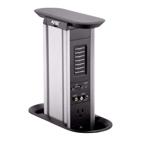
AMX AXU-MSP8 User manual

$;80063 8QL0RXQW 0LQL06RIWZLUH 3DQHO 6HULHV
DQG $;00063065
,QVWUXFWLRQ 0DQXDO
:
LUHG &RQWURO 3DQHOV

Limited Warranty and Disclaimer
AMX Corporation warrants its products to be free from defects in material and
workmanship under normal use for a period of three years from date of purchase
from AMX, with the following exceptions. Electroluminescent and LCD control
panels are warranted for a period of three years, except for the display and touch
overlay components which are warranted for a period of one year. Disk drive
mechanisms, pan/tilt heads, codecs, power supplies, modifications, MX Series
products, and KC Series products are warranted for a period of one year. Unless
otherwise specified, OEM and custom products are covered for a period of one year.
AMX software products are warranted for a period of 90 days. Batteries and
incandescent lamps are not covered.
This warranty extends to products purchased directly from AMX or an authorized
AMX dealer. Consumers should inquire from selling dealer as to the nature and
extent of the dealer’s warranty, if any.
AMX is not liable for any damages caused by its products or for the failure of its
products to perform, including any lost profits, lost savings, incidental damages, or
consequential damages. AMX is not liable for any claim made by a third party or
made by you for a third party.
This limitation of liability applies whether damages are sought, or a claim is made,
under this warranty or as a tort claim (including negligence and strict product
liability), a contract claim, or any other claim. This limitation of liability cannot be
waived or amended by any person. This limitation of liability will be effective even
if AMX or an authorized representative of AMX has been advised of the possibility
of any such damages. This limitation of liability, however, will not apply to claims
for personal injury.
Some states do not allow a limitation of how long an implied warranty lasts. Some
states do not allow the limitation or exclusion of incidental or consequential
damages for consumer products. In such states, the limitation or exclusion of the
Limited Warranty may not apply to you. This Limited Warranty gives you specific
legal rights. You may also have other rights that may vary from state to state. You
are advised to consult applicable state laws for full determination of your rights.
EXCEPT AS EXPRESSLY SET FORTH IN THIS WARRANTY, AMX MAKES NO OTHER
WARRANTIES, EXPRESSED OR IMPLIED, INCLUDING ANY IMPLIED WARRANTIES OF
MERCHANTABILITY OR FITNESS FOR A PARTICULAR PURPOSE. AMX EXPRESSLY
DISCLAIMS ALL WARRANTIES NOT STATED IN THIS LIMITED WARRANTY. ANY IMPLIED
WARRANTIES THAT MAY BE IMPOSED BY LAW ARE LIMITED TO THE TERMS OF THIS
LIMITED WARRANTY.

AXU-MSP Series and AXM-MSP32 Table of Contents i
Table of Contents
Introduction ............................................................................ 1
Overview 1
Features 2
Front Panels 2
Rear Panels 4
AXCESS Programming ........................................................... 5
Overview 5
Push Displays 5
Pushbutton LEDs 5
Bargraph Programming 6
Bargraph Modes 6
Bargraph Mode Commands 7
LED Illumination Level Commands 7
Installation .............................................................................. 9
Overview 9
Wall, Podium, and Rack Mounting Procedures 9
OLDesign Software Program ............................................... 11
Overview 11
Features 11
Specifications....................................................................... 13
Overview 13
Technical Support ................................................................ 19
Overview 19

ii Table of Contents AXU-MSP Series and AXM-MSP32

AXU-MSP Series and AXM-MSP32 Introduction 1
Introduction
Overview
The AMX UniMount Mini-SoftWire Panels (AXU-MSP) are microprocessor-
controlled pushbutton display units that can be programmed to control a wide
variety of equipment connected to an AXCESS system. The AXU-MSP series include
the AXU-MSP8, AXU-MSP16, AXU-MSP24, AXU-MSP32. The AXM-MSP32, which
contains the same pushbutton and bargraph configuration as the AXU-MSP32, can
be mounted into a 19-inch rack. This guide contains front and rear panel illustration
examples, programming instructions, installation procedures, panel specifications,
OLDesign overview, and technical support information. Figure 1shows a sample
AXU-MSP8 panel.
Figure 1
Sample AXU-MSP8 panel

2Introduction AXU-MSP Series and AXM-MSP32
Features
Each panel connects to an AMX AXCESS control system using an AXlink cable. The
panel pushbuttons perform specific operations according to the AXCESS software
and cards in your control system. Each panel comes with a custom engraved overlay
and pushbutton configuration to optimize usability. The number of pushbuttons can
vary depending on the number of operations the panel must perform. Panel features
include the following.
Features include:
• Compatible with all AXCESS control systems.
• Wide range control of multimedia presentation equipment.
• Custom engraved panels.
• Custom pushbutton functions and groupings.
• Custom LED bargraph applications.
• Installs into most standard wall box enclosures.
Front Panels
Mini-SoftWire Panel (MSP) pushbuttons can be programmed individually or in any
combination as a single device or as a group. The bargraph LEDs can also be
programmed individually or as a group. The LEDs can be used in conjunction with
any one of the pushbuttons or as an independent display indicator. Figure 2shows
the AXU-MSP16, Figure 3shows the AXU-MSP24, Figure 4shows the AXU-MSP32,
and Figure 5shows the AXM-MSP32.
Pushbutton 1
Pushbutton 5
Engraved
overlay
Pushbutton 9
Pushbutton 13
Bargraph 1
Bargraph 2
Figure 2
AXU-MSP16 panel

AXU-MSP Series and AXM-MSP32 Introduction 3
Pushbutton 1
Pushbutton 5
Engraved
overlay
Pushbutton 9
Pushbutton 13
Bargraph 1
Bargraph 2
Bargraph 3
Pushbutton 17
Pushbutton 21
Pushbutton 1
Pushbutton 5
Pushbutton 9
Pushbutton 13
Bargraph 1
Bargraph 2
Bargraph 3
Pushbutton 17
Pushbutton 21
Pushbutton 25
Pushbutton 29
Engraved
overlay
Pushbutton 1
Pushbutton 5
Pushbutton 9
Pushbutton 13
Bargraph 1
Bargraph 2
Bargraph 3
Pushbutton 17
Pushbutton 21
Pushbutton 25
Pushbutton 29
Engraved
overlay
Figure 3
AXU-MSP24 panel
Figure 4
AXU-MSP32 panel
Figure 5
AXM-MSP32 rack-mount panel

4Introduction AXU-MSP Series and AXM-MSP32
Rear Panels
The MSP rear panels contain the AXlink bus connector, AXlink LED, and the SIP
switch that is used to set the panel's device number. Figure 6shows the back panel
component configurations.
AXU-MSP16 AXU-MSP24
AXU-MSP8AXU-MSP32/AXM-MSP32
Figure 6
MSP rear panels

AXU-MSP Series and AXM-MSP32 AXCESS Programming 5
AXCESS Programming
Overview
MSP pushbuttons can be programmed individually or in any combination as single
devices or in a group arrangement. Bargraph LEDs can be programmed to interact
with panel pushbuttons. They can be programmed to work with any one of the
pushbuttons, or as independent display indicators.
Push Displays
The AXCESS software program will display the following when you press one of the
pushbuttons on your panel.
PUSH [panel device number, button number]
The pushbutton response appears in the AXCESS software program's PUSH
window. You can press the ALT and F keys on your keyboard to see what the
pushbutton does in the software program. You can also press the ALT and I keys to
insert the pushbutton in the software program and enter the pushbutton's function.
Pushbutton LEDs
Each LED in the panel's pushbuttons are assigned with feedback assignments. The
following is an example.
[Panel device number, button number of LED] = [RELAY, 1]
The LED will follow the status of device RELAY, channel, or relay number 1.
Note
Refer to the AXCESS
Language Programming
Manual for complete
programming information.

6AXCESS Programming AXU-MSP Series and AXM-MSP32
Bargraph Programming
To program LED bargraphs, commands similar to those in the following example
are included in the AXCESS software program.
DEFINE_DEVICE
VOL = 12 (* VOLUME CONTROL CARD DEVICE 12 *)
MSP = 128 (* MINI SOFTWIRE PANEL DEVICE 128 *)
DEFINE_VARIABLE
MIC_LEVEL (* VARIABLE TO HOLD CURRENT MIC *)
(* VOLUME LEVEL *)
DEFINE_START
CREATE_LEVEL VOL,2,MIC_LEVEL (* MIC_LEVEL HAS THE CURRENT LEVEL *) (* OF
CHANNEL 2 OF THE VOLUME CARD *)
DEFINE_PROGRAM
SEND_LEVEL MSP,1,MIC_LEVEL (* MIC VOLUME DISPLAYS ON FIRST BAR *)
(* GRAPH. THIS STATEMENT CAN BE *)
(* ANYWHERE IN THE PROGRAM. *)
Bargraph Modes
You can program panels using three bargraph modes; bar mode, dot mode, and
discrete mode. Bar mode (system default) will activate LEDs in a bottom-to-top
sequence. Dot mode will only activate the peak LED of the display level. Discrete
mode can be set to activate any combination of LEDs. Figure 8shows a sample
bargraph mode.
BarMode
(Default)Dot
Mode
Discrete
Mode
OnlyOne
LED
Any
Combination
ofLEDs
Figure 7
Sample AXCESS software
program
Figure 8
Sample bargraph mode

AXU-MSP Series and AXM-MSP32 AXCESS Programming 7
Bargraph Mode Commands
Figure 9lists the commands to program a bargraph.
'BMODE <Bargraph 1 - 3> <Bargraph mode 0 - 9>'
Bargraph mode options
Mode Description Mode Description
0Normal bar mode (default). 6Inverse special bar mode.
1Normal dot mode. Only the
peak LED stays on. 7Inverse special dot mode.
2Special bar mode. The first
LED is for level setting's 1 -
15.
8Individual element (discrete
mode).
3Special dot mode. The first
LED is OFF for level setting 0,
and always ON for level
setting's 1 - 15.
9Inverse individual element
(discrete mode).
4Inverse normal bar mode.
Sequences from top to
bottom.
5Inverse normal dot mode.
LED Illumination Level Commands
Figure 10 lists the commands to set the LED illumination levels on the panel's
pushbuttons and bargraphs.
'DIM <Dim mode 0 - 7>'
LED illumination level commands
Mode Description Mode Description
0100 percent duty cycle
(default). Brightest setting. 63 percent duty cycle.
150 percent duty cycle.. 71.5 percent duty cycle.
Dimmest setting.
225 percent duty cycle.
312.5 percent duty cycle.
4Inverse normal bar mode.
Sequences from top to
bottom.
54.5 duty cycle.
Figure 9
Bargraph mode options
Figure 10
LED illumination level
commands

8AXCESS Programming AXU-MSP Series and AXM-MSP32

AXU-MSP Series and AXM-MSP32 Installation 9
Installation
Overview
This section describes how to install the MSP.
Wall, Podium, and Rack Mounting Procedures
Install the wall, podium, or rack-mount MSP as follows:
1. Cut out the wall or podium according to the mounting dimensions provided in
the Specifications section of this guide. Go to step 2 if the panel will be installed
into a wall box or rack.
2. Locate and set the SIP switch on the rear side of the panel according to the SIP
switch values below. The device number is set by the total value of SIP switch
positions that are ON (down). The AXCESS software programs in your system
typically use device numbers 128 through 255 for the panels. Figure 11 shows a
SIP switch example set to device number 129 (1+128=129), and the values for
each SIP switch position.
1 2 3 4 5 6 7 8
ON
Switch 12345678
ON Value 1 2 4 8 16 32 64 128
3. Locate and connect the AXlink data and power bus to the panel as follows.
a. Strip .25 inch of insulation off each wire, and tin the ends with solder.
b. Insert each wire into the appropriate opening on the connector according to
the AXlink wiring diagram shown in Figure 12.
System
GND
AXM
AXP
PWR
GND
AXM
AXP
PWR
AXU-MSP
AXlink Connector
Black
Green
White
Red
Figure 11
SIP example and quick
reference
Note
Remove and reconnect power
when you change the panel's
device number. This will set
the new device number in
memory.
Figure 12
AXlink wiring diagram

10 Installation AXU-MSP Series and AXM-MSP32
c. Turn the captive screws clockwise to secure the wires.
d. Connect the AXlink connector to the panel.
4. Locate the green AXlink LED on the rear side of the panel. If the green LED
flashes once per second, the panel is communicating properly with the AXCESS
system. If the LED is on and not flashing, disconnect the AXlink connector and
recheck all AXlink connections. Afterwards, reconnect the AXlink connector to
the panel and verify the LED is flashing once per second.
5. Locate the slot on the front panel and gently remove the overlay from the
faceplate.
6. Place the panel in the wall, wall box, podium, or rack, and align the screw holes
with the mounting holes on the panel.
7. Fasten the panel to the wall, wall box, podium, or rack using the screws
supplied with the panel.
8. Put the engraved overlay back on the panel's bezel or rack mount faceplate.
Caution
Do not over-torque the screws
on the wires. Doing so can
bend the seating pins and
damage the connector.

AXU-MSP Series and AXM-MSP32 OLDesign Software Program 11
OLDesign Software Program
Overview
This section gives an overview of the tool to use to program the MSP.
Features
The AMX OLDesign software program is a Windows-based design tool that you can
use to create panel overlays, pushbutton names, and pushbutton operation
descriptions. The operation descriptions are used when the panel and AXCESS
operating software is programmed. OLDesign also contains an on-line help system
that provides operating instructions you can use to produce custom overlay designs
and pushbutton descriptions, and then store them on your computer. Figure 13
shows the OLDesign main window, and Figure 14 shows a sample AXU-MSP8
overlay design. Refer to the OLDesign for Windows Quick Reference Guide for
command instructions that can be used in conjunction with the OLDesign's on-line
help system.
Figure 13
OLDesign window example

12 OLDesign Software Program AXU-MSP Series and AXM-MSP32
Figure 14
Sample AXU-MSP8 overlay
design

AXU-MSP Series and AXM-MSP32 Specifications 13
Specifications
Overview
Figure 15 shows the AXU-MSP8 cutout dimensions, and Figure 16 lists the
specifications. Figure 17 shows the AXU-MSP16 cutout dimensions, and Figure 18
lists the specifications. Figure 19 shows the AXU-MSP24 cutout dimensions, and
Figure 20 lists the specifications. Figure 21 shows the AXU-MSP32 cutout
dimensions, and Figure 22 lists the specifications. Figure 23 shows the AXM-MSP32
cutout dimensions, and Figure 24 lists the specifications.
AXU-MSP8 specifications
Pushbuttons
Bargraphs
Power
Enclosure
Weight
Dimensions (HWD)
Mounting options
Options
Up to 8 black, gray, and/or white pushbuttons in a two-by-four matrix.
One-by-eight LED bargraphs.
• 12 VDC for AXlink
• 85 mA maximum per panel.
Metal with black matte finish
7.6 ounces (215.4 grams)
4.5" x 3.18" x 1.0" (114.30 mm x 8.80 mm x 25.4 mm)
• Wall mount using standard one-gang wall box
• Podium mount
• Custom logo and panels
• Color text and borders on an engraved overlay
Figure 15
AXU-MSP8 cutout dimensions
Figure 16
AXU-MSP8 specifications

14 Specifications AXU-MSP Series and AXM-MSP32
AXU-MSP16 specifications
Pushbuttons
Bargraphs
Power
Connector
Enclosure
Weight
Dimensions (HWD)
Mounting options
Options
Up to 16 black, gray, and/or white pushbuttons in a four-by-four matrix.
Two one-by-eight LED bargraphs.
• 12 VDC for AXlink
• 91 mA maximum per panel.
4-pin captive wire compression connector.
Metal with black matte finish
10.5 ounces (297.7 grams)
4.5" x 4.88" x 1.0" (114.30 mm x 124.0 mm x 25.4 mm)
• Wall mount using standard two-gang wall box
• Podium mount
• Custom logo and panels
• Color text and borders on an engraved overlay
Figure 17
AXU-MSP16 cutout
dimensions
Figure 18
AXU-MSP16 specifications

AXU-MSP Series and AXM-MSP32 Specifications 15
AXU-MSP24 specifications
Pushbuttons
Bargraphs
Power
Connector
Enclosure
Weight
Dimensions (HWD)
Mounting options
Options
Up to 24 black, gray, and/or white pushbuttons in a eight-by-four matrix.
Three one-by-eight LED bargraphs.
• 12 VDC for AXlink
• 100 mA maximum per panel.
4-pin captive wire compression connector.
Metal with black matte finish
13.1 ounces (371.3 grams)
4.5" x 6.68" x 1.0" (114.30 mm x 169.7 mm x 25.4 mm)
• Wall mount using standard three-gang wall box
• Podium mount
• Custom logo and panels
• Color text and borders on an engraved overlay
Figure 19
AXU-MSP24 mounting
dimensions
Figure 20
AXU-MSP24 specifications

16 Specifications AXU-MSP Series and AXM-MSP32
AXU-MSP32 specifications
Pushbuttons
Bargraphs
Power
Connector
Enclosure
Weight
Dimensions (HWD)
Mounting options
Options
Up to 32 black, gray, and/or white pushbuttons in a four-by-four matrix.
Three one-by-eight LED bargraphs.
• 12 VDC for AXlink
• 110 mA maximum per panel.
4-pin captive wire compression connector.
Metal with black matte finish
1.04 pounds (16.6 ounces)
4.5" x 8.48" x 1.0" (114.30 mm x 215.4 mm x 25.4 mm)
• Wall mount using standard four-gang wall box
• Podium mount
• Custom logo and panels
• Color text and borders on an engraved overlay
Figure 21
AXU-MSP32 mounting
dimensions
Figure 22
AXU-MSP32 specifications
Other manuals for AXU-MSP8
1
This manual suits for next models
3
Table of contents
Other AMX Control Unit manuals

AMX
AMX RMX 16 User manual

AMX
AMX RDM-ZC Quick start guide

AMX
AMX HPX-AV100-RGB+A User manual

AMX
AMX RDM-DC Quick start guide

AMX
AMX DG DVI MTP User manual

AMX
AMX NetLinx NXM-MHS User manual

AMX
AMX HPX-U100-BTN User manual

AMX
AMX RDM-HSW Quick start guide

AMX
AMX RDM-HFDB Assembly instructions

AMX
AMX MAX-AOM User manual
Popular Control Unit manuals by other brands

CLA-VAL
CLA-VAL 90-48 Installation operation & maintenance

turck
turck IO-LINK MASTER user manual

amc VIBRO
amc VIBRO AV ACQUISITION 4001 user manual

Emerson
Emerson KTM Series Installation and maintenance manual

emaux
emaux FLEX Series Installation and operation manual

ITRON
ITRON Centron C3A2H Technical reference guide