manuals.online logo
Brands
  1. Home
  2. •
  3. Brands
  4. •
  5. AMX
  6. •
  7. Controllers
  8. •
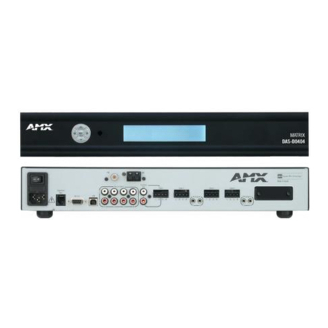
  9. AMX FG1090-170 User manual

AMX FG1090-170 User manual

Quick Start Guide
PDXL-2 Dual Power over DXLink Controller
Overview
The PDXL-2 (FG1090-170) is a Power over DXLink injector which allows for remote
powering of any two DXLink devices. The device simplifies installation by allowing the
DXLink Transmitters and Receivers to be placed anywhere even where there are no AC
power outlets—simply install a PDXL-2 in any convenient place within the 100 meter path to
provide power.
The PDXL-2 provides power for DXLink devices by “injecting” power through the twisted pair
cable. The PDXL-2 also accepts I/O control from a NetLinx controller allowing power down
capabilities to either (or both) of the connected DXLink devices to achieve power savings
when the devices are not in use.
Specifications
The following table lists the specifications for the PDXL-2:
* Cable runs with a minimum specification of ANSI/TIE/EIA 568A-5 and ratings of 250 MHz
or better may be used with DXLink equipment. However, cable run topology and
environmental influences can affect the overall successful distance capabilities of these runs.
For successful deployments up to 100 meters without consideration to outside variables,
AMX recommends the use of shielded category cable (STP) or Cat6A (or better) versions of
unshielded or shielded twisted pair (UTP/STP) for DXLink runs. For more details and helpful
cabling information, please contact your AMX representative for a copy of the white paper
titled “Cabling for Success with DXLink”.
Important Safety Information
• The PDXL-2 should be connected to DXLink devices only. Outside network
connections are not supported.
• Only qualified personnel can install or remove the PDXL-2.
• AC Power Cord Set:
* The power cord must have regulatory agency approval for the specific country in
which it is used (for example, UL, CSA, VDE, etc.)
* The power cord must be a three-conductor type (two current-carrying conductors and
one ground conductor) terminated on one end by an IEC 60320 appliance coupler
(for connection to the PDXL-2), and on the other end by a plug containing a ground
(earthing) contact.
* The power cord must be rated for a minimum of 250 VAC RMS operation, with a
minimum rated current capacity of 5 amps or a minimum wire gauge of 18 AWG
(0.75 mm2).
• A PDXL-2 installed in Australia requires power cords with a minimum wire gauge of 16
AWG (1.0 mm2).
• The PDXL-2 DATA and DATA & POWER ports are shielded RJ45 data sockets. They
CANNOT be used as Plain Old Telephone Service (POTS) telephone sockets. Only
RJ45 data connectors may be connected to these sockets.
• The AC wall socket-outlet must be near the PDXL-2 and easily accessible. You can
remove AC power from the PDXL-2 by disconnecting the AC power cord from either
the wall socket-outlet or the PDXL-2 appliance coupler.
• The PDXL-2 “DATA” and “DATA & POWER” interfaces are qualified as Safety
Extra-Low Voltage (SELV) circuits according to IEC 60950-1. These interfaces may
only be connected to SELV interfaces on other equipment.
• AMX only supports the use of our Enova DGX, Enova DVX, DXLink or Power over
DXLink solutions as the use of any other power supplies or non-compatible standard
PoE solutions may potentially damage the DXLink equipment.
WARNINGS
• The PDXL-2 should only be connected to devices compatible with this product. Using
the PDXL-2 with incompatible devices may cause damage to the device.
• Read the installation instructions before connecting the PDXL-2 to its power source.
• Follow basic electricity safety measures before connecting the PDXL-2 to its power
source.
• A voltage mismatch can cause equipment damage and may pose a fire hazard. If the
voltage indicated on the label is different from the power outlet voltage, do not connect
the PDXL-2 to this power outlet.
Mounting the Device
The PDXL-2 may be mounted on a flat surface using AVB-VSTYLE-SURFACE-MNT Surface
Mount Brackets (FG1010-722) to mount the device. See the Module Options for V Styles
Modules Quick Start Guide for mounting instructions.
• Use MPA-VRK Rack Mount Brackets (FG5968-30) for a rack mount installation.
• Use the AVB-VSTYLE-POLE-MNT Single Module Pole Mounting Kit (FG1010-723) for
a pole mount installation.
FIG. 1 PDXL-2 Dual Power over DXLink Controller
PDXL-2 Specifications
Active Power Requirements:
Power Connector (1) 100-240V, 50/60 Hz, 1.6A
Power Capabilities • Maximum Current Draw: 1.0A
• Typical Current Draw: 0.35A
Note: Power consumption depends on the device connected
to the DXLink port.
Environmental:
Temperature (Operating) 32° to 104° F (0° to 40° C)
Temperature (Storage) –4º to 158ºF (–20º to 70ºC)
Humidity (Operating) 90%, Non-condensing (maximum)
Humidity (Storage) 95%, Non-condensing (maximum)
Operating Altitude –1000 to 10,000 ft. (–304.8 to 3048 m)
DXLink:
DXLink ports (2) sets of 2 RJ-45 DXLink connectors
Transport Layer
Throughput 10.2 Gbps pass thru
PoweroverDXLinkOutput
(per output) • Pin Assignment & Polarity 4/5 (+), 7/8 (-)
• Output Power Voltage 55 VDC
• Output Power 30 Watts (guaranteed)
• Output Current 0.6 A (maximum)
Indicators:
AC Power Indicator 2 LED (1 for each DXLink Powered Output)
• Yellow (On): power is on and active
• Green (On): A remote terminal is connected
Channel Power Indicator (1) LED green
General:
Dimensions (HWD) 1 7/16” x 7” x 6 13/16” (3.63cm x 17.78cm x 17.24cm)
Weight 2.25 lbs (1.02 kg)
Front Components • AC Power Indicator
• Channel Power Indicator
• DXLink ports
Back Components (4) 3.5 mm (female) captive-wire connectors. 1 each for:
• Ground
• Relay port 1 (to be fed from I/O connection)
• Relay port 2 (to be fed from an I/O connection)
• +12V power feed
(1) Power connector
Mounting Options • Rack: MPA-VRK Rack Mounting Tray (FG5968-30)
• Surface: AVB-VSTYLE-SURFACE-MNT Surface Mount
Brackets (FG1010-722)
• Pole: AVB-VSTYLE-POLE-MNT Single Module Pole
Mounting Kit (FG1010-723)
PDXL-2 Specifications (Cont.)
Compatible AMX Products • DXLink HDMI Transmitter Module
• DXLink Multi-Format Transmitter Module
• DXLink Multi-Format Decor Style Wallplate Transmitters
(US)
• DXLink Multi-Format Wallplate Transmitters
• DXLink HDMI Receiver Module
Twisted Pair Cable Type * Cat5e, Cat6/6e, Cat6A, Cat7 of UTP, SF/UTP,
S/FTP, and F/UTP varieties
Twisted Pair Cable
Length* Up to 328 ft (100 m)
Important: DXLink twisted pair cable runs for DXLink
equipment should only be run within a common building.
Certifications • FCC Part 15 Class A
• CE EN 55022 Class A
• C-Tick CISPR 22 Class A
• UL 60950-1
• CE EN 55024
• CE EN 60950-1
• IEC 60950-1
For full warranty information, refer to the AMX Instruction Manual(s) associated with your Product(s).
12/13
©2013 AMX. All rights reserved. AMX and the AMX logo are registered trademarks of AMX.
AMX reserves the right to alter specifications without notice at any time.
3000 RESEARCH DRIVE, RICHARDSON, TX 75082 • 800.222.0193 • fax 469.624.7153 • technical support 800.932.6993 • www.amx.com
93-1090-170 REV: B
Preliminary Steps
Before placing the PDXL-2:
• Ensure that AC power is applied to the PDXL-2, using an operational ground
connection.
• Connect the incoming DXLink twisted pair connection to the Data port and connect the
twisted pair connection for the DXLink device to be powered to the Power port.
• Do not cover the device or block the airflow to the device with any foreign objects.
Keep the PDXL-2 away from excessive heat and humidity and free from vibration and
dust.
• Ensure that the cable length from the originating DXLink source to the final DXLink
destination does not exceed 328 feet (100 meters). The device is not a repeater and
does not amplify the DXLink data signal.
• The PDXL-2 does not have a power switch. Simply plug the device into an AC power
source.
Installing the PDXL-2
Perform the following steps to install the PDXL-2:
1. Connect the PDXL-2 to an AC outlet (100-240VAC) using an appropriate power cord.
2. Connect the DATA & POWER port to a DXLink Transmitter, Receiver, or Wallplate via
the appropriate twisted pair cable.
3. Use an additional twisted pair cable to connect the DATA port to a separate DXLink
Transmitter, Receiver, or Wallplate.
Note: If connecting both DATA & POWER ports to separate devices, use the provided
twisted pair cable to connect the two DATA ports together. Connecting the DATA ports
is not necessary if you are only connecting one DATA & POWER port to another
device.
4. (Optional) Connect the PDXL-2 to the I/O port on your Master so you can power off
connected devices. See Powering Off Connected Devices for details.
FIG. 2 displays an example configuration when using only one DATA & POWER port to
power a device. In this example, the RX is powered by the PDXL-2 while the TX is powered
by a local power supply, so a power line to the TX is not needed.
FIG. 3 displays an example configuration when using both DATA & POWER ports to power
two separate devices:
Pin Connections
FIG. 4 describes the PDXL-2 pin-out connections for the IN and OUT Ports on the front panel
of the device:
Relay Port Wiring
Connecting the PDXL-2 to the I/O port on your Master enables you to power off devices
connected to the PDXL-2. FIG. 5 displays the relay port on the rear panel of the PDXL-2:
Powering Off Connected Devices
The relay port on the PDXL-2 is set to ON by default.
The following diagram (FIG. 6) illustrates how the Relay Port on the PDXL-2 connects to an
I/O port on a NetLinx Master Controller:
• Note that the +12V Power pin on the PDXL-2 is a power input (unlike the relay
connectors on many other AMX products). In this case, the +12V Power (output) pin
on a NetLinx I/O Port connects directly to the +12V pin on the PDXL-2 Relay Port.
• The RELAY PORT 1 and RELAY PORT 2 pins on the PDXL-2 connect to the pins on
the NetLinx I/O port associated with the devices that will be powered off.
• Also note that a GND-to-GND connection between these connectors is not necessary.
To turn off power on a DXLink port, you must connect the relay port to an I/O port on a Master
and set the corresponding I/O channel on the Master to ON. For example, to turn off power
on DXLink port 1 (assuming the connection shown in FIG. 6):
ON [dvIO,1]
To turn on Power to DXLink port 1:
OFF [dvIO,1]
Consult the NetLinx Integrated Controllers WebConsole & Programming Guide for more
information on channels and commands.
FIG. 2 Wiring using one DATA & POWER port
FIG. 3 Wiring using both DATA & POWER ports
To RX To TX
(not used)
To RX To Wallplate
twisted pair cable
FIG. 4 PDXL-2 pin-out connections
FIG. 5 Relay Port
FIG. 6 Wiring diagram - PDXL-2 Relay port to NetLinx Master I/O port
Pins 1/2 (DATA only)
Pins 3/6 (DATA only)
Pins 4/5 (DATA + PWR)
Pins 7/8 (DATA + PWR)
= TransformerNote:
DATA
DATA
DATA
DATA
POWER (+)
POWER (-)
DATA & POWER DATA
GND = Signal Ground
RELAY PORT 2 = Input/Output
RELAY PORT 1 = Input/Output
+12V = Power input
PDXL-2 Relay Port
NetLinx Master I/O Port
PDXL-2 Relay Port
+ 12V
RELAY PORT 1
RELAY PORT 2
NetLinx I/O Port
+ 12V
I/O Port x
I/O Port x

This manual suits for next models

1

Other AMX Controllers manuals

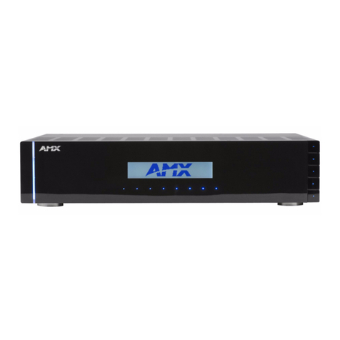
AMX NetLinx Integrated Controller NI-2100 User manual

AMX

AMX NetLinx Integrated Controller NI-2100 User manual

AMX NetLinx Integrated Controller NI-700 Operating instructions

AMX

AMX NetLinx Integrated Controller NI-700 Operating instructions

AMX NetLinx NI-3101-SIG Parts list manual

AMX

AMX NetLinx NI-3101-SIG Parts list manual

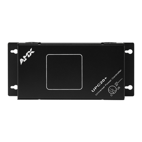
AMX UPC20 Plus User manual

AMX

AMX UPC20 Plus User manual

AMX Axcent3 pro User manual

AMX

AMX Axcent3 pro User manual

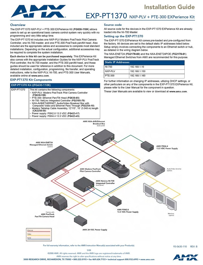
AMX EXP-PT1370 User manual

AMX

AMX EXP-PT1370 User manual

AMX NetLinx Integrated Controller NI-2100 Operating and maintenance manual

AMX

AMX NetLinx Integrated Controller NI-2100 Operating and maintenance manual

AMX AXLINK WIRING CONSIDERATIONS User manual

AMX

AMX AXLINK WIRING CONSIDERATIONS User manual

AMX NXP-PLV Parts list manual

AMX

AMX NXP-PLV Parts list manual

AMX AXC-REL8 User manual

AMX

AMX AXC-REL8 User manual

AMX AXC-232 User manual

AMX

AMX AXC-232 User manual

AMX NX-2200 User manual

AMX

AMX NX-2200 User manual

AMX Control Card RDC-DC Assembly instructions

AMX

AMX Control Card RDC-DC Assembly instructions

AMX AXB-F117 Stealth 1 User manual

AMX

AMX AXB-F117 Stealth 1 User manual

AMX Power Controller PC1 User manual

AMX

AMX Power Controller PC1 User manual

AMX AXB-CAM User manual

AMX

AMX AXB-CAM User manual

AMX PRO-DP16 DECOR PROLINK FLUSH MOUNT KEYPAD... User manual

AMX

AMX PRO-DP16 DECOR PROLINK FLUSH MOUNT KEYPAD... User manual

AMX CF2 User manual

AMX

AMX CF2 User manual

AMX AXB-TC User manual

AMX

AMX AXB-TC User manual

AMX NetLinx Integrated Controller NI-4100 User instructions

AMX

AMX NetLinx Integrated Controller NI-4100 User instructions

AMX AXB-REL8 User manual

AMX

AMX AXB-REL8 User manual

AMX NXP-PLV User manual

AMX

AMX NXP-PLV User manual

AMX NetLinx NI-2000 Operating instructions

AMX

AMX NetLinx NI-2000 Operating instructions

AMX AXB-PT15 User manual

AMX

AMX AXB-PT15 User manual

Popular Controllers manuals by other brands

Conrad 190219 instruction manual

Conrad

Conrad 190219 instruction manual

Carlisle BINKS DEVILBISS HAR-600 Service manual

Carlisle

Carlisle BINKS DEVILBISS HAR-600 Service manual

Niko 310-01100 manual

Niko

Niko 310-01100 manual

Monoprice 38166 Quick install guide

Monoprice

Monoprice 38166 Quick install guide

Vortice IRET 6 Instruction booklet

Vortice

Vortice IRET 6 Instruction booklet

Gree CE53-24/F(C) owner's manual

Gree

Gree CE53-24/F(C) owner's manual

Velleman vellight CHLSC4 installation instructions

Velleman

Velleman vellight CHLSC4 installation instructions

Alarm ADC-ACC1-17 quick start guide

Alarm

Alarm ADC-ACC1-17 quick start guide

IAI XSEL-P First step guide

IAI

IAI XSEL-P First step guide

Quest Engineering Cloud Control Base manual

Quest Engineering

Quest Engineering Cloud Control Base manual

Haven K Series quick start guide

Haven

Haven K Series quick start guide

Paragon DTC 1000 Operation & maintenance instructions

Paragon

Paragon DTC 1000 Operation & maintenance instructions

Nibe VST 11 installation instructions

Nibe

Nibe VST 11 installation instructions

Intel 6 SERIES CHIPSET -  UPDATE 01-2011 specification

Intel

Intel 6 SERIES CHIPSET - UPDATE 01-2011 specification

PVI XR10CX manual

PVI

PVI XR10CX manual

Sinclair SWC-05W user manual

Sinclair

Sinclair SWC-05W user manual

Spa-Quip SP400P user guide

Spa-Quip

Spa-Quip SP400P user guide

Aventics Marex ECS Assembly instructions

Aventics

Aventics Marex ECS Assembly instructions

manuals.online logo
manuals.online logoBrands
  • About & Mission
  • Contact us
  • Privacy Policy
  • Terms and Conditions

Copyright 2025 Manuals.Online. All Rights Reserved.