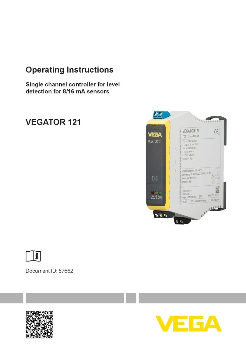
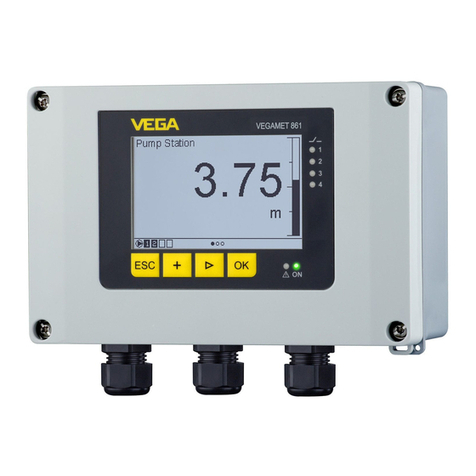
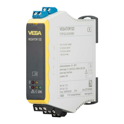
Vega VEGAMET 862 User manual

Operating Instructions
Controller in eld housing for two
continuously measuring digital or
analogue level sensors
VEGAMET 862
4 … 20 mA/HART
Document ID: 58867

2
Contents
VEGAMET 862 • 4 … 20 mA/HART
58867-EN-200312
Contents
1 About this document ............................................................................................................... 4
1.1 Function ........................................................................................................................... 4
1.2 Target group ..................................................................................................................... 4
1.3 Symbols used................................................................................................................... 4
2 For your safety ......................................................................................................................... 5
2.1 Autorisiertes Personal ...................................................................................................... 5
2.2 Appropriate use................................................................................................................ 5
2.3 Warning about incorrect use............................................................................................. 5
2.4 Allgemeine Sicherheitshinweise....................................................................................... 5
2.5 Installation und Betrieb in den USA und Kanada.............................................................. 6
2.6 Safety instructions for Ex areas........................................................................................ 6
3 Product description................................................................................................................. 7
3.1 Conguration.................................................................................................................... 7
3.2 Principle of operation........................................................................................................ 8
3.3 Adjustment....................................................................................................................... 9
3.4 Packaging, transport and storage................................................................................... 10
3.5 Accessories.................................................................................................................... 11
4 Mounting................................................................................................................................. 12
4.1 General instructions ....................................................................................................... 12
4.2 Mounting instructions ..................................................................................................... 12
5 Connecting to power supply................................................................................................. 15
5.1 Preparing the connection ............................................................................................... 15
5.2 Sensoreingang Betriebsart aktiv/passiv ......................................................................... 16
5.3 Digital input mode active/passive ................................................................................... 16
5.4 Connecting..................................................................................................................... 17
5.5 Wiring plan ..................................................................................................................... 17
5.6 Einschaltphase............................................................................................................... 19
6 Access protection.................................................................................................................. 20
6.1 Bluetooth radio interface ................................................................................................ 20
6.2 Schutz der Parametrierung............................................................................................. 20
6.3 Speicherung der Codes in myVEGA .............................................................................. 21
7 Set up with the integrated display and adjustment unit.................................................... 22
7.1 Adjustment system......................................................................................................... 22
7.2 Display ........................................................................................................................... 23
7.3 Menu overview............................................................................................................... 24
7.4 Setup steps .................................................................................................................... 24
8 Setup with smartphone/tablet (Bluetooth).......................................................................... 32
8.1 Vorbereitungen............................................................................................................... 32
8.2 Verbindung herstellen .................................................................................................... 32
8.3 Parametrierung............................................................................................................... 33
9 Setup with PC/notebook (Bluetooth)................................................................................... 34
9.1 Preparations................................................................................................................... 34
9.2 Verbindung herstellen .................................................................................................... 34
9.3 Parametrierung............................................................................................................... 35

3
Contents
VEGAMET 862 • 4 … 20 mA/HART
58867-EN-200312
10 Measured value memory/data logger .................................................................................. 36
11 Applications and functions................................................................................................... 38
11.1 Füllstandmessung im Lagertank mit Überfüllsicherung/Trockenlaufschutz .................... 38
11.2 Pumpstation mit Pumpensteuerungsfunktion................................................................. 40
11.3 Screen control................................................................................................................ 49
11.4 DurchussmessungGerinne/Wehr................................................................................. 50
12 Diagnostics and servicing .................................................................................................... 54
12.1 Maintenance .................................................................................................................. 54
12.2 Rectify faults................................................................................................................... 54
12.3 Diagnosis, fault messages ............................................................................................. 55
12.4 Softwareupdate.............................................................................................................. 57
12.5 How to proceed if a repair is necessary.......................................................................... 58
13 Dismount................................................................................................................................. 59
13.1 Dismounting steps.......................................................................................................... 59
13.2 Disposal ......................................................................................................................... 59
14 Certicatesandapprovals.................................................................................................... 60
14.1 Radio licenses................................................................................................................ 60
14.2 Approvals for Ex areas ................................................................................................... 60
14.3 Approvalsasoverllprotection....................................................................................... 60
14.4 EU conformity................................................................................................................. 60
14.5 Umweltmanagementsystem........................................................................................... 60
15 Supplement ............................................................................................................................ 61
15.1 Technical data ................................................................................................................ 61
15.2 Übersicht Anwendungen/Funktionalität.......................................................................... 64
15.3 Dimensions .................................................................................................................... 67
15.4 Gewerbliche Schutzrechte ............................................................................................. 69
15.5 License information for Open Source Software .............................................................. 69
15.6 Trademark ...................................................................................................................... 69
Redaktionsstand: 2020-03-06

4
1 About this document
VEGAMET 862 • 4 … 20 mA/HART
58867-EN-200312
1 About this document
1.1 Function
This instruction provides all the information you need for mounting,
connection and setup as well as important instructions for mainte-
nance,faultrectication,theexchangeofpartsandthesafetyofthe
user. Please read this information before putting the instrument into
operation and keep this manual accessible in the immediate vicinity
of the device.
1.2 Target group
This operating instructions manual is directed to trained personnel.
Thecontentsofthismanualmustbemadeavailabletothequalied
personnel and implemented.
1.3 Symbols used
Document ID
This symbol on the front page of this instruction refers to the Docu-
ment ID. By entering the Document ID on www.vega.com you will
reach the document download.
Information, note, tip: This symbol indicates helpful additional infor-
mation and tips for successful work.
Note: This symbol indicates notes to prevent failures, malfunctions,
damage to devices or plants.
Caution: Non-observance of the information marked with this symbol
may result in personal injury.
Warning: Non-observance of the information marked with this symbol
may result in serious or fatal personal injury.
Danger: Non-observance of the information marked with this symbol
results in serious or fatal personal injury.
Ex applications
This symbol indicates special instructions for Ex applications.
• List
The dot set in front indicates a list with no implied sequence.
1 Sequence of actions
Numbers set in front indicate successive steps in a procedure.
Battery disposal
This symbol indicates special information about the disposal of bat-
teries and accumulators.

5
2 For your safety
VEGAMET 862 • 4 … 20 mA/HART
58867-EN-200312
2 For your safety
2.1 Autorisiertes Personal
Sämtliche in dieser Dokumentation beschriebenen Handhabungen
dürfen nur durch ausgebildetes und vom Anlagenbetreiber autorisi-
ertes Fachpersonal durchgeführt werden.
Bei Arbeiten am und mit dem Gerät ist immer die erforderliche
persönliche Schutzausrüstung zu tragen.
2.2 Appropriate use
VEGAMET 862 is a universal controller for connection of two
4 … 20 mA/HART sensors.
Youcannddetailedinformationabouttheareaofapplicationin
chapter "Product description".
Operational reliability is ensured only if the instrument is properly
usedaccordingtothespecicationsintheoperatinginstructions
manual as well as possible supplementary instructions.
2.3 Warning about incorrect use
Inappropriate or incorrect use of this product can give rise to applica-
tion-specichazards,e.g.vesseloverllthroughincorrectmounting
or adjustment. Damage to property and persons or environmental
contamination can result. Also, the protective characteristics of the
instrument can be impaired.
2.4 Allgemeine Sicherheitshinweise
Das Gerät entspricht dem Stand der Technik unter Beachtung
der üblichen Vorschriften und Richtlinien. Es darf nur in technisch
einwandfreiem und betriebssicherem Zustand betrieben werden. Der
Betreiber ist für den störungsfreien Betrieb des Gerätes verant-
wortlich. Beim Einsatz in aggressiven oder korrosiven Medien, bei
denen eine Fehlfunktion des Gerätes zu einer Gefährdung führen
kann, hat sich der Betreiber durch geeignete Maßnahmen von der
korrekten Funktion des Gerätes zu überzeugen.
DerBetreiberistfernerverpichtet,währenddergesamtenEinsatz-
dauer die Übereinstimmung der erforderlichen Arbeitssicherheits-
maßnahmen mit dem aktuellen Stand der jeweils geltenden Regel-
werke festzustellen und neue Vorschriften zu beachten.
Durch den Anwender sind die Sicherheitshinweise in dieser Betrieb-
sanleitung,dielandesspezischenInstallationsstandardssowiedie
geltenden Sicherheitsbestimmungen und Unfallverhütungsvorschrif-
ten zu beachten.
EingrieüberdieinderBetriebsanleitungbeschriebenenHand-
habungen hinaus dürfen aus Sicherheits- und Gewährleistungs-
gründen nur durch vom Hersteller autorisiertes Personal vorgenom-
men werden. Eigenmächtige Umbauten oder Veränderungen sind
ausdrücklich untersagt. Aus Sicherheitsgründen darf nur das vom
Hersteller benannte Zubehör verwendet werden.

6
2 For your safety
VEGAMET 862 • 4 … 20 mA/HART
58867-EN-200312
Um Gefährdungen zu vermeiden, sind die auf dem Gerät ange-
brachten Sicherheitskennzeichen und -hinweise zu beachten.
2.5 Installation und Betrieb in den USA und
Kanada
Diese Hinweise sind ausschließlich für die USA und Kanada gültig.
Deshalb ist der folgende Text nur in englischer Sprache verfügbar.
Installations in the US shall comply with the relevant requirements of
the National Electrical Code (ANSI/NFPA 70).
Installations in Canada shall comply with the relevant requirements of
the Canadian Electrical Code.
2.6 Safety instructions for Ex areas
For Ex applications, only devices with corresponding Ex approval may
beused.ObservetheEx-specicsafetyinstructions.Thesearean
integral part of the operating instructions and are enclosed with every
device with Ex approval.

7
3 Product description
VEGAMET 862 • 4 … 20 mA/HART
58867-EN-200312
3 Product description
3.1 Conguration
The scope of delivery encompasses:
• Controller VEGAMET 862
• Mounting plate
• Screws/plugs for mounting
• Cable glands/Blind plugs (optional)
• Ground terminal for cable screening
• Informationsblatt "Dokumente und Software" mit:
– Geräte-Seriennummer
– QR-Code mit Link zum direkten Abscannen
• Information sheet "PINs and Codes" (with Bluetooth versions)
with:
– Bluetooth access code
• Informationsblatt "Access protection" (bei Bluetooth-Ausführun-
gen) mit:
– Bluetooth-Zugangscode
– Notfall-Bluetooth-Zugangscode
– Notfall-Gerätecode
Der weitere Lieferumfang besteht aus:
• Dokumentation
– Ex-spezischen"Sicherheitshinweisen" (bei Ex-Ausführungen)
– Ggf. weiteren Bescheinigungen
Note:
Optional instrument features are also described in this operating
instructions manual.The respective scope of delivery results from the
orderspecication.
This operating instructions manual applies to the following instrument
versions:
• Hardware version from 1.0.0
• Software version from 1.0.0
Scope of delivery
Scope of this operating
instructions

8
3 Product description
VEGAMET 862 • 4 … 20 mA/HART
58867-EN-200312
2
3
5
4
1
Fig. 1: VEGAMET 862
1 Display and adjustment unit
2 Housing with cable glands and connection compartment
3 Mounting plate
4 Ventilation/pressure compensation
5 Ground terminal for cable screening
Thetypelabelcontainsthemostimportantdataforidenticationand
use of the instrument:
• Instrument type
• Information about approvals
• Technical data
• Serial number of the instrument
• QR code for device documentation
• Number code for Bluetooth access
• Manufacturer information
Gehen Sie auf "www.vega.com" und geben Sie im Suchfeld die Seri-
ennummer Ihres Gerätes ein.
DortndenSiefolgendeszumGerät:
• Auftragsdaten
• Dokumentation
• Software
AlternativndenSieallesüberIhrSmartphone:
• QR-Code auf dem Typschild des Gerätes scannen oder
• Seriennummer manuell in die VEGA Tools-App eingeben (kosten-
frei verfügbar in den jeweiligen Stores)
3.2 Principle of operation
Measured value visualisation, limit value monitoring for storage tanks
andpumpingstations,owmeasurementatopenchannelsand
weirs,dierentialcalculation,stormwateroverowbasin.
Constituent parts
Type label
Dokumente und Software
Application area

9
3 Product description
VEGAMET 862 • 4 … 20 mA/HART
58867-EN-200312
The controller VEGAMET 862 is specialized in the processing and
clear reproduction of process states. A generous display for data
visualization is already integrated in the compact housing designed
forharsheldconditions.Duringoperation,thedevicefeedsthetwo
connected digital or analogue 4 … 20 mA/HART sensors.
With the VEGAMET 862 limit values can be safely monitored and
relays,suchasanoverllprotectionaccordingtoWHG,canbe
switched.The equipment includes functions for adjustment and
pump control, which allow a wide range of individual adaptations.The
VEGAMET 862 is suitable for all industrial sectors, including chemi-
cals, building materials, water and waste water.
Intheeldofwaterandwastewater,thedeviceconvinceswithfunc-
tionssuchaspumpchangeover,owmeasurementinopenchannels,
trend function, totalizer and data logger.
Das Steuergerät VEGAMET 862 kann die angeschlossenen Sen-
soren versorgen und wertet gleichzeitig deren Messsignale aus. Die
gewünschte Messgröße wird im Display angezeigt und zur weiteren
Verarbeitung zusätzlich auf den integrierten Stromausgang ausgege-
ben. Somit kann das Messsignal an eine abgesetzte Anzeige oder
übergeordnete Steuerung weitergegeben werden. Zusätzlich sind
Arbeitsrelais zur Steuerung von Pumpen oder sonstigen Aktoren
eingebaut.
3.3 Adjustment
On-site adjustment of the device is carried out via the integrated
display and adjustment unit.
The optionally integrated Bluetooth module enables in addition a wire-
less adjustment of VEGAMET 862 via standard adjustment tool:
• Smartphone/tablet (iOS or Android operating system)
• PC/notebook with Bluetooth LE or Bluetooth USB adapter (Win-
dows operating system)
Information:
Certain setting options are not possible or only possible to a limited
extent with the integrated display and adjustment unit, for example the
settingsforowmeasurementorpumpcontrol.Fortheseapplica-
tions, the use of PACTware/DTM or the VEGA Tools app is recom-
mended. An overview of the available applications and functions as
well as their adjustment options can be found in the appendix.
Funktionsprinzip
Local adjustment
Wireless adjustment

10
3 Product description
VEGAMET 862 • 4 … 20 mA/HART
58867-EN-200312
1
3
2
Fig. 2: Wireless connection to standard adjustment tools with integrated
Bluetooth LE or alternatively Bluetooth USB adapter.
1 VEGAMET 862
2 Smartphone/Tablet
3 PC/Notebook
3.4 Packaging, transport and storage
Your instrument was protected by packaging during transport. Its
capacity to handle normal loads during transport is assured by a test
based on ISO 4180.
The packaging consists of environment-friendly, recyclable card-
board. For special versions, PE foam or PE foil is also used. Dispose
of the packaging material via specialised recycling companies.
Transport must be carried out in due consideration of the notes on the
transport packaging. Nonobservance of these instructions can cause
damage to the device.
The delivery must be checked for completeness and possible transit
damage immediately at receipt. Ascertained transit damage or con-
cealed defects must be appropriately dealt with.
Up to the time of installation, the packages must be left closed and
stored according to the orientation and storage markings on the
outside.
Unless otherwise indicated, the packages must be stored only under
the following conditions:
• Not in the open
• Dry and dust free
• Not exposed to corrosive media
• Protected against solar radiation
• Avoiding mechanical shock and vibration
• Storage and transport temperature see chapter "Supplement -
Technical data - Ambient conditions"
• Relative humidity 20 … 85 %
Packaging
Transport
Transport inspection
Storage
Storage and transport
temperature

11
3 Product description
VEGAMET 862 • 4 … 20 mA/HART
58867-EN-200312
3.5 Accessories
The sun protection protects the device from direct sunlight and thus
prevents overheating of the electronics. It also improves the readabil-
ity of the display when exposed to sunlight. The sun protection can be
used for wall and pipe mounting.
Das Rohrmontage-Set dient zur optimalen und sicheren Befestigung
der Geräte bei horizontaler und vertikaler Montage an Rohren.
Sun shade
Rohrmontage-Set

12
4 Mounting
VEGAMET 862 • 4 … 20 mA/HART
58867-EN-200312
4 Mounting
4.1 General instructions
TheeldhousingoftheVEGAMET862isequallysuitableforoutdoor
or indoor installation due to its degree of protection IP66/IP67 and
Type 4X.The standard version is designed for wall mounting. A
mounting adapter for pipe mounting is available as an option.
Das Gerät ist für normale und erweiterte Umgebungsbedingungen
nach DIN/EN/IEC/ANSI/ISA/UL/CSA 61010-1 geeignet. Es kann sow-
ohl im Innen- als auch im Außenbereich eingesetzt werden.
Vermeiden Sie direkte Sonneneinstrahlung oder verwenden Sie den
optional erhältlichen Sonnenschutz.
Stellen Sie sicher, dass die in Kapitel "Technische Daten" angege-
benen Umwelt- und Umgebungsbedingungen eingehalten werden.
Protect your instrument against moisture ingress through the following
measures:
• Use the recommended connection cable (see chapter "Connect-
ing to power supply")
• Tighten the cable gland
• Mount the instrument in such a way that the cable glands point
downward
• Loop the connection cable downward in front of the cable gland
This applies mainly to outdoor installations, in areas where high
humidity is expected (e.g. through cleaning processes) and on cooled
or heated vessels.
The visible area of the front panel must be protected from knocks,
otherwise water can penetrate through breaking of the front foil. In this
case, protection against accidental contact can no longer be ensured.
Caution:
Make sure that during installation or maintenance no moisture or dirt
can get inside the instrument.
To maintain the housing protection, make sure that the housing lid is
closed during operation and locked, if necessary.
Der Druckausgleich für das Gehäuse wird über ein Druckausgleich-
selement realisiert.
Note:
Im Betrieb ist darauf zu achten, dass das Druckausgleichselement
immer frei von Ablagerungen ist. Zur Reinigung darf kein Hochdruck-
reiniger verwendet werden.
4.2 Mounting instructions
BefestigenSiedieMontageplattemitdenimLieferumfangbendli-
chen Schrauben und Dübeln gemäß nachfolgender Abbildung an der
Mounting options
Umgebungsbedingungen
Protection against mois-
ture
Druckausgleich
Wandmontage

13
4 Mounting
VEGAMET 862 • 4 … 20 mA/HART
58867-EN-200312
Wand. Achten Sie darauf, dass die Pfeile auf der Montageplatte nach
oben zeigen.
Lösen Sie die vier Schrauben im Gehäusedeckel und klappen
diesen nach links auf. Befestigen Sie das Gerät mit den beiliegenden
Schrauben (M5) auf der Montageplatte.
82 mm
(3.23")
150 mm
5.91")
82 mm
(3.23")
108 mm
(4.25")
ø13 mm
(0.51")
ø7 mm
(0.28")
Fig. 3: Montageplatte für Wandmontage VEGAMET 862
Zur Rohrmontage ist das optional bestellbare Montagezubehör
erforderlich. Dies besteht aus zwei Paar Montageklammern und vier
Montageschrauben M6 x 100.
Die Montageklammern werden gemäß nachfolgender Abbildung an
der Montageplatte und dem Rohr angeschraubt.
Lösen Sie die vier Schrauben im Gehäusedeckel und klappen
diesen nach links auf. Befestigen Sie das Gerät mit den beiliegenden
Schrauben (M5) auf der Montageplatte.
Rohrmontage

14
4 Mounting
VEGAMET 862 • 4 … 20 mA/HART
58867-EN-200312
4321 5
Fig. 4: Rohrmontage
1 VEGAMET 862
2 Montageplatte
3 4 Schrauben M6 x 100
4 Montageklammern
5 Rohr für Durchmesser 29 … 60 mm (1.14" bis 2.36")
The optional sun protection can be used to protect against direct sun-
light.The sunshade is simply mounted between the mounting plate
and the controller, this is possible for both wall and pipe mounting.
5432
16
Fig. 5: Mounting sun protection with pipe mounting
1 VEGAMET 862
2 Sun shade
3 Mounting plate
4 4 screws M6 x 100
5 Mounting brackets
6 Pipe for diameter 29 … 60 mm (1.14" to 2.36")
Mounting sun shade

15
5 Connecting to power supply
VEGAMET 862 • 4 … 20 mA/HART
58867-EN-200312
5 Connecting to power supply
5.1 Preparing the connection
Always keep in mind the following safety instructions:
• The electrical connection must only be carried out by trained,
qualiedpersonnelauthorisedbytheplantoperator.
• If overvoltage surges are expected, overvoltage arresters should
be installed.
Warning:
Only connect or disconnect in de-energized state.
DieDatenfürdieSpannungsversorgungndenSieinKapitel"Tech-
nische Daten".
Da es sich um ein Gerät der Schutzklasse I handelt, ist der Anschluss
des Schutzleiters erforderlich.
Verwenden Sie Kabel mit rundem Querschnitt. Der Kabeldurchmess-
er muss zur eingesetzten Kabelverschraubung passen, um die Dicht-
wirkung der Kabelverschraubung (IP-Schutzart) sicher zu stellen.
Die Spannungsversorgung wird mit handelsüblichem Kabel entspre-
chenddenlandesspezischenInstallationsstandardsangeschlossen.
Zum Anschließen der Sensorik kann handelsübliches zweiadriges
Kabel verwendet werden. Beim Anschluss von HART-Sensoren ist
für einen störungsfreien Betrieb zwingend eine Kabelschirmung
erforderlich.
Note:
Zu hohe Temperaturen können die Kabelisolation beschädigen.
Berücksichtigen Sie deshalb neben der Umgebungstemperatur auch
die Eigenerwärmung des Gerätes für die Temperaturbeständigkeit
des Kabels im Anschlussraum1).
When connecting HART sensors, the supplied ground terminal must
be attached to the outside of the housing.To do this, carefully remove
the pre-embossed opening (ø 6 mm) on the lower side of the device
with a suitable tool and screw in the ground terminal.
Connect the cable screening on both ends to ground potential. In the
sensor/VEGAMET 862, the shielding must be connected directly to
the internal ground terminal.The ground terminal on the outside of the
sensor housing/VEGAMET 862 must be connected to the potential
equalisation (low impedance).
If potential equalisation currents are expected, the screen connection
on the side of VEGAMET 862 must be made via a ceramic capacitor
(e. g. 1 nF, 1500 V).The low frequency potential equalisation currents
arethussuppressed,buttheprotectiveeectagainsthighfrequency
interference signals remains.
Safety instructions
Spannungsversorgung
Anschlusskabel
Cable screening and
grounding
1) BeieinerUmgebungstemperatur≥50°C(122°F)solltedasAnschlusskabel
füreinemindestens20°C(36°F)höhereUmgebungstemperaturausgelegt
sein.

16
5 Connecting to power supply
VEGAMET 862 • 4 … 20 mA/HART
58867-EN-200312
Warning:
ImAuslieferungszustandsindalleÖnungenmitStaubschutzkap-
pen versehen. Diese Kappen dienen nur zum Schutz während des
Transports und sind nicht zum Schutz während des Betriebs geeig-
net!StattdessenmüssenalleÖnungenmitKabelverschraubungen/
Blindstopfen verschlossen werden.
Kabelverschraubungen, NPT-Adapter oder Blindstopfen, die nicht im
Lieferumfang enthalten sind, müssen den geltenden Anforderungen
entsprechen, um die Umweltverträglichkeit des Gehäuses sicher zu
stellen. Bei Anwendungen im Außenbereich ist die Witterungsbestän-
digkeit des zu verwendenden Zubehörs zu berücksichtigen. Die
Kabelverschraubungen, NPT-Adapter und Blindstopfen müssen ein
metrischesGewindeM20haben,ummitdenGewindeönungender
Metallplatte im Gehäuse kompatibel zu sein.
5.2 Sensoreingang Betriebsart aktiv/passiv
Über die Auswahl der Anschlussklemmen kann zwischen aktivem
und passivem Betrieb des Sensoreingangs ausgewählt werden.
• In der aktiven Betriebsart stellt das Steuergerät die Spannungs-
versorgung für die angeschlossene Sensorik zur Verfügung. Die
Speisung und die Messwertübertragung erfolgen dabei über
die gleiche zweiadrige Leitung. Diese Betriebsart ist für den
Anschluss von Messumformern ohne separate Spannungsver-
sorgung vorgesehen (Sensoren in Zweileiterausführung).
• In der passiven Betriebsart erfolgt keine Speisung der Sensorik,
hierbei wird ausschließlich der Messwert übertragen. Dieser
Eingang ist für den Anschluss von Messumformern mit eigener,
separater Spannungsversorgung vorgesehen (Sensoren in
Vierleiterausführung). Außerdem kann das VEGAMET 862 wie ein
gewöhnliches Strommessgerät in einen vorhandenen Stromkreis
eingeschleift werden.
Note:
Bei einem VEGAMET 862 in Ex-Ausführung ist der passive Eingang
nicht vorhanden.
5.3 Digital input mode active/passive
Through the selection of the terminals, you can choose between ac-
tive and passive operation of the digital input.
• At the active input the controller provides a power supply. This
operating mode is intended for the connection of potential-free
switching contacts. An external voltage must not be supplied.
• At the passive input a voltage must be supplied via the switch-
ing contact.This input is intended for the connection of switching
contacts with their own, separate power supply.The permissible
voltagespecicationsforthiscanbefoundinthetechnicaldata.
With the application "Pump control", the digital input can be used for
pump monitoring.
Kabelverschraubun-
gen

17
5 Connecting to power supply
VEGAMET 862 • 4 … 20 mA/HART
58867-EN-200312
5.4 Connecting
The voltage supply and inputs and outputs are connected via the
spring-loaded terminals.
Information:
Solidcoresaswellasexiblecoreswithwireendsleevesare
inserteddirectlyintotheterminalopenings.Incaseofexiblecores
without end sleeves, a small screwdriver must be pressed into the
rectangular opening so that the terminal opening is then free. When
the screwdriver is pulled out, the terminals are closed again.
Youcanndfurtherinformationonthemax.wirecross-sectioninthe
technical data.
Connect the device as described in the following wiring plan.
5.5 Wiring plan
12 3
12 3
4
21 22 23
91 92
LN
+- +-+-+-
61 62 63 64 65 66 67 68 69 70 71 72 73 74 75 76 77 78 41 42 43 44 45 46 123
456
24 25 26 27 2829 30 3132
Power
65432
1S
ensor 1
Relay Output Current Output
Digital IN
Sensor 2
5
1 2 3
6 7
4
8
Fig. 6: Wiring plan VEGAMET 862
1 Voltage supply of the controller
2 Relay outputs 1 … 6
3 Current outputs 1 … 3
4 Sensor inputs 1/2 (active/passive)
5 Digital inputs 1 … 4
6 Ground terminal for protective conductor
7 Ground terminal for cable screening
8 Ground terminal for potential equalization
Connection technology
Connecting

18
5 Connecting to power supply
VEGAMET 862 • 4 … 20 mA/HART
58867-EN-200312
Detail Sensoranschluss 1
+-+-
123 123
3
1
6
5
4
2
Fig. 7: Anschluss Eingang 1 für Zweileiter-/Vierleitersensor (aktiv/passiv)
1 Aktiver Eingang mit Sensorversorgung für Zweileitersensor
2 Passiver Eingang ohne Sensorversorgung für Vierleitersensor2)
3 Zweileitersensor
4 Vierleitersensor
5 Spannungsversorgung für Vierleitersensor
6 2 mm-Buchsen zum Anschluss eines VEGACONNECT/HART-Handheld
Detail Sensoranschluss 2
3
1
5
4
2
+-+-
456 456
6
Fig. 8: Anschluss Eingang 2 für Zweileiter-/Vierleitersensor (aktiv/passiv)
1 Aktiver Eingang mit Sensorversorgung für Zweileitersensor
2 Passiver Eingang ohne Sensorversorgung für Vierleitersensor3)
3 Zweileitersensor
4 Vierleitersensor
5 Spannungsversorgung für Vierleitersensor
6 2 mm-Buchsen zum Anschluss eines VEGACONNECT/HART-Handheld
Detail, digital inputs VEGAMET 862
21 22 23 24
+- +-
25 26 27 28 29 30 31 32
1 2
+- +-
3 4
+- +-
5 6
+- +-
7 8
Fig. 9: Connection of the digital inputs
1 Digital input 1 (active)
2 Digital input 1 (passive)
3 Digital input 2 (active)
4 Digital input 2 (passive)
5 Digital input 3 (active)
6 Digital input 3 (passive)
7 Digital input 4 (active)
8 Digital input 4 (passive)
2) Passiver Eingang bei Ex-Ausführung nicht verfügbar
3) Passiver Eingang bei Ex-Ausführung nicht verfügbar

19
5 Connecting to power supply
VEGAMET 862 • 4 … 20 mA/HART
58867-EN-200312
Anschlussbelegung Digitaleingänge
21 22 23
+-
1
3
21 22 23
+-
2
43
Fig. 10: Anschlussbelegung der Digitaleingänge (aktiv/passiv)
1 Aktiver Eingang für potenzialfreien Schaltkontakt
2 Passiver Eingang für Schaltkontakt und externer Spannungsversorgung
3 Schaltkontakt
4 Externe Spannungsquelle
5.6 Einschaltphase
Nach dem Einschalten führt das Gerät zunächst einen kurzen Selbst-
test durch.
• Interne Prüfung der Elektronik
• Ausgangssignale werden auf Störung gesetzt, Hintergrund-
beleuchtung des Displays leuchtet rot
Danach werden die aktuellen Messwerte angezeigt und auf die Aus-
gänge gegeben. Die Hintergrundbeleuchtung des Displays wechselt
auf weiß.

20
6 Access protection
VEGAMET 862 • 4 … 20 mA/HART
58867-EN-200312
6 Access protection
6.1 Bluetooth radio interface
Devices with a Bluetooth radio interface are protected against un-
wanted access from outside.This means that only authorized persons
can receive measured and status values and change device settings
via this interface.
Information:
If no Bluetooth connection to the device should be possible, Bluetooth
communication can be deactivated. Access via app or DTM is thus no
longer possible.The Bluetooth function can be deactivated/activated
in the menu item "Extended functions" under "Access protection -
Bluetooth communication".
A Bluetooth access code is required to establish Bluetooth com-
munication via the adjustment tool (smartphone/tablet/notebook).
This code must be entered once when Bluetooth communication is
establishedforthersttimeintheadjustmenttool.Itisthenstoredin
the adjustment tool and does not have to be entered again.
The Bluetooth access code is individual for each device. It is printed
on the device housing and is also supplied with the device in the infor-
mation sheet "PINs and Codes". It can be changed by the user after
therstconnectionhasbeenestablished.IftheBluetoothaccess
code has not been entered correctly, a new entry can only be made
after a waiting period has elapsed.The waiting time increases with
each additional incorrect entry.
The emergency Bluetooth access code enables Bluetooth communi-
cation to be established in the event that the Bluetooth access code
is no longer known. It can't be changed. The emergency Bluetooth
access code can be found in information sheet "Access protection".
If this document is lost, the emergency Bluetooth access code can
be retrieved from your personal contact person after legitimation.
The storage and transmission of Bluetooth access codes is always
encrypted (SHA 256 algorithm).
6.2 Schutz der Parametrierung
Die Einstellungen (Parameter) des Gerätes können gegen unerwün-
schte Veränderungen geschützt werden. Im Auslieferungszustand
ist der Parameterschutz deaktiviert, es können alle Einstellungen
vorgenommen werden.
Zum Schutz der Parametrierung kann das Gerät vom Anwender mit
Hilfe eines frei wählbaren Gerätecodes gesperrt werden. Die Einstel-
lungen (Parameter) können danach nur noch ausgelesen, aber nicht
mehr geändert werden. Der Gerätecode wird ebenfalls im Bedientool
gespeichert. Er muss jedoch im Unterschied zum Bluetooth-Zugang-
scode für jedes Entsperren neu eingegeben werden. Bei Benutzung
der Bedien-App bzw. des DTM wird dann der gespeicherte Geräte-
code dem Anwender zum Entsperren vorgeschlagen.
Bluetooth access code
Emergency Bluetooth
unlock code
Gerätecode
Other manuals for VEGAMET 862
1
Table of contents
Languages:
Other Vega Controllers manuals

Vega
Vega VEGAMET 862 User manual

Vega
Vega VEGATOR 121 User manual

Vega
Vega VEGAMET 141 Installation instructions

Vega
Vega VEGATOR 122 User manual

Vega
Vega VEGAMET 861 User manual

Vega
Vega VEGAMET 141 User manual

Vega
Vega C-6124 User manual

Vega
Vega VEGAMET 624 User manual

Vega
Vega VEGATOR 132 User manual

Vega
Vega VEGAMET 342 User manual

Vega
Vega plicscom User manual

Vega
Vega VEGAMET 841 User manual

Vega
Vega VEGATOR 112 User manual

Vega
Vega VEGATOR 131 User manual

Vega
Vega VEGAMET 341 User manual

Vega
Vega VEGALOG 571 User manual

Vega
Vega VEGAMET 841 User manual

Vega
Vega VEGATOR 141 User manual

Vega
Vega VEGATOR 142 User manual

Vega
Vega VEGATOR 111 User manual