manuals.online logo
Brands
  1. Home
  2. •
  3. Brands
  4. •
  5. AMX
  6. •
  7. Receiver
  8. •
  9. AMX Mio Moderno MIO-IRRX User manual

AMX Mio Moderno MIO-IRRX User manual

Quick Start Guide
Mio Modero®IR Receiver
Overview
The Mio Modero IR (FG5797-01xx; xx indicates color selection) is a remote IR
receiver for use with NetLinx Central Controllers and operates via the AXlink bus to
remotely control devices. The Mio Modero IR is in a wall panel that fits into the US-
style single-gang enclosure and most International single-gang enclosures. The Mio
Modero IR works with AMX 38 kHz and 455 kHz IR transmitters.
Available Color Schemes
The Mio Modero device family is available in a range of colors. The IR supports these
color schemes, Black (BL), White (WH), and Beige (BG).
Wiring and Installation
Note: Before touching the device, discharge the static electricity from your body by
touching a grounded metal object.
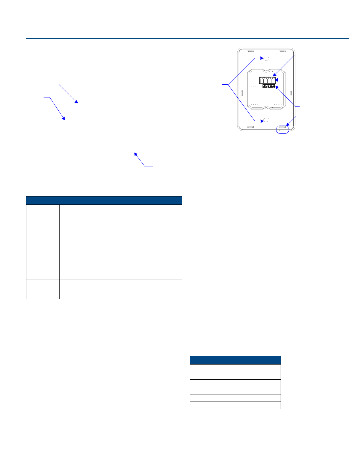
Set the receive AXlink device number before installing the Mio Modero IR. FIG. 2
illustrates the location of key components on the Mio Modero IR circuit board.
Setting the AXlink Device Number
1. If connected, disconnect the power supply.
2. Locate the 8-position Device DIP switch (FIG. 2).
3. Set the DIP switch according to the DIP switch values shown below.
The device number is set by the total value of DIP switch positions that are
ON (up).
As an example, the DIP switch in FIG. 3 defines device number 129
(1+128=129).
If you later change the device number, remove and reconnect the AXlink power
connector to enter the new device number into memory.
Preparing captive wires
You will need a wire stripper, and flat-blade screwdriver to prepare and connect the
captive wires.
1. Strip 0.25 inch (6.35 mm) of wire insulation off all wires.
2. Insert each wire into the appropriate opening on the connector according to the
wiring diagrams and connector types described in this section.
3. Turn the flat-head screws clockwise to secure the wires in the connector.
Note: Do not over-torque the screws; doing so can bend the seating pins and damage
the connector.
Wiring Guidelines
The Mio Modero IR requires 12 VDC power to operate properly. The power is supplied
by the AMX system's AXlink cable. The maximum wiring distance between the Central
Controller and the receiver is determined by power consumption, supplied voltage,
and the wire gauge used for the cable. The following table lists wire sizes and the
maximum lengths allowable between the receiver and the Central Controller. The
maximum wiring lengths are based on a minimum of 13.5 volts available at the Central
Controller's power supply. If the distance is greater than what is listed in the table,
consult the Mio Modero Device Family Instruction Manual for wiring with external
power sources.
FIG. 1 Mio Modero IR receiver
Mio Modero IR Specifications
Power: 12 vDC, 15 mA
Receive
Frequencies:
38 and 455 kHz
Range 38KHz:
• transmitter at 38Hz and at 50° horizontal angle from center
• transmitter at 38Hz and at 30° vertical angle from center
455KHz:
• transmitter at 455Hz and at 45° horizontal angle from center
• transmitter at 455Hz and at 45° vertical angle from center
Mounting: Mounts into US-style single-gang enclosures and most International
single-gang enclosures.
Dimensions
(HWD):
4.46" x 2.71" x .57" (113.28 mm x 68.83 mm x 14.48 mm)
Weight: .15 lbs (.07 kg)
Included
Accessories:
Phoenix Connector (41-5045)
Mounting Frame
Faceplate
IR Cover
FIG. 2 Location of key components on the Mio Modero IR circuit board
Switch 12345678
Value 1248163264128
FIG. 3 Example Device DIP Switch set to 129
Wiring Specifications @ 35 mA
Maximum Wiring Length
Wire Size Distance
18 AWG 3000 feet (914.40 m)
20 AWG 2121.64 feet (646.68 m)
22 AWG 1,322.75 feet (403.17 m)
24 AWG 833.80 feet (254.14 m)
AXlink
3.5 mini Phoenix
connector
Notch to pry
faceplate free
(Rear Single)
8 position mini
DIP switch
Screw
holes
PWR+
For full warranty information, refer to the AMX Instruction Manual(s) associated with your Product(s).
8/07
©2007 AMX. All rights reserved. AMX and the AMX logo are registered trademarks of AMX.
AMX reserves the right to alter specifications without notice at any time.
3000 RESEARCH DRIVE, RICHARDSON, TX 75082 • 800.222.0193 • fax 469.624.7153 • technical support 800.932.6993 • www.amx.com
93-5797 REV: G
AXlink Data and Power Connections
The Mio Modero IR uses a four-pin mini AXlink connector for power and data.
Connect the control system's AXlink connector to the AXlink connector on the rear
panel of the Mio Modero IR for data and 12 VDC power as shown in FIG. 4.
Checking AXlink Status
The AXlink LED lights to indicate AXlink power/data status as follows:
If the LED is on and not flashing, disconnect the AXlink connector and recheck all
AXlink connections. Then, reconnect the AXlink connector to the panel and verify the
LED is flashing once per second.
Mounting Procedure
AMX recommends mounting the Mio Modero IR in a standard one-gang wallbox, a
conduit box per NEC specs section 370, with a minimum internal clearance of 2-5/8"
x 1-3/4" x 1-5/8" (HWD). More installation details are available in the Mio Modero
Device Family instruction manual.
1. Use the cutout dimension for the wallbox to cutout the install surface for the
Mio Modero IR.
2. Confirm that the terminal end of the AXlink cable is disconnected, and not
receiving power.
3. If the faceplate is connected to the mounting frame, place a flathead screw-
driver in the notch at the bottom right of the Mio Modero IR, and pry the face-
plate from the mounting frame.
4. Connect the AXlink power supply. The connector passes through the center of
the mounting frame and connects to the board.
5. Place the mounting frame on the wallbox; align the screw holes with the mount-
ing holes and fasten the mounting frame to the wallbox using the screws sup-
plied.
6. Attach the faceplate to the mounting frame first at the top and swing it to the
bottom. See FIG. 6.
FIG. 4 AXlink straight-thru wiring
• 1 blink per
second
Indicates power is active and AXlink communication is working.
• 2 blinks per
second
Indicates the devices specified in the Master program do not
match the devices found.
• 3 blinks per
second
Indicates AXlink communication error.
• Full On Indicates the following conditions:
• There is no AXlink control or activity, but power is On.
• The Axcess program is not loaded.
FIG. 5 Mio Modero IR mounting dimensions
PWR +
AXP
AXM
GND -
PWR +
AXP
AXM
GND -
Mio Modero Control System
2.250
[57.2 MM]
[83.4 MM]
3.282
[50.8 MM]
2.000
FIG. 6 Attaching the faceplate to the mounting frame

This manual suits for next models

1

Other AMX Receiver manuals

AMX AVB-TX-DGX-HD15-SC Fiber User manual

AMX

AMX AVB-TX-DGX-HD15-SC Fiber User manual

AMX AXR-RF User manual

AMX

AMX AXR-RF User manual

AMX DCP-SRX User manual

AMX

AMX DCP-SRX User manual

AMX PMB-IRI User manual

AMX

AMX PMB-IRI User manual

AMX DXF-TX-MMD User manual

AMX

AMX DXF-TX-MMD User manual

AMX AutoPatch CAT-5 RGBHV RX User manual

AMX

AMX AutoPatch CAT-5 RGBHV RX User manual

AMX DXLink User manual

AMX

AMX DXLink User manual

AMX AXR-RF User manual

AMX

AMX AXR-RF User manual

AMX Sensors and Receivers IR User manual

AMX

AMX Sensors and Receivers IR User manual

AMX DXLink User manual

AMX

AMX DXLink User manual

AMX Endeleo Multi-Format Receiver UDM-RX01 User manual

AMX

AMX Endeleo Multi-Format Receiver UDM-RX01 User manual

AMX AXC-RCVI User manual

AMX

AMX AXC-RCVI User manual

AMX AXD-IR Plus User manual

AMX

AMX AXD-IR Plus User manual

AMX Endeleo Multi-Format Receiver UDM-RX02 User manual

AMX

AMX Endeleo Multi-Format Receiver UDM-RX02 User manual

AMX PMB-RF User manual

AMX

AMX PMB-RF User manual

AMX Viewpoint AXR-RF User manual

AMX

AMX Viewpoint AXR-RF User manual

AMX AXU-IR User manual

AMX

AMX AXU-IR User manual

AMX AXD-IR Plus User manual

AMX

AMX AXD-IR Plus User manual

AMX MX8 User manual

AMX

AMX MX8 User manual

AMX Viewpoint AXR-RF User manual

AMX

AMX Viewpoint AXR-RF User manual

AMX Endeleo Multi-Format Receiver UDM-RX02 Parts list manual

AMX

AMX Endeleo Multi-Format Receiver UDM-RX02 Parts list manual

AMX UDM-RX02N User manual

AMX

AMX UDM-RX02N User manual

AMX AXR-IRSM Plus User manual

AMX

AMX AXR-IRSM Plus User manual

AMX AXR-IRSM Plus User manual

AMX

AMX AXR-IRSM Plus User manual

Popular Receiver manuals by other brands

Sansui SQ-115 instruction manual

Sansui

Sansui SQ-115 instruction manual

Aiwa CR-SP40 operating instructions

Aiwa

Aiwa CR-SP40 operating instructions

RF-Link WHD-5001 user manual

RF-Link

RF-Link WHD-5001 user manual

Inverto 3524 user manual

Inverto

Inverto 3524 user manual

Sony STR-ZA810ES operating instructions

Sony

Sony STR-ZA810ES operating instructions

Philips Matchline DSR5600 user guide

Philips

Philips Matchline DSR5600 user guide

Vermes MHA-K-230/48 Quick reference guide

Vermes

Vermes MHA-K-230/48 Quick reference guide

Octagon SF 1028P HD - Noblence user manual

Octagon

Octagon SF 1028P HD - Noblence user manual

Sony BKM-500 operating instructions

Sony

Sony BKM-500 operating instructions

Thrane&Thrane SAILOR 6390 user manual

Thrane&Thrane

Thrane&Thrane SAILOR 6390 user manual

Austdac SILBUS-RX4A user manual

Austdac

Austdac SILBUS-RX4A user manual

Huawei OptiX RTN 320 Quick installation guide

Huawei

Huawei OptiX RTN 320 Quick installation guide

Veris Multimedia Station E-Z installation guide

Veris

Veris Multimedia Station E-Z installation guide

FrSky DFT instruction manual

FrSky

FrSky DFT instruction manual

Denon AVR-2113CI Getting started guide

Denon

Denon AVR-2113CI Getting started guide

Grace Industries MS900 Series User information

Grace Industries

Grace Industries MS900 Series User information

BSRF ACH-642 instructions

BSRF

BSRF ACH-642 instructions

Sony HCD-H170 Service manual

Sony

Sony HCD-H170 Service manual

manuals.online logo
manuals.online logoBrands
  • About & Mission
  • Contact us
  • Privacy Policy
  • Terms and Conditions

Copyright 2025 Manuals.Online. All Rights Reserved.