VER. 003_20.05.2011
4-CHANNEL RADIO TRANSMITTER RNP-01
MANUAL INSTRUCTION
APPEARANCE
TECHNICAL DATA
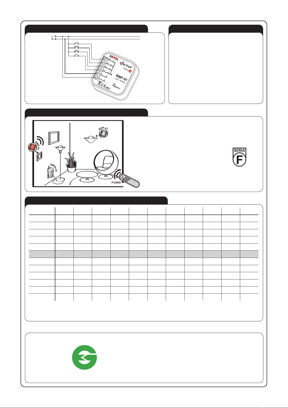
RNP-01
Input (supply) terminals: L, N
Input rated voltage: 230 V AC
Input voltage tolerance: -15 ÷ +10 %
Nominal frequency: 50 / 60 Hz
Nominal power consumption: 0,22 W
Release terminals: IN1, IN2, IN3, IN4
Number of channels: 4
Transmission: radio 868,32 MHz
Transmission way: unidirectional
Coding: addressing transmission
Range: up to 200 m in the open area
Optic signalling of transmission: LED red diode
Ambient temperature range: -10 ÷ +55 oC
Number of terminal clamps: 6
Section of connecting cables: up to 2,5 mm2
Operating position: free
Casing mounting: installation cable box Ø 60 mm
Casing protection degree: IP20 (EN 60529)
Protection level: II
Overvoltage category: II
Pollution degree: 2
Surge voltage: 1 kV (EN 61000-4-5)
Dimensions: 47,5 x 47,5 x 20 mm
Weight: 0,031 kg
Reference standard: ETSI EN 300 220-1, ETSI EN 300 220-2,
EN 60950, EN 61000
The device is designed for
single-phase installation and
must be installed in accordance
with standards valid in a particu-
lar country. The device should
be connected according to the
details included in this operat-
ing manual. Installation, connection and control
should be carried out by a qualied electrician
staff, who act in accordance with the service
manual and the device functions. Disassembling
of the device is equal with a loss of guarantee and
can cause electric shock. Before installation make
sure the connection cables are not under voltage.
The cruciform head screwdriver 3,5 mm should
be used to instal the device. Improper transport,
storage, and use of the device inuence its wrong
functioning. It is not advisable to instal the device
in the following cases: if any device part is miss-
ing or the device is damaged or deformed. In case
of improper functioning of the device contact the
producer.
CAUTION!
FEATURES
DESCRIPTION
● radio transmitter mounted in Ø 60 mm
junction box,
● remote control of EXTA FREE system
receivers,
● possibility of connection to a traditional
household switch,
● low power consumption, adapted to
constant operation,
● possibility of independent control of
four receivers,
● wide range of operation (up to 200 m),
● possibility of simultaneous switching
on/switching off any number of EXTA
FREE system receivers,
● possibility of increasing operation ran-
ge by means of RTN-01 retransmitter.
Radio transmitter RNP-01 realises
remote control function of devices.
It is mounted in a junction box and under
the existing switch (monostable push-
buttons). This solution is very useful and
results in easy installation of EXTA FREE
system without interference in existing
wiring system. There is a possibility of us-
ing electroinstallation equipment of any
manufacturer (no design limit).
The symbol means selective
collecting of electrical and electronic
equipment. It is forbidden to put
the used equipment together
with other waste.
Optic signalling of receiver’s operation
Input (supply) terminals (L, N)
Release terminals (IN1, IN2, IN3, IN4)