5
Rev B
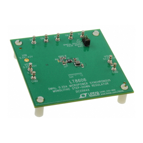
DEMO MANUAL DC1366B
OPERATION
Introduction
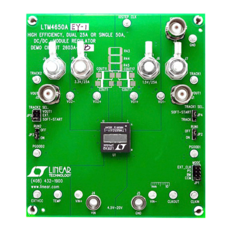
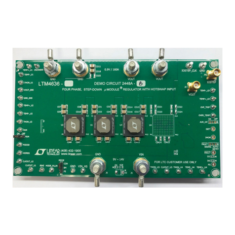
The DC1366B demonstrates the features and capabilities
of the LTC4266, a quad controller for IEEE802.3at Power
SourcingEquipment(PSE).TheDC1366B providesaquick
and simple, fully compliant PSE solution requiring only
a VEE supply when used in conjunction with the DC590
USB-to-I2C interface board.
Supply Voltages
The IEEE802.3at standard requires the port output volt-
age of a type 2 PSE to be in the range of 50V to 57V. The
positive side is RTN and the negative side is VEE. The VEE
supply voltage should be in this range for the sake of
compliance; however, the LTC4266 is capable of operat-
ing with VEE down to 30V, the max undervoltage lockout
(UVLO) threshold.
Make sure to choose a VEE supply with enough power to
sustain all four ports at maximum load; if the total load is
too great for the power supply its voltage may drop below
the UVLO threshold, resetting the LTC4266 and shutting
off all the ports. The worst case is when all four PDs are
class 4: each class 4 PD may draw up to 600mA, totaling
2.4A. Therefore a VEE supply rated for at least 2.6A is
recommended.
The VDD supply should nominally be 3.3V but the LTC4266
is capable of operating over the range of 3.0V to 4.3V.
(The UVLO threshold for the VDD supply is typically 2.2V.)
The LTC4266 chip typically draws only 1.1mA from the
VDD supply; however, LEDs and other components on
the DC1366B board also draw current from VDD, so the
total load is typically 9mA to 26mA at 3.3V depending on
which LEDs are lit.
VDD to DGND Configurations
The DC1366B, LTC4266 VDD supply can be configured in
one of two ways. The default DC1366B configuration ties
the LTC4266 VDD pin to the AGND pin through a 0 Ohm
resistor R10. The DGND pin is at –3.3V below the AGND
pin. The DC1366B can also be configured for a +3.3V at
VDD relative to AGND by removing R10 and installing a
0Ω resistor at R9. This ties the LTC4266 DGND pin and
AGND pin.
Modes of Operation
The LTC4266 has four modes of operation:
nShutdown: Ports are shutdown, detection and clas-
sification cycles are disabled.
nManual:Theport doesnot advance automaticallyfrom
detection to classification, to power on. It waits for
instructionsfrom ahost controller via the I2Cinterface.
nSemiauto: The port automatically advances to clas-
sification after detecting a PD, but does not turn on
power to the PD until told to do so by from a host
controller via the I2C interface.
nAUTOPin High:The LTC4266 operatesautonomously.
AUTO Pin
The AUTO pin determines several aspects of the LTC4266
initial behavior. AUTO is sensed by the LTC4266 at power
up and after a reset.
If the AUTO pin is high then:
nAll ports come up in AUTO pin high mode. Any valid
PD will be turned on without software intervention.
nThe current-sense resistors are assumed to be 0.25Ω
(which they are on the DC1366B).
nHigh power is enabled. After the LTC4266 classifies a
PDit applies powerand automaticallysets ICUT and ILIM
appropriately for the class. With high-power enabled a
class 4 PD will be able to draw up to 600mA without
being cut off.
If the AUTO pin is low then:
nAll ports come up in shutdown mode. A host controller
must take action in order to power up any PDs.
nThe current-sense resistors are assumed to be 0.50Ω;
a host controller must change this to 0.25Ω for correct
operation of the DC1366B.
nHigh power is disabled and is enabled by a host con-
troller.
Downloaded from Arrow.com.Downloaded from Arrow.com.Downloaded from Arrow.com.Downloaded from Arrow.com.Downloaded from Arrow.com.
