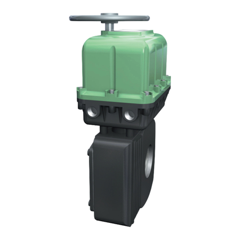
Dresser Surepowr Sure 150 User manual

Surepowr Series
Sure 150
Installation Manual
Table of Contents
Intended of Usage ................................................................... 2
Actuator Range of Application........................................... 2
1. Actuator Marking.....................................................3
2. Special Conditions for Safe Use
(ATEX)/Conditions of Certication (IECEx) ............3
3. Ratings ......................................................................3
4. Safety ........................................................................4
Safety First!........................................................................................... 4
Warnings and Notices...................................................................... 4
Joint Handling .................................................................................... 4
Fasteners............................................................................................... 5
Seals........................................................................................................ 5
Cable Glands ....................................................................................... 5
Grounding and Bonding ................................................................ 5
Spring Housing................................................................................... 5
Enclosure Surface Temperature................................................... 5
5. Installation................................................................6
Dimensional Information............................................................... 6
Dimensional Information............................................................... 7
Cover Removal and Assembly...................................................... 8
Mounting.............................................................................................. 8
Horizontal Mounting .............................................................. 8
Conduit Locations and Thread Sizes.......................................... 9
Cable Glands ....................................................................................... 9
Grounding and Bonding ................................................................ 9
Wiring..................................................................................................... 9
Wiring Diagrams....................................................................... 9
Mechanical Stop Settings ............................................................11
Limit Switch Settings .....................................................................11
Switch adjustments for clockwise spring fail
operation (viewed from the top of the actuator)......11
Switch adjustments for counter-clockwise spring fail
operation (viewed from the top of the actuator)......11
Limit Switch Settings (Optional Oering) .............................12
Installation.................................................................................12
6. Operation............................................................... 13
Thermal Overload ...........................................................................13
Duty Cycle ..........................................................................................13
Optional Manual Override...........................................................13
7. Maintenance.......................................................... 13
Mounting Fasteners .......................................................................13
Enclosure Cover Screws................................................................13
Seals and Cable Glands.................................................................14
8. Storage................................................................... 14
RCS Actuators

2
WARNING
PPE
Approved Personal Protection
Equipment for the site must
be worn.
This manual gives instructions for storing, installing,
operating and servicing the RCS Surepowr* Series
Sure 150 electrical mechanical actuator. Refer all
questions not covered in this manual to:
Dresser Natural Gas Solutions
16240 Port Northwest Drive Houston, TX 77041
Tel. 832-590-2306 Fax. 713-849-2879
Be sure to include the model and serial number located
on the nameplate of your Sure 150 actuator in all
communications and parts orders. The nameplate is
located on the bottom portion of the spring housing.
Follow local / regional electrical safety laws and
regulations.
Intended of Usage
Make Special Note of the following information
regarding intended use for this equipment.
Consult the following documents for intended
use standards:
a) EN(IEC)60079-14 standard
(Explosive Atmospheres – Part 14: Electrical
Installations Design, Selection and Erection)
b) EN(IEC)60079-17 standard
(Explosive Atmospheres – Part 17: Electrical
Installations Inspection and Maintenance)
c) Any laws, decrees, standards, procedures
or other documents related to the area
in which the actuator shall be installed
Dresser Natural Gas Solutions (NGS) cannot be held
responsible if these standards are disregarded.
Check the compatibility of the actuator’s nameplate
markings with the classication of the installation
area’s environment and its ambient and admissible
surface temperatures.
Only qualied, certied and properly trained personnel
should conduct actuator installation and maintenance.
Actuator Range of Application
For use in EU countries, IEC participating countries
and any others that accept ATEX/ IECEx certication
This device is designed to meet CE Machinery
directive 2004/42/EC (EN 12100:2010, EN 14121-1:2007)
and Electromagnetic Compatibility (EMC) Directive
2004/108/EC (EN 61000-6-4: 2007, EN 61000-6-2: 2005).
For use in North American“Class, Division”
Classied Areas:
This device is designed for installation in Class I, Division
1 Groups C and D and Class II, Division 1 Groups E, F and
G rated environments within an operating temperature
range of -40°C to +65°C.

3
1. Actuator Marking
ATEX Explosion
Proof Enclosure
“d”/Dust
Protection by
Enclosure“Tb”
North American
Class/Div.
Europe CE
marking
Name and
Address of
Manufacturer
Dresser NGS
16240 Port
Northwest Drive
Houston, TX
77041
Dresser NGS
16240 Port
Northwest Drive
Houston, TX
77041
Actuator Type Electrical
Mechanical
Surepowr Series
Electrical
Mechanical
Surepowr Series
Certicate
Number
SIRA 15 ATEX
1058x/IECEx SIR
15,0034X
Master Contract:
157578
Specic Marking εx II 2 GD;
-NN°C > Ta >
65°C
No. of notied
audit body
Sira 15 ATEX
1058x
CSA
Gas Marking Ex d IIB T5 Gb Class I, Div I,
Grp. C,D
Dust Marking Ex tb IIIC T85°C
DbAmbient
Temperature
Class II, Div I
Grp E, F, G
Ambient
Temperature
-20°C (-4°F) to
+65°C (150°F)
-40°C (-40°F) to
+65°C (150°F)
Note Any temperature
below -20°C
(-4°F) (over
pressure
test required)
CE Marking Machinery
Directive;
2004/42/EC
(EN 12100:2010,
EN 14121-1:2007)
NA
CE Marking EMC Directive;
2004/108/EC
(EN 61000-6-
4:2007,
EN 61000-6-
2:2005)
NA
NOTICE:
The Actuator Marking Plate shall not be damaged,
covered up or painted over.
Actuator identication and specications must remain visible.
2. Special Conditions for Safe Use
(ATEX)/Conditions of Certication
(IECEx)
1. The equipment uses M10x1.5 stainless steel special
fasteners of grade A4-80 and yield strength 600 MPa. If
fasteners are replaced, they shall be replaced with the
equivalent size and grade.
2. Some external parts of the equipment are non-
conducting and may generate an ignition-capable
level of electrostatic charge under certain extreme
conditions. Ensure that the equipment is not installed
in a location where it may be subjected to external
conditions (such as high-pressure steam) that might
cause build-up of electrostatic charges on non-
conducting surfaces. Additionally, the equipment
should be cleaned with a damp cloth.
3. The equipment contains amepaths that are other
than the relevant minimum or maximum dimensions
as specied in IEC 60079-1:2012 Table 1. The essential
parameters are:
Flamepath Type
Min.
design
length
Max.
design
gap
Cover to
Shaft
Cylindrical 25.89 mm 0.10 mm
Cover to
Gear Case
Flange 23.39 mm .0762 mm
Gear Case
to Spring
Housing
Flange 23.37 mm .0762 mm
Shaft to
Yoke
Spigot 19.40 mm .08 mm
Yoke to
Spring
Housing
Rabbet 26.14 mm .0762 mm
(ange)
.1mm
(cylinder)
3. Ratings
Power [kW] Sure 150
Nominal Supply Voltage
[V]
115/120;
220/230 (VAC)
(50/60 Hz)
Nominal Current [A] 1.9
Nominal Torque [Nm] 136
Duty Cycle (max
frequency)
25
Temperature See Above
Protection Class d
Weight 120 lb (55kg)
The actuator has been tested and certied for Ingress
Protection IP 66/67 and type 4, 4X & 6.

4
4. Safety
Safety First!
In the maintenance and operation of mechanical
equipment, safety must be considered at all times.
Through the use of the proper clothes, tools, and
methods of handling, serious accidents can be prevented.
A number of safety precautions are listed throughout
this manual. Study them carefully and follow them, and
insist that those working for and with you do the same.
Remember, an accident is usually caused by carelessness,
neglect, or oversight.
Warnings and Notices
Pictograms are used throughout this manual to denote
important or dangerous situations. If warnings are not
respected, dangerous situations may result that may
cause serious personal injury or death. Examples of
the pictograms throughout this manual:
WARNING
GROUNDING LUG:
Unit must be grounded
with minimum size
10 AWG wire.
WARNING
Indicates a hazardous situation that, if not avoided, could result in
death or serious injury.
WARNING
ELECTRICAL SHOCK WARNING:
Indicates a risk of death or serious
injury due to electrical shock if
safety measures are not adhered
to.
NOTICE:
Indicates practices not related to personal injury,
but addresses important information regarding the installation,
operation or maintenance of the unit.
CAUTION:
Indicates a potentially hazardous situation that, if not avoided,
can result in minor to moderate injury, or serious damage
to the product. The situation described in the CAUTION may,
if not avoided, lead to serious results. Important safety measures
are described in CAUTION (as well as WARNING), so be sure
to observe them.
Observe these and all other warnings at all times during
installation, operation and maintenance of this product:
WARNING
EXPLOSION HAZARD
Death or serious injury
could result.
Do not open unless power to
actuator has been disconnected.
WARNING
EXPLOSION HAZARD
Death or serious injury
could result.
Do not open if an explosive
atmosphere may be present.
WARNING
ELECTRICAL SHOCK WARNING:
Indicates a risk of death or serious
injury due to electrical shock if
safety measures are
not adhered to.
WARNING
HIGH ENERGY HAZARD
Death or serious injury
could result.
Do not attempt to repair actuator
unless properly trained in specic
repair methods for this device.
Joint Handling
WARNING
LIFTING HAZARD
May result in injury.
See safety manual for lifting
instructions
WARNING
EXPLOSION HAZARD
Death or serious injury
could result.
Do not open unless
power to actuator has been
disconnected.
WARNING
EXPLOSION HAZARD
Death or serious injury
could result.
Do not open if an
explosive atmosphere
may be present.

5
Do not open actuator cover if there is risk of an
explosive environment. Care must be taken with the
joint surface when handling, installing or storing to
preserve the integrity of the explosion-proof joint. See
joint handling instructions under the Installation section
of this manual. Failure to observe these instructions may
compromise the enclosure protection rating.
Fasteners
Both Metric and Imperial fasteners used, use applicable
tools. The enclosure cover bolts and the hard stop
assembly are metric threads and the rest of the others are
imperial threads.
All fasteners must be intact and properly tightened.
Enclosure cover screws, mounting fasteners and cable
glands must be tightened to specied torque values.
Failure to maintain specied torque for cover screws and
cable glands may compromise the enclosure protection
rating. Failure to maintain specied torque for mounting
fasteners may compromise actuator operation. See
Installation and Maintenance sections of this manual
for specied fastener and torque requirements, as
well as safety and maintenance information.
WARNING
EXPLOSION HAZARD
Death or serious injury
could result.
Maintain cover screw and
cable gland fastener torque
specications to ensure enclosure
protection.
Seals
All seals must be routinely checked to ensure that
they are in good condition, properly sealed and
replaced as needed. Failure to do so may compromise
the enclosure protection rating. See Installation and
Maintenance sections for instructions.
WARNING
EXPLOSION HAZARD
Death or serious injury
could result.
Maintain all seals to ensure
enclosure protection.
Cable Glands
Cable glands must be installed and maintained
and properly torqued according to the Installation
and Maintenance specications. Failure to do so
may compromise the enclosure protection rating.
See Installation and Maintenance sections for
instructions.
WARNING
EXPLOSION HAZARD
Death or serious injury
could result.
Maintain cable gland torque
specications to ensure enclosure
protection.
Grounding and Bonding
Failure to properly ground or bond the device may
result in death or serious injury due to explosive hazards.
See Bonding and Grounding under the Installation
section of this manual for proper specications.
WARNING
EXPLOSION HAZARD
Death or serious injury
could result.
Ensure device is
properly grounded to
avoid explosion hazard.
Spring Housing
Caution:
Loaded spring inside actuator.
Do not attempt to repair actuator below top gear plate,
unless properly trained on repair methods.
Enclosure Surface Temperature
Enclosure surface temperature may be higher due to
operation. This could result in burns to the operator’s
hand if touched while the enclosure is hot. Please
allow the enclosure to cool to the specied ambient
temperature range before touching the enclosure
for handling.
WARNING
BURN HAZARD
Hot surface inside.
Allow to cool before servicing.

6
5. Installation
WARNING
HIGH ENERGY HAZARD –
LOADED SPRING
Death or serious injury
could result.
Do not attempt to repair actuator
unless properly trained in specic
repair methods for this device.
Notice:
SurePowr actuators can be supplied for clockwise or
counter-clockwise spring-driven rotation
(viewed from the top of the actuator).
The spring drive rotation is noted on the
actuator name tag and wiring diagram.
Ensure that the actuator has been supplied with the
proper spring drive operation for the application prior
to installation on the driven device.
Dimensional Information
Figure 1

7
Dimensional Information
Figure 2

8
Cover Removal and Assembly
Do not open the actuator cover if there is risk of an
explosive environment.
WARNING
EXPLOSION HAZARD –
REMOVE POWER
Death or serious injury
could result.
Do not open unless power to
actuator has been disconnected.
WARNING
EXPLOSIVE ATMOSPHERE
HAZARD
Death or serious injury
could result.
Do not open if an explosive
atmosphere may be present.
Do not store or set the actuator cover with the ange
surface down. To preserve the explosion-proof integrity
of the joint, care must be taken not to damage, scu or
score the ange joint surfaces and associated parts (cable
glands, joints, etc.). Take care not to damage the cover
joint when replacing the cover onto the actuator housing.
Ensure that the joint is clean and free of debris or
damage and ensure that the O-ring is intact and in place
before replacing the cover onto the actuator housing.
The explosion-proof joint may be lubricated with an
appropriate, non-corrosive, non-hardening grease, such
as Vaseline.
When replacing the actuator cover, ensure the eight
cover screws are tightened to specied torque value
and that all screws are intact. Failure to maintain specied
screw torque may compromise the enclosure protection
rating.
Under normal operation, the capacitor will discharge
prior to the removal of the cover.
Enclosure cover screw specications:
Exd or EEx d versions:
8, 10mm x 1.5 x 35 mm,
A4-80 Stainless steel,
apply anti-freeze compound;
torque to 32-33 ft.-lbs. (43-44 N.m)
WARNING
EXPLOSION HAZARD
Death or serious injury
could result.
Maintain cover screw torque
specications to avoid hazard.
Mounting
The actuator is shipped in the fail safe position. Ensure
that the driven device is oriented to its desired fail
position prior to installation or any maintenance work
of the actuator.
Care should be taken to maintain proper alignment
between the actuator and the device shaft. The actuator
should install on the shaft without binding. The mounting
face should be centered on the bracket without binding
or side load.
Mount the actuator to the device. Ensure the actuator
is centered properly with the device shaft, and then
tighten all screws and nuts to the mounting fastener
spec. below.
Mounting Fastener Specications:
4, 3/8”-16 UNC, grade 8 or equivalent,
torqued to 45 in/lbs
Horizontal Mounting
Although the actuator is suitable for mounting in any
orientation, additional support is required at the lifting
lug screw holes for horizontal mounting (Figure 3).
Lifting
Lug Holes
X 4
Figure 3

9
Conduit Locations and Thread Sizes
The actuator is supplied with two 2 3/4-inch NPT conduit
entries. Refer to Figure 1 (Sure 150 outline drawing) for
conduit entry locations.
Cable Glands
Ensure that the cable glands and wiring conform to
the applicable Explosion-Proof Equipment Standards
and to the Explosion-Proof Classication.
If an adapter is necessary to t a cable gland, only one
adapter is allowed at cable entry.
If one of the cable entries is not used, it should be
sealed with a certied metal plug, without an adapter.
Cable glands should be fastened rmly to prevent
ingress of water or dirt and should be tightened to the
manufacturer’s specied torque to ensure the required
enclosure protection.
Grounding and Bonding
The internal and external grounding points are
electrically connected within the actuator. The internal
grounding point is a green grounding screw located
on the surface of the top gear plate near the conduit
entry. The external grounding point location is shown
in Figure 4.
Location of External Grounding with Screw
Figure 4
Wiring
Connect eld wiring per the appropriate wiring diagram
supplied with the actuator.
NOTICE:
Use a minimum of #18 AWG stranded wire.
Wiring Diagrams
Wiring diagrams vary according to specic product
conguration. Refer to the wiring diagram supplied
with the actuator.
NOTICE:
Units should be connected using the wiring diagram
supplied with the actuator.
NOTICE:
Direction of rotation is based on viewing the actuator from the top.
NOTICE:
To operate multiple actuators in parallel from a single source
requires isolating relays in the eld wiring.

10

11
Mechanical Stop Settings
NOTICE:
Only the fail end of travel stop may be adjusted.
The total adjustment available is +/- 5°.
To adjust the fail end position, perform the following:
• Use the adjustable, square, end of travel stop screw
to adjust the fail end of travel position (Figure 2).
• To make the end of travel stop adjustment, rst loosen
the 3/8-inch lock nut to free the adjustment screw, then
turn the square adjustment screw.
• Be sure to re-tighten the lock nut in order to maintain
the enclosure rating.
NOTICE:
Do not loosen the large, 5/8-inch bolt in the
adjustment screw assembly. This will result in spring release
and will remove the spring pre-load.
NOTICE:
After adjusting the end stop, be sure to adjust the
actuator limit switches.
NO
TICE: Do Not Adjust
End Stop Adjustment Screw
Lock Nut –
release before
adjustment
of end stop
adjustment screw
NOTICE:
Do Not Adjust
For assembly/
disassembly only
Figure 5
Clock-Wise Spring Return Shown
(Counter Clock-Wise orientation will be seen as a mirror image)
Limit Switch Settings
WARNING
EXPLOSION HAZARD
Death or serious injury
may result.
Switches must stop motor.
Switch 4
(auxiliary switch)
Switch 3
(auxiliary switch)
Switch 2 (Counter-CW
motor stop)
Switch 1 (Clockwise
motor stop)
Cam 4
Cam 3
Cam 2
Cam 1
Cam Setscrews (1/16-inch hex drive)
Switch 4
(auxiliary switch)
Switch 3
(auxiliary switch)
Switch 2 (Counter-CW
motor stop)
Switch 1 (Clockwise
motor stop)
Cam 4
Cam 3
Cam 2
Cam 1
Cam Setscrews (1/16-inch hex drive)
Figure 6
Switch adjustments for clockwise spring fail
operation (viewed from the top of the actuator)
Cam 1 actuates the clockwise motor stop switch.
Cam 2 actuates the counter-clockwise motor
stop switch.
Cams 3 and 4 are auxiliary switches.
To set the clockwise (spring fail position) switch:
a. Ensure the actuator is positioned in the clockwise
(fail) position. Ensure the end of travel stop is
properly adjusted (see Mechanical Stop Setting
section). Loosen the setscrews on Cam 1 (1/16-inch
hex drive). Rotate Cam 1 counter-clockwise away
from its switch until it clears the switch lever.
b. Rotate Cam 1 clockwise until it comes in contact with
its switch lever and the switch“breaks”(a light “click”
can be heard). Continue to rotate the cam slightly in
the clockwise direction; this ensures that the motor
will be switched o before the actuator reaches its
end of travel stop. Tighten the setscrews on Cam 1.
To set the counter-clockwise switch:
With the actuator in its full counter-clockwise position,
loosen set screws on Cam 2 so as to trip Switch 2 at
this position.
Auxiliary Switches:
Set Cams 3 and 4 to trip auxiliary switches as required for
the application.
Replace the cover and cover screws in accordance
with the specications stated in the Installation
section of this manual.
Switch adjustments for counter-clockwise spring fail
operation (viewed from the top of the actuator)
Cam 1 actuates the clockwise motor stop switch.
Cam 2 actuates the counter-clockwise motor stop switch.
Cams 3 and 4 are auxiliary switches.

12
To set the counter-clockwise
(spring fail position) switch:
a. Ensure the actuator is positioned in the counter-
clockwise (fail) position. Ensure the end of travel
stop is properly adjusted (see Mechanical Stop
Setting section). Loosen the setscrews on Cam 2
(1/16-inch hex drive). Rotate Cam 2 clockwise away
from its switch until it clears the switch lever.
b. Rotate Cam 2 counter-clockwise until it comes
in contact with its switch lever and the switch
“breaks”(a light “click” can be heard). Continue to
rotate the cam slightly in the counter-clockwise
direction; this ensures that the motor will be
switched o before the actuator reaches its end
of travel stop. Tighten the setscrews on Cam 2.
To set the clockwise switch:
With the actuator in its full clockwise position,
loosen set screws on Cam 1 so as to trip Switch 1
at this position.
Auxiliary Switches:
Set Cams 3 and 4 to trip auxiliary switches as required for
the application.
Replace the cover and cover the screws in
accordance with the specications stated in the
Installation section of this manual.
Limit Switch Settings (Optional Oering)
Installation
NOTE:
SurePowr actuators can be supplied for clockwise or
counter-clockwise spring-driven rotation (viewed from the
top of the actuator). The spring drive rotation is noted on
the actuator name tag and wiring diagram. Ensure that
the actuator has been supplied with the proper spring drive
operation for the application prior to installation on the
driven device.
a. The actuator is shipped in the power o (fail)
position. Ensure that the driven device is oriented to
its fail position prior to installation of the actuator.
b. Care should be taken to maintain proper alignment
between the actuator and the device shaft. If the
actuator is not in the correct alignment with the
device shaft, repeat the procedure in Step 1.
c. Mount the actuator to the device. Ensure the
actuator is centered properly with the device shaft,
and then tighten all bolts and nuts evenly.
d. Remove the cover bolts located around the
actuator motor and control cover ange.
e. Terminate eld wiring per the appropriate RCS wiring
diagram supplied with the actuator. Use a minimum
of #18 AWG stranded wire.
NOTE:
Ensure the driven device is properly positioned
in its full fail position. If it is not, use the adjustable end
of travel stop on the Sure 100 (see Figure 4) to
properly adjust the fail end of travel stop.
Only the fail end of travel may be adjusted.
Loosen the lock nut to free the adjusting screw,
then use a wrench to turn the screw.
The total adjustment available is +/- 5°.
Figure 7
Switch adjustments for clockwise spring fail
operation (viewed from the top of the actuator)
a. Ensure the actuator is de-energized and positioned
in the clockwise (fail) position. Ensure the end of
travel stop is properly adjusted. Rotate the screw
clockwise to move the actuator output shaft in a
counter-clockwise direction. Rotate the screw in a
counter-clockwise direction to move the actuator
output shaft in a clockwise direction. Loosen the
setscrews on Cams 1 and 3. Rotate both counter-
clockwise until they clear the switch arm rollers of
Switches 1 and 3.
b. Rotate Cam 1 clockwise until it comes in contact with
Switch 1’s arm roller and the switch“breaks”.
A light“click” can be heard. Tighten the setscrews
on Cam 1.
c. Rotate Cam 3 clockwise until it comes in contact with
Switch 3’s arm roller and the switch just“breaks”. A
light“click” can be heard.
d. Rotate Cam 3 slightly further in the clockwise
direction. This ensures that Switch 3 will “break”
just prior to the actuator reaching the full fail
position. Tighten the setscrews on Cam 3.
Energize the actuator. This will move the
actuator to the opposite end of travel.
CAUTION:
Equipment Operation
Closely monitor the electrical stroke, as the travel limit switches
are not yet properly adjusted. Ensure the actuator does not
over-travel and damage the driven equipment.

13
6. Operation
Power On: The electric motor drives the gear train,
which in turn winds the spring and turns the device.
An internal limit switch de-energizes the motor and
energizes the brake, which holds the return spring
and device in position.
Power O: When the current is interrupted by either
a control signal or a power failure, the return spring drives
the device to its original position.
NOTICE:
To prolong cycle life, it is recommended
that the actuator be driven electrically in both directions
for normal operation.
Thermal Overload
The internal thermal overload switch de-energizes
the motor and prevents overheating of the motor
windings due to excessive operation, stalling or high
ambient temperatures. De-energizing the motor due
to thermal overload will result in actuator spring-driving
to the power loss position.
Duty Cycle
The maximum duty-cycle to be expected without
interruption by thermal cut-o at an ambient
temperature of 65C° (150°F) is 25 percent (three
“OFF”times for every one “ON”time).
Optional Manual Override
The optional Manual Override can be used to position the
actuator when no power is available.
Failure to respect these Notices may result in damage
to the device:
NOTICE:
Do not engage Manual Override while power
is applied to the actuator.
NOTICE:
Do not disengage Manual Override while it is under load.
NOTICE:
Do not apply power to the actuator while
Manual Override is engaged.
Engage Manual Override by releasing the latching
lever and rotating the handle 90 degrees. It is helpful to
rotate the hand wheel back and forth slightly during this
operation to assist in gear tooth engagement. After the
handle has been latched into the new orientation, rotate
the hand wheel to position the actuator. Take care not
to run the actuator tightly into either of the travel stops
as this may cause damage to the actuator. Position the
actuator in its spring fail position before disengaging
Manual Override. Do not disengage Manual Override
while the hand wheel is under load.
7. Maintenance
WARNING
HIGH ENERGY HAZARD –
LOADED SPRING
Death or serious injury
could result.
Do not attempt to repair the
actuator unless properly trained
in specic repair methods for
this device.
Only qualied, certied and properly trained personnel
shall conduct actuator maintenance.
The gear train is permanently lubricated at the factory
for the average life of the actuator. No further attention is
required.
Commissioned actuators should be checked routinely for
damage to paint nish, and touchup paint can be applied
where necessary to prevent corrosion.
Actuators that are infrequently operated should be tested
every six months to ensure they are ready to operate.
The actuator shall be set to fail safe or pre set position
before starting any maintenance work. Turn o the
power if it is not required for maintenance work. Remove
pre load when necessary, if in doubt, contact the
manufacturer.
Steps in removing spring pre-load.
1. Uncouple the actuator from the driven object.
2. Apply electric power to the actuator brake.
3. Back out motor end hard stop. It will not come
out completely. It is designed not to come out
completely.
4. Back out the spring end of hard stop.
5. Turn o the power to the brake. The spring will
back drive motor and gear train.
6. Use a wrench to rotate the output shaft back and fort
to ensure spring pre load is released.
Mounting Fasteners
For Mounting Fastener Specications, refer to
the Installation section of this manual.
Six months after commissioning, and annually
thereafter, check fasteners between the actuator
and the driven device for tightness. If required,
tighten fasteners, being sure to apply the correct
specied torque. Failure to maintain specied torque may
compromise actuator operation.
Enclosure Cover Screws
For enclosure cover screw specications and torque,
refer to the Installation section of this manual.
Six months after commissioning, and annually
thereafter, check the actuator cover screws for
tightness. If required, tighten screws applying the

14
correct specied torque. Failure to maintain specied
screw torque may compromise the enclosure protection
rating.
The explosion-proof joint may be lubricated with an
appropriate, non-corrosive, non-hardening grease,
such as Vaseline.
WARNING
EXPLOSION HAZARD
Death or serious injury
could result.
Maintain cover screw torque
specications to ensure enclosure
protection.
Seals and Cable Glands
Elastomer-based seals may degrade as they age; the seals
must be checked regularly and replaced as needed. When
replacing seals, be sure the sealing surfaces are clean.
O-rings should be checked regularly to ensure they
are in good condition and placed correctly, and that
the sealing faces are clean. You may apply a thin
lm of non-acidic grease, such as Vaseline, to the
sealing faces.
Cable glands should be checked regularly to ensure they
are tightening according to specications, to prevent
ingress of water or dirt. Routinely check that cable glands
are tightened to the manufacturer’s specied torque to
ensure the required enclosure protection.
WARNING
EXPLOSION HAZARD
Death or serious injury
could result.
Maintain cable gland torque
specications to ensure enclosure
protection.
8. Storage
The Surepowr actuator must be stored in a clean, dry,
temperature-controlled building that is protected from
the weather. Precautions should be taken to prevent
condensation inside or outside the actuator. If there is
insucient external temperature and humidity control,
the internal heaters must be energized to protect the
unit against condensation from extreme temperature
variations. The actuators should be stored o the oor on
suitable pallets and must be covered with an unsealed
dust protector allowing side and bottom ventilation.
Conduit entries must be sealed with the shipping plugs
provided or other suitable means. The control cover
should be installed.

15

Industrial Products Group
RCS Actuators
16240 Port Northwest Drive
Houston, TX 77041
T: 832-590-2306
Toll Free: 1-800-945-9898
F: 713-849-2879
© 2018 Natural Gas Solutions North America, LLC – All rights reserved. Natural
Gas Solutions reserves the right to make changes in specications and features
shown herein, or discontinue the product described at any time without notice
or obligation. Contact your Dresser Natural Gas Solutions representative for the
most current information. The Dresser Logo and all Trademarks containing the
term “Dresser” are the property of Dresser, LLC, a subsidiary of Baker Hughes,
a GE Company. www.dresserngs.com
RCS Sure 150 IOM Manual NGS.IPG.0042
12.18
Table of contents
Other Dresser Controllers manuals

Dresser
Dresser RR 16 User manual

Dresser
Dresser Texsteam TA 4626 Guide

Dresser
Dresser RCS Sure 24 User manual

Dresser
Dresser Andco Eagle User manual

Dresser
Dresser RCS Sure 100 User manual

Dresser
Dresser RB 4000 DN100 User manual

Dresser
Dresser RB 1700 How to use

Dresser
Dresser RB 4000 User manual

Dresser
Dresser Masoneilan 173 Series User manual

Dresser
Dresser MAR Series User manual