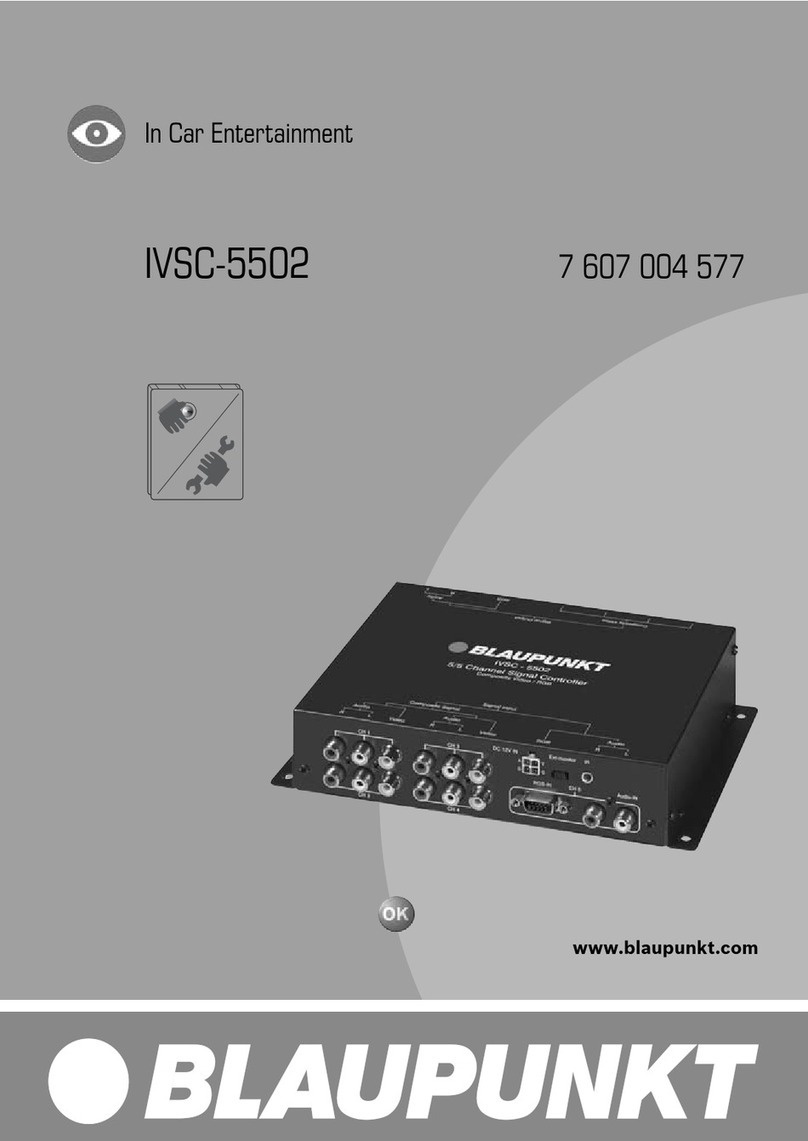
Blaupunkt IVSC-3302 Specification sheet

In Car Video
IVSC-3302
Bedienungs- und Einbauanleitung
Operating and installation instructions
Guide d’utilisation et de montage
Istruzioni d’uso e di installazione
Gebruiksaanwijzing en inbouwhandleiding
Bruks- och monteringsanvisning
Instrucciones de manejo e instalación
Instruções de serviço e de montagem
Betjenings- og monteringsvejledning
http://www.blaupunkt.com

2
INHALTSVERZEICHNIS
Allgemeines ............................. 3
Einbau- und Sicherheitshinweise ..... 3
Zubehör .......................................... 3
Lieferumfang ............................ 4
Ein-/Ausschalten ..................... 4
Einschalten des Signal Controllers .. 4
Ausschalten des Signal Controllers . 4
IR-Fernbedienung .................... 5
Funktionen ...................................... 5
Einstellungen für Audio OUT ........... 6
Einbau ...................................... 6
Einbau- und Sicherheitshinweise ..... 6
Plus-Anschluss ................................ 7
Schaltplus ....................................... 7
Sicherungen (Fuse) ......................... 7
Minus (Masse)-Anschluss ................ 7
Technische Daten .................... 8
Ausstattung ..................................... 8
Anschlussbilder ..................... 59

DANSK
3
ENGLISH DEUTSCH
FRANÇAIS
ITALIANO
NEDERLANDS
SVENSKA
ESPAÑOL
PORTUGUÊS
Allgemeines
VielenDank,dassSiesichfüreinBlau-
punkt Produkt entschieden haben. Wir
wünschen Ihnen viel Freude an Ihrem
neuen Gerät.
LesenSiebittevorderersten Benut-
zung diese Bedienungsanleitung.
Die Blaupunkt Redakteure arbeiten
ständigdaran,dieBedienungsanleitun-
gen übersichtlich und allgemein ver-
ständlich zu gestalten. Sollten Sie den-
noch Fragen zur Bedienung haben, so
wenden Sie sich bitte an Ihren Fach-
händler oder an die Telefon Hotline Ih-
res Landes. Die Rufnummer finden Sie
auf der Rückseite dieses Heftes.
FürunsereinnerhalbderEuropäischen
Union gekauften Produkte, geben wir
eineHerstellergarantie.DieGarantiebe-
dingungen können Sie unter
www.blaupunkt.de abrufenoderdirekt
anfordern bei:
Blaupunkt GmbH
Hotline
Robert Bosch Str. 200
D-31139 Hildesheim
Einbau- und Sicherheitshinweise
Bevor Sie Ihren Signal Controller an-
schließen, lesen Sie bitte sorgfältig die
folgenden Hinweise.
Für die Dauer der Montage und des
Anschlusses ist der Minuspol der
Batterie abzuklemmen.
Hierbei sind die Sicherheitshinweise
des Kraftfahrzeug-Herstellers (Airbag,
Alarmanlagen,Bordcomputer,Wegfahr-
sperren) zu beachten.
Vor dem Bohren von Löchern müssen
Sie sicherstellen, daß keine verlegten
Kabel oder Fahrzeugteile beschädigt
werden.
Wählen Sie für den Einbau des Gerä-
tes eine Stelle, an der der Signal Con-
trollerfestverschraubtwerdenkann,an
der es den Fahrer nicht behindert und
dieFahrzeuginsassenbeieinemabrup-
ten Halt, wie z.B. einer Notbremsung,
nicht gefährdet werden können.
DieIR-FernbedienungdarfnichtimAuf-
blasbereich von Airbags (Fahrer, Bei-
fahrerseite, Seitenairbags) oder im
Kopf-undKnie-Aufschlagbereich mon-
tiert werden.
Für den Einbauort und die Befestigung
mittels Klebepad ist die Haltekraft auf
derMontageoberflächedurchdenKun-
den hinsichtlich aller Belange zu prü-
fen und sicherzustellen.
Zubehör
Wir empfehlen von Blaupunkt zugelas-
senes Zubehör.
ALLGEMEINE HINWEISE

4
Lieferumfang
DerLieferumfangdiesesSignalControl-
lers enthältalleuntenaufgeführtenTei-
le.ÜberprüfenSie,obderLieferumfang
ihres Gerätes vollständig ist. Wenden
Sie sich bitte unverzüglich an Ihren
Händler, falls eines der aufgeführten
Teile fehlen sollte.
●Signal Controller 7 607 003 552
●Anschlusskabel
●Schrauben
●IR-Fernbedienung
●IR-Empfänger
●Bedienungs- und Einbauanleitung
LIEFERUMFANG
Ein-/Ausschalten
Einschalten des Signal
Controllers
Der Signal Controller wird über die
Schaltleitung„+12VIgnition“vomange-
schlossenenSteuergeräteingeschaltet.
Ausschalten des Signal
Controllers
Der Signal Controller wird über die
Schaltleitung „+12V Ignition“ vom an-
geschlossenen Steuergerät ausge-
schaltet.
EIN-/AUSSCHALTEN

DANSK
5
ENGLISH DEUTSCH
FRANÇAIS
ITALIANO
NEDERLANDS
SVENSKA
ESPAÑOL
PORTUGUÊS
IR-FERNBEDIENUNG
IR-Fernbedienung
Funktionen
Die mitgelieferte Fernbedienung ist ge-
eignet zur Bedienung des Signal-Con-
trollers und der Monitore.
Um einen einzelnen Monitor oder
auch alle Monitore gleichzeitig zu
steuernist die Eingabeeiner Tasten-
folgenotwendig.Dazu wirdzunächst
der Monitor (FRONT/LEFT/RIGHT-
OVERHEAD oder ALL) angewählt
und danach die gewünschte Funkti-
on ausgelöst. Die Monitor-Auswahl
bleibt so lange erhalten, bis erneut
eine der Tasten (FRONT/LEFT/
RIGHT-OVERHEAD oder ALL) ge-
drückt wird.
1POWER
Ein-/Aus-Taste für den oder die
angewählten Monitore.
2NAVI
Taste ohne Funktion.
3VOL • Pfeiltaste
Aufregeln der Lautstärke des an-
gewählten Monitors (nichtAudio
OUT).
VOL • Pfeiltaste
Abregeln der Lautstärke des an-
gewählten Monitors (nichtAudio
OUT).
4MUTE
Stummschaltung aller ange-
schlossenen Monitore undAudio
OUT.
5CH • Pfeiltaste /
Anwahl der Eingangsquelle für
den angewählten Monitor.
6RIGHT
Anwahl des RIGHT / OVERHEAD
Monitors.
7OVERHEAD
Anwahl des RIGHT / OVERHEAD
Monitors.
8ALL
Anwahl aller Monitore.
9LEFT
Anwahl des linken Monitors.
:FRONT
Anwahl des Front Monitors.
IVRC 05
MUTE
NAVI
POWER
BOOSTER
FRONT
AUDIO CH VOL CH
ALL
RIGHT
LEFT
OVERHEAD
1
4
5
9
:
8
7
<
;
23
6

6
EINBAU
Einstellungen für Audio OUT
;AUDIO CH • Pfeiltaste /
Anwahl der Eingangsquelle für
Audio OUT.
Hinweis: Die Eingangsquelle
muß in der Lautstärke regelbar
sein.
<BOOSTER
Einstellung der Verstärkung für
Audio OUT /0 dB oder 10 dB.
Einbau
Einbau- und Sicherheitshinweise
Bevor Sie Ihren Signal Controller an-
schließen, lesen Sie bitte sorgfältig die
folgenden Hinweise.
Für die Dauer der Montage und des
Anschlusses ist der Minuspol der
Batterie abzuklemmen.
Hierbei sind die Sicherheitshinweise
des Kraftfahrzeug-Herstellers (Airbag,
Alarmanlagen,Bordcomputer,Wegfahr-
sperren) zu beachten.
Vor dem Bohren von Löchern müssen
Sie sicherstellen, daß keine verlegten
Kabel oder Fahrzeugteile beschädigt
werden.
Wählen Sie für den Einbau des Gerä-
tes eine Stelle, an der der Signal Con-
trollerfestverschraubtwerdenkann,an
der es den Fahrer nicht behindert und
dieFahrzeuginsassenbeieinemabrup-
ten Halt, wie z.B. einer Notbremsung,
nicht gefährdet werden können.
DieIR-FernbedienungdarfnichtimAuf-
blasbereich von Airbags (Fahrer, Bei-
fahrerseite, Seitenairbags) oder im
Kopf-undKnie-Aufschlagbereich mon-
tiert werden.
Für den Einbauort und die Befestigung
mittels Klebepad ist die Haltekraft auf
derMontageoberflächedurchdenKun-
den hinsichtlich aller Belange zu prü-
fen und sicherzustellen.
Hinweis:
BevorSie eineVerbindungzwischen
den Monitoren und Ihrem Signal
Controllerherstellen, überprüfenSie
IR-FERNBEDIENUNG

DANSK
7
ENGLISH DEUTSCH
FRANÇAIS
ITALIANO
NEDERLANDS
SVENSKA
ESPAÑOL
PORTUGUÊS
deneinwandfreien+/-undSchaltplus
Anschluß.
Plus-Anschluss
Sicherungshalter (Sicherung 1A) zur
Absicherung des Pluskabels (Perma-
nent (1), siehe Fig. 1) max. 30 cm von
der Fahrzeugbatterie entfernt am Plus-
pol anschließen (ggf. Loch in Spritz-
wand bohren und entsprechende Ka-
beldurchführung verwenden).
Schaltplus
Schaltpluskabel (2), siehe Fig. 1, an
Schaltplusausgang(Ignition )des
Grundgerätes anschließen (z.B.Auto-
radiooderNavigation)BeiAnschlußan
Klemme 15 vom Kfz. muß ein Siche-
rungshalter(Sicherung1A)zurAbsiche-
rung des Schaltpluskabels (2) max.
20 cm vomAnschlußpunkt entfernt an-
geschlossen werden.
Sicherungen (Fuse)
Bei dem Einsatz einer Ersatzsicherung
bitteniemalsSicherungenüberbrücken
oder gegen Typen mit höherem Strom
auswechseln.
Minus (Masse)-Anschluss
Die Minusleitung (Masse/GND, (3),sie-
he Fig. 1) direkt an die Karosserie an-
schrauben. Kontaktfläche des Masse-
punktes metallisch blank kratzen und
mitGraphitfetteinfetten(wichtigfürgute
Masseverbindung).
•SolltederEinbaudasBohrenvonLö-
chern oder andere Veränderungen
andemFahrzeugerfordern,wenden
Sie sich an eine Fachwerkstatt in Ih-
rer Nähe.
TECHNISCHE DATEN
Technische Daten
Video input:
Composite Video, 1,0 Vpp, 75 Ohm
Audio input:
0 - 1,0 Vrms, 20 Hz - 20 kHz
(Booster off)
0- 0,3 Vrms, 20 Hz - 20 kHz
(Booster on)
Video output:
Composite Video, 1,0 Vp-p, 75 Ohm
Audio output:
0- 1,0 Vrms, 20 Hz - 20 kHz
Stromversorgung:
DC 12V, +/- 10%, max. 4A
Betriebstemperatur:
-20°bis + 70°Celsius
Abmessungen:
205 x 45 x 146 mm (B x H x T)
Ausstattung
3 Audio Eingänge:
Cinch-Buchsen
3 Video Eingänge:
Cinch-Buchsen
3 Monitor-Ausgänge:
CCVS, 13 pin Buchse, mit Power,
Masse, Schaltplus und Steuerung
1 Audio Ausgang:
Cinch-Buchsen
10dB booster on/off
IR-Fernbedienung
IR Empfänger
Power input:
4pin Stecker
Metallgehäuse
EINBAU

8
CONTENTS
General information ................. 9
Installation and safety notices .......... 9
Accessories .................................... 9
Supplied parts ........................ 10
Switching on/off .................... 10
Switching on the signal controller .. 10
Switching off the signal controller .. 10
IR remote control ................... 11
Functions ...................................... 11
Settings for Audio OUT ................. 12
Installation.............................. 12
Installation and safety notices ........ 12
Positive connection ....................... 12
Switching positive ......................... 13
Fuse.............................................. 13
Negative (ground) connection ........ 13
Specifications ........................ 14
Features ........................................ 14
Connection diagrams ............. 59

DANSK
9
ENGLISH DEUTSCH
FRANÇAIS
ITALIANO
NEDERLANDS
SVENSKA
ESPAÑOL
PORTUGUÊS
General information
Thank you for choosing a Blaupunkt
product. We hope you enjoy using this
new piece of equipment.
Please read these operating instruc-
tionsbefore using theequipmentfor
the first time.
The Blaupunkt editors are constantly
working on making the operating in-
structions clearer and easier to under-
stand. However, if you still have any
questionsonhowtooperatethedevice,
please contact your dealer or the tele-
phone hotline for your country. You will
findthetelephonenumberprintedatthe
back of this booklet.
We provide a manufacturer guarantee
for our products bought within the Eu-
ropean Union. You can view the guar-
anteeconditionsatwww.blaupunkt.de
or ask for them directly at:
Blaupunkt GmbH
Hotline
Robert Bosch Str. 200
D-31139 Hildesheim
Installation and safety notices
Before connecting your signal control-
ler, please read the following informa-
tion carefully.
Thebattery’snegative terminal must
be disconnected for the entire time
ittakestoinstalland connectthis de-
vice.
When doing so, observe the vehicle
manufacturer’s safety notices(airbags,
alarm systems, trip computers, immo-
bilizers).
Beforedrillinganyholes,makesurethat
no installed cables or vehicle compo-
nents can be damaged.
When installing the signal controller,
select a location in the vehicle that al-
lows you to attach it firmly into place
using screws. The installation location
should be such that the signal control-
ler does not get in the way of the driver
and cannot endanger the occupants in
the event of the vehicle suddenly com-
ing to a halt, for instance, during an
emergency stop.
The IR remote control should not be in-
stalled within the inflation range of air-
bags (driver, passenger side, side air-
bags) or in any position where it could
be struck by the vehicle occupants’
heads or knees.
With regard to the installation location
and the attachment using an adhesive
pad, check and ensure that the holding
strength of the installation surface is
sufficient and suitable for all situations
and safety requirements.
Accessories
We recommend you use accessories
thathavebeenapprovedbyBlaupunkt.
GENERAL INFORMATION

10
Supplied parts
The signal controller is supplied with all
thepartslistedbelow.Pleasecheckthat
the range of parts supplied with your
device is complete. If one of the listed
parts is missing, please contact your
dealer immediately.
●Signal controller 7 607 003 552
●Connecting cable
●Screws
●IR remote control
●IR receiver
●Operating and installation instruc-
tions
SUPPLIED PARTS
Switching on/off
Switching on the signal
controller
The signal controller is switched on via
the “+12V ignition” switching line by the
connected control device.
Switching off the signal
controller
The signal controller is switched off via
the “+12V ignition” switching line by the
connected control device.
SWITCHING ON/OFF

DANSK
11
ENGLISH DEUTSCH
FRANÇAIS
ITALIANO
NEDERLANDS
SVENSKA
ESPAÑOL
PORTUGUÊS
IR REMOTE CONTROL
IR remote control
Functions
The supplied remote control is suitable
for operating the signal controller and
the monitors.
You mustentera buttoncombination
in order to control a single monitor
or all the monitors simultaneously.
To doso,youfirst select the monitor
(FRONT/LEFT/RIGHT-OVERHEADor
ALL) and then the function that you
require. The selected monitor or
monitorsremain(s)selecteduntilyou
press one of the buttons (FRONT/
LEFT/RIGHT-OVERHEAD or ALL)
again.
1POWER
On/off button for the selected
monitor or monitors.
2NAVI
Button has no function.
3VOL • arrow button
Increase the volume for the se-
lected monitor (notAudio OUT).
VOL • arrow button
Decrease the volume for the se-
lected monitor (notAudio OUT).
4MUTE
Mute the volume for all the con-
nected monitors and Audio OUT.
5CH • arrow button /
Select the input source for the se-
lected monitor.
6RIGHT
Select the RIGHT / OVERHEAD
monitor.
7OVERHEAD
Select the RIGHT / OVERHEAD
monitor.
8ALL
Select all monitors.
9LEFT
Select the left monitor.
:FRONT
Select the front monitor.
IVRC 05
MUTE
NAVI
POWER
BOOSTER
FRONT
AUDIO CH VOL CH
ALL
RIGHT
LEFT
OVERHEAD
1
4
5
9
:
8
7
<
;
23
6

12
INSTALLATION
Settings for Audio OUT
;AUDIO CH • Arrow button /
Select the input source forAudio
OUT.
Note: The volume of the input
source must be adjustable.
<BOOSTER
Setting the amplification forAudio
OUT
/
0 dB or 10 dB.
Installation
Installation and safety notices
Before connecting your signal control-
ler, please read the following informa-
tion carefully.
The battery’s negative terminal must
be disconnected for the entire time it
takestoinstallandconnectthisdevice.
When doing so, observe the vehicle
manufacturer’s safety notices(airbags,
alarm systems, trip computers, immo-
bilizers).
Beforedrillinganyholes,makesurethat
no installed cables or vehicle compo-
nents can be damaged.
When installing the signal controller,
select a location in the vehicle that al-
lows you to attach it firmly into place
using screws. The installation location
should be such that the signal control-
ler does not get in the way of the driver
and cannot endanger the occupants in
the event of the vehicle suddenly com-
ing to a halt, for instance, during an
emergency stop.
The IR remote control should not be in-
stalled within the inflation range of air-
bags (driver, passenger side, side air-
bags) or in any position where it could
be struck by the vehicle occupants’
heads or knees.
With regard to the installation location
and the attachment using an adhesive
pad, check and ensure that the holding
strength of the installation surface is
sufficient and suitable for all situations
and safety requirements.
IR REMOTE CONTROL

DANSK
13
ENGLISH DEUTSCH
FRANÇAIS
ITALIANO
NEDERLANDS
SVENSKA
ESPAÑOL
PORTUGUÊS
Note:
Before connecting the monitors to
yoursignal controller,check that the
+/- and switching positive connec-
tions are working properly.
Positive connection
Connect the fuse holder (1A fuse) to
protect the positive cable (permanent
(1), see Fig. 1). The fuse holder should
beconnected to thepositiveterminal at
adistanceof max. 30cm from thevehi-
cle battery (if necessary, drill a hole in
the bulkhead and use the appropriate
cable grommets).
Switching positive
Connecttheswitchingpositivecable(2)
(see Fig. 1) to the switching positive
output (ignition ) of the main de-
vice(e.g.carradioornavigationdevice).
If connecting to terminal 15 of the vehi-
cle, protect the switching positive cable
(2) by installing a fuse holder (1A fuse)
at a maximum distance of20cmfrom
the point of connection.
Fuse
If the fuse needs to be replaced, never
bypass/bridge the fuse and never re-
placeitwithfusetypesthataredesigned
for higher currents.
Negative (ground) connection
Attach the negative cable (1) (earth/
GND, (3), see Fig. 1) directly to the ve-
hicle body using a screw. Scratch the
surface down to the bare metal at the
point at which the ground is made.
•Iftheinstallationrequiresholestobe
drilled or any other changes to be
made to the vehicle, please contact
a specialist workshop in your area.
INSTALLATION

14
SPECIFICATIONS
Specifications
Video input:
Composite Video, 1.0 Vpp, 75 ohms
Audio input:
0 - 1.0 Vrms, 20 Hz - 20 kHz (Booster
off)
0 - 0.3 Vrms, 20 Hz - 20 kHz (Booster
on)
Video output:
Composite Video, 1.0 Vp-p, 75 ohms
Audio output:
0 - 1.0 Vrms, 20 Hz - 20 kHz
Power supply:
DC 12V, +/- 10%, max. 4A
Operating temperature:
-20°to + 70°Celsius
Dimensions:
205 x 45 x 146 mm (W x H x D)
Features
3 Audio inputs:
Cinch jacks
3 Video inputs:
Cinch jacks
3 monitor outputs:
CCVS, 13-pin jack, with power, earth,
switching positive and control
1 Audio output:
Cinch jacks
10dB booster on/off
IR remote control
IR receiver
Power input:
4-pin plug-type connector
Metal housing

DANSK
15
ENGLISH DEUTSCH
FRANÇAIS
ITALIANO
NEDERLANDS
SVENSKA
ESPAÑOL
PORTUGUÊS
TABLE DES MATIÈRES
Remarques générales ............ 16
Consignes d’installation
et de sécurité ................................ 16
Accessoires .................................. 16
Fourniture .............................. 17
Allumer / Éteindre ................. 17
Allumer le contrôleur de signaux .... 17
Éteindre le contrôleur de signaux ... 17
Télécommande infrarouge .... 18
Fonctions ...................................... 18
Paramètres pour la sortie audio ..... 19
Installation.............................. 19
Consignes d’installation
et de sécurité ................................ 19
Connexion (+) ............................... 20
(+) commuté.................................. 20
Fusibles (Fuse) ............................. 20
Câble (-) (masse) .......................... 20
Caractéristiques techniques .. 20
Équipement ................................... 20
Schéma électrique ................. 59

16
Remarques générales
Nous vous remercions d’avoir porté
votre choix sur un produit Blaupunkt et
noussommessûrs queceproduitvous
donnera toute satisfaction.
Avant la première mise en service,
lisez attentivement le présent mode
d’emploi.
LesrédacteursdeBlaupunkts’efforcent
constamment de rédiger les modes
d’emploi de la manière la plus claire et
la plus compréhensible. Si vous avez
toutefoisdesquestionsconcernantl’uti-
lisation de l’appareil, n’hésitez pas à
contacter votre revendeur ou le service
d’assistance téléphonique de votre
pays. Les numéros de téléphone figu-
rent au dos de cette brochure.
Nous offrons une garantie construc-
teur pour les produits achetés dans
l’Union Européenne. Si vous souhai-
tez consulter les conditions de garan-
tie, visitez notre site à l’adresse
www.blaupunkt.de ou adressez-vous
directement à :
Blaupunkt GmbH
Hotline
Robert Bosch Str. 200
D-31139 Hildesheim
Consignes d’installation et de
sécurité
Avant de raccorder le contrôleur de si-
gnaux, prière de lire correctement les
consignes suivantes.
Il est impératif de débrancher le pôle
(-) de la batterie pour la durée de
montage.
Respecter ce faisant les consignes de
sécuritéduconstructeurautomobile(air-
bags, alarmes, ordinateurs de bord,
systèmes anti-démarrage).
S’assurerden’endommageraucuncâ-
ble posé ou aucune pièce du véhicule
en perçant les trous.
Pour installer l’appareil, choisir un en-
droitoù le contrôleurdesignaux puisse
êtrevissé, negênantpasleconducteur
et ne mettant pas en danger les occu-
pants du véhicule en cas d’arrêt brus-
que, par ex. en cas de freinage in ex-
tremis.
La télécommande infrarouge ne doit
pas être installée dans la zone de gon-
flagedesairbags(conducteur,côtépas-
sager avant, airbags latéraux) ou dans
la zone de choc de la tête et des ge-
noux.
Pour le lieu d’installation et la fixation
aumoyendepattesadhésives,leclient
est prié de vérifier et de garantir l’adhé-
sion sur la surface de montage à tous
les égards.
Accessoires
Nous recommandons d’utiliser des ac-
cessoires autorisés par Blaupunkt.
REMARQUES GÉNÈRALES

DANSK
17
ENGLISH DEUTSCH
FRANÇAIS
ITALIANO
NEDERLANDS
SVENSKA
ESPAÑOL
PORTUGUÊS
Fourniture
Ce contrôleur de signaux est livré avec
touteslespiècesindiquéesci-dessous.
Vérifiez si la fourniture de cet appareil
estcomplète.Adressez-vous immédia-
tement à votre revendeur en cas d’ab-
sence de l’une de ces pièces.
●Contrôleur de signaux
7 607 003 552
●Câble de branchement
●Vis
●Télécommande infrarouge
●Récepteur infrarouge
●Guide d’utilisation et d’installation
FOURNITURE
Allumer / Éteindre
Allumer le contrôleur de signaux
Le contrôleur de signaux s’allume via
le câble de commutation « +12V Igni-
tion » de l’appareil de commande con-
necté.
Éteindre le contrôleur de
signaux
Le contrôleur de signaux s’éteint via
lecâble decommutation «+12V Igni-
tion
» de l’appareil de commande con-
necté.
ALLUMER / ÉTEINDRE

18
TÉLÉCOMMANDE INFRAROUGE
Télécommande infrarouge
Fonctions
La télécommande fournie permet de
commanderle contrôleurde signaux et
les écrans.
Pourcommanderen mêmetempsun
écran individuel ou tous les écrans,
ilest nécessairede taperun raccour-
ci clavier. Sélectionner d’abord
l’écran (FRONT/LEFT/RIGHTOVER-
HEAD ou ALL) et ensuite activer la
fonctionvoulue. Lasélectiond’écran
reste jusqu’à ce que l’une des
touches(FRONT/LEFT/RIGHT-OVE
R-
HEAD ou ALL) soit pressée.
1POWER
Touche Marche/Arrêt pour le ou
les écrans sélectionnés.
2NAVI
Touche sans fonction.
3VOL • Touche flèche
Réduction du volume de l’écran
sélectionné (pasAudio OUT).
VOL • Touche flèche
Augmentation du volume de
l’écran sélectionné (pasAudio
OUT).
4MUTE
Coupure du son de tous les
écrans connectés etAudio OUT.
5CH • Touche flèche /
Sélection de la source d’entrée
pour l’écran sélectionné.
6RIGHT
Sélection de l’écran RIGHT /
OVERHEAD.
7OVERHEAD
Sélection de l’écran RIGHT /
OVERHEAD.
8ALL
Sélection de tous les écrans.
9LEFT
Sélection de l’écran gauche.
:FRONT
Sélection de l’écran avant.
Paramètres pour la sortie audio
IVRC 05
MUTE
NAVI
POWER
BOOSTER
FRONT
AUDIO CH VOL CH
ALL
RIGHT
LEFT
OVERHEAD
1
4
5
9
:
8
7
<
;
23
6

DANSK
19
ENGLISH DEUTSCH
FRANÇAIS
ITALIANO
NEDERLANDS
SVENSKA
ESPAÑOL
PORTUGUÊS
INSTALLATION
;AUDIO CH • Touche flèche /
Sélection de la source d’entrée
pour Audio OUT.
Note : La source d’entrée doit
être réglable en volume.
<BOOSTER
Réglage de l’amplification pour
Audio OUT /0 dB oder 10 dB.
Installation
Consignes d’installation et de
sécurité
Avant de raccorder le contrôleur de si-
gnaux, prière de lire correctement les
consignes suivantes.
Il est impératif de débrancher le pôle
(-) de la batterie pour la durée de
montage.
Respecter ce faisant les consignes de
sécuritéduconstructeurautomobile(air-
bags, alarmes, ordinateurs de bord,
systèmes anti-démarrage).
S’assurerden’endommageraucuncâ-
ble posé ou aucune pièce du véhicule
en perçant les trous.
Pour installer l’appareil, choisir un en-
droitoù le contrôleurdesignaux puisse
êtrevissé, negênantpasleconducteur
et ne mettant pas en danger les occu-
pants du véhicule en cas d’arrêt brus-
que, par ex. en cas de freinage in ex-
tremis.
Latélécommandeinfrarougenedoitpas
être installée dans la zone de gonflage
desairbags(conducteur,côtépassager
avant,airbagslatéraux)oudanslazone
de choc de la tête et des genoux.
Pour le lieu d’installation et la fixation
aumoyendepattesadhésives,leclient
est prié de vérifier et de garantir l’adhé-
sion sur la surface de montage à tous
les égards.
Note :
Avant de relier les écrans et le con-
trôleur de signaux, vérifier la con-
nexion du +/- commuté.
TÉLÉCOMMANDE
INFRAROUGE

20
Connexion (+)
Raccorder le porte-fusible (fusible 1A)
pour protéger le câble (+) (Permanent
(1), cf. Fig. 1) au pôle (+) à 30 cm max.
de la batterie du véhicule (percer si né-
cessaire un trou dans le tableau
d’auvent et utiliser un passe-câble cor-
respondant).
(+) commuté
Raccorderle câble(+) commuté (2), cf.
Fig. 1, à la sortie (+) commuté (alluma-
ge )del’appareilprincipal(parex.
autoradio ou navigation). En cas de
connexion à la broche 15 du véhicule,
un porte-fusible (fusible 1A) doit être
connectéà20cmmax.dupointdecon-
nexion pour protéger le câble (+) com-
muté.
Fusibles (Fuse)
En cas d’utilisation d’un fusible de rem-
placement,nejamaisponterlesfusibles
oulesremplacerpardesmodèlesd’une
intensité supérieure.
Câble (-) (masse)
Visser le câble (-) (masse/GND, (3),cf.
Fig. 1) directement sur la carrosserie.
Gratter la surface de contact du point
de masse pour la rendre bien métalli-
que et la graisser avec de la graisse
graphite (important pour assurer une
bonne mise à la masse).
•Si l’installation devait demander le
perçagede trous ou d’autres modifi-
cations sur le véhicule, s’adresser à
unservice de réparation profession-
nel proche de chez vous.
Caractéristiques techniques
Entrée vidéo :
Composite Vidéo, 1,0 Vpp, 75 ohms
Entrée audio :
1,0 Vrms, 20 Hz - 20 kHz Booster off)
(Booster off)
00,3 Vrms, 20 Hz - 20 kHz Booster on)
Sortie vidéo :
Composite Vidéo, 1,0 Vp-p, 75 ohms
Sortie audio :
1,0 Vrms, 20 Hz - 20 kHz
Alimentation :
CA12V, +/- 10%, max. 4A
Température de service :
-20∞à + 70∞Celsius
Dimensions :
205 x 45 x 146 mm (L x H x P)
Équipement
3 Entrées audio :
Prises cinch
3 Entrées vidéo :
Prises cinch
3 Sorties écran :
CCVS, prise 13 pin, avec Power,
Masse, (+) commuté et Commande
1 Sorties écran :
Prises cinch
10dB booster on/off
Télécommande infrarouge
Récepteur infrarouge
Entrée courant :
Connecteur 4pin
Boîtier métallique
INSTALLATION CARACTÉRISTIQUES
TECHNIQUES
Table of contents
Languages:
Other Blaupunkt Controllers manuals