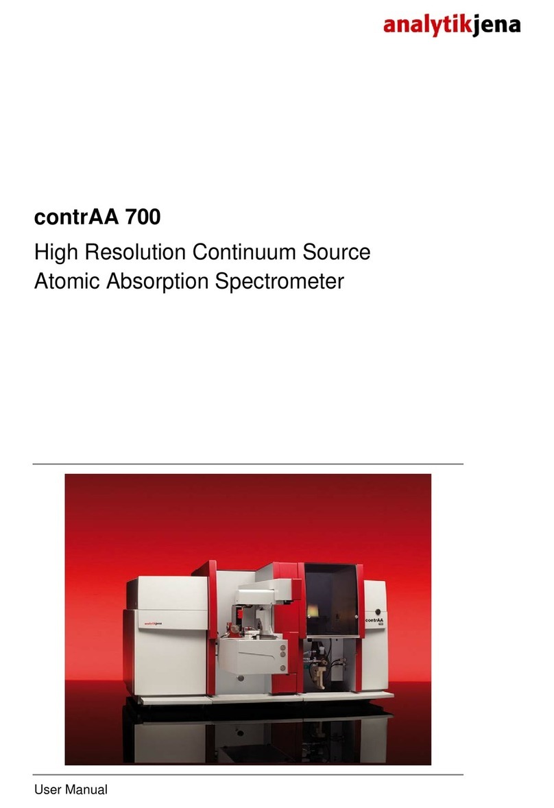
Analytic Jena contrAA 300 User manual

contrAA 300
High-Resolution Continuum Source
Atomic Absorption Spectrometer
Operating manual

Service:
Analytik Jena AG
Customer
Services
Konrad
-Zuse-Str. 1
07745 Jena
Germany
Phone:
Hotline: + 49 (0) 3641 / 77-7407
Fax: + 49 (0) 3641 / 77-7449
Email:
service@analytik-jena.de
General information about Analytik Jena AG
on the internet: http://www.analytik-jena.de
Copyrights and Trademarks
contrAA is a registered trademark of Analytik Jena AG in Germany.
Microsoft, Windows 7/8, MS Excel are registered trademarks of Microsoft Corp.
The identification with ® or TM is omitted in this manual.
Documentation number: 160:002.23
Edition – January 2014
Implementation of the Technical Documentation:
Analytik Jena AG
This publication describes the state of this product at the time of publishing. It need not necessarily
agree with future versions of the product.
Modifications reserved!
© Copyright 2014 Analytik Jena AG

Contents
contrAA 300 Issue 01/2014 1
Contents
1Basic information ............................................................3
1.1 User manual conventions......................................................................3
1.2Intended use .........................................................................................3
2Safety instructions ..........................................................5
3Specifications ..................................................................9
3.1 Technical data .......................................................................................9
3.1.1 contrAA 300 .....................................................................................................9
3.1.2 Control computer............................................................................................11
3.1.3 Flame technique.............................................................................................11
3.1.4 Accessories....................................................................................................12
3.2 Guidelines and standards ...................................................................14
4Installation requirements..............................................15
4.1 Ambient conditions ..............................................................................15
4.2 Floor space requirements and weight.................................................16
4.3 Energy supply .....................................................................................17
4.4 Gases used in flame mode .................................................................17
4.5 Laboratory fume hood .........................................................................18
4.6 System layout & general view .............................................................19
5Functions and design of the contrAA 300...................21
5.1 Basic unit.............................................................................................21
5.1.1 Physical measuring principle of HR-CS AAS .................................................21
5.1.2 Xenon lamp ....................................................................................................23
5.1.3 Flame system.................................................................................................24
5.2 Accessories for flame technique .........................................................29
5.2.1 AS-F and AS-FD Autosamplers .....................................................................29
5.2.2 JUN-AIR 6/S Piston Compressor ...................................................................31
5.2.3 SFS 6 Injection Module ..................................................................................31
5.2.4 Scraper – Automatic burner head cleaner for nitrous oxide flame..................32
5.2.5 HPT burner head............................................................................................32
5.3 Supplementary accessories – Hg/hydride systems ............................33
6Installation and start-up................................................34
6.1 Supply and control connections ..........................................................34
6.2 Installation and start of ASpect CS software.......................................37
6.3 Flame technique..................................................................................38
6.3.1 Installation for manual sample supply ............................................................38
6.3.2 Installation for continuous operation mode / sample supply by autosampler..40

Contents
2 Issue 01/2014 contrAA 300
6.3.3 Uninstalling the autosampler AS-F/AS-FD .....................................................43
6.3.4 Installation of the SFS 6 Injection Module ......................................................44
6.3.5 Change of burner head ..................................................................................45
6.3.6 Installing the scraper at a later stage..............................................................45
6.3.7 Operation of the HPT burner head .................................................................46
6.4 Start-up of contrAA 300 with accessories ...........................................47
6.4.1 Turn-on sequence, daily start of work ............................................................47
6.4.2 Shutdown sequence.......................................................................................47
7Care and maintenance ..................................................49
7.1 Maintenance overview ........................................................................49
7.2 Basic device ........................................................................................50
7.2.1 Fuse change ..................................................................................................50
7.2.2 Cleaning the sample compartment.................................................................51
7.3 Xe lamp cooling...................................................................................51
7.4 Removing and installing the continuum source (Xe lamp)..................51
7.5 Burner-nebulizer system .....................................................................53
7.5.1 Disassemble burner-nebulizer system unit.....................................................54
7.5.2 Clean burner ..................................................................................................56
7.5.3 Clean Nebulizer..............................................................................................58
7.5.4 Clean mixing chamber....................................................................................58
7.5.5 Clean siphon ..................................................................................................58
7.5.6 Assemble burner-nebulizer system unit .........................................................59
7.5.7 Cleaning the sensor of the burner ..................................................................60
7.6 AS-F, AS-FD autosampler ..................................................................61
7.6.1 Washing the sample paths.............................................................................61
7.6.2 Washing the mixing cup of the AS-FD............................................................61
7.6.3 Replacing the canulas and guide on the autosampler arm.............................62
7.6.4 Replacing the intake tube...............................................................................63
7.6.5 Replacing the tube set for diluent and washing liquid at the AS-FD...............63
7.6.6 Replacing the dosing syringe .........................................................................64
7.6.7 Clean-up after cup overflow ...........................................................................64
7.7 Compressor JUN-AIR 6/S ...................................................................65
8Relocating the contrAA 300..........................................66
8.1 Preparing the contrAA 300 for relocation............................................66
8.2 Setting up the contrAA 300 .................................................................67
9Disposal .........................................................................68
10 EC Declaration of Conformity ......................................69

Basic information
User manual conventions
contrAA 300 Issue 01/2014 3
1 Basic information
1.1 User manual conventions
The following warning and information symbols are used in this manual:
Danger!
To be followed strictly to prevent physical injury.
Danger! Hot surface!
Touching hot surfaces may cause burns.
Hazardous electrical voltage; do not touch!
Emission of UV
radiation!
Explosion hazard, fire hazard.
Caution!
To be followed to avoid damage to the equipment.
Note
To be followed to obtain correct measurement results.
The manual uses the following conventions:
•Chapters and illustrations are numbered consecutively.
•Every illustration has its own caption.
•Instructions for actions/steps of operation are numbered consecutively
and united in action units.
•Menu and option sequences in software are subdivided by "/" and
printed in bold letters, e.g. File / Open. Buttons or keys are marked by
square brackets, e.g. [OK].
1.2 Intended use
The contrAA 300 Atomic Absorption Spectrometer is a PC-controlled device for
the sequential trace analysis of metals and non-metals in liquid and dissolved
samples. The contrAA 300 is a flame device providing the possibility to use the
hydride technique in combination with the Hydride System (HS) accessory.
Used together with an autosampler, the contrAA 300 can be used as automatic
multielement analyzer in routine analysis. First, the system is to be calibrated
sequentially for the elements to be analyzed. Then, the samples are measured
sequentially. Thus, after every sample measurement, the results of all elements
to be determined are available.
All spectrometer parameters, burner height and fuel gas settings, are set
automatically according to the stored method parameters, which may vary for
the different element lines. The complete system, i.e. basic device and
accessories, and data acquisition and analysis, are controlled by the Windows-

Basic information
Intended use
4 Issue 01/2014 contrAA 300
based control software. The analytical background is also determined
automatically and simultaneously at the analysis line. The control software
contains default parameters for methodical settings of an analysis line. The pre-
defined line parameter settings for all analyzable elements of the periodic
system (also called cookbook) make it easier to get started with analysis.
Besides, they can be used as a basis for user-defined multielement analysis
methods. The control software contains comprehensive presentation and
storage options for measured signals and parameters, GLP-compliant result
records and various options for quality control including the possibility of
keeping quality control cards.

Safety instructions
Intended use
contrAA 300 Issue 01/2014 5
2 Safety instructions
For your personal safety and for the troublefree and safe operation of the
contrAA 300, read this section carefully before starting it up.
Follow all safety instructions given in this manual and pay attention to all
messages and notes displayed on the screen by control software.
In addition, follow the safety instructions for system components of other
manufacturers (e.g. PC, printer, autosampler) supplied together with the device.
In particular, read and follow the safety notes given on the labels of reagents
and the information on their handling, storage and disposal.
Intended use!
The
contrAA 300 may only be used for the techniques of atomic absorption
spectrometry described in this manual.
Local regulations!
Comply with the local safety regulations relevant to the operation of the device
(e.g. occupational safety
regulations, accident prevention regulations).
References to potential hazards made in this manual do not replace the
relevant occupational safety regulations to be complied with.
Personnel!
The
contrAA 300 may only be operated by qualified persons who have been
additionally trained for this type of work and have familiarized with the infor
-
mation given in this manual and in the accompanying manuals of accessories
and system components.
Any work on electrical equipment may only be performed by qualified
and
approved electricians.
Explosion and fire protection
The
contrAA 300 must not be operated in explosion-risk environments.
Smoking is not allowed in the operating room of the
contrAA 300.
The operator is responsible for establishing a control regim
e that ensures that
nitrous oxide and acetylene connections are leak
-proof.
Device switch
-off in emergency situations!
Switch off the
contrAA 300 with the power switch on the right side panel.
Disconnect the power cable from the power outlet.
Switch
off installed system components with the power switch of the connected
multiple socket outlet, which should be placed in a way to allow fast access.
Caution!
In doing so, there is the risk of data loss and damage to the operating
system on the PC!

Safety instructions
Intended use
6 Issue 01/2014 contrAA 300
Electric shock!
The
contrAA 300 is powered by electrical voltage. Extremely hazardous
electrical voltages
are applied to several components in the system!
To ensure Protection Class I (protective earth connection) of the device,
connect the power plug of the device only to a power outlet with protective earth
conductor. The protective effect must not be undone by the use of an extension
cable without protective earth conductor.
For any work on the electrical equipment, make sure to switch off the
contrAA
300 and disconnect the power cable from the power outlet.
Only service technicians of Analytik Jena AG and authorized specialists are
allowed to remove the back panel of the device.
Only service technicians of Analytik Jena AG and specially qualified electricians
are allowed to open system components, particularly the housing of the xenon
lamp.
Operating materials, hazardous substances
The operator is responsible for the selection of the substances used in the
process as well as for their safe handling.
This applies, in particular, to
radioactive, infectious, toxic, corrosive, combustible, explosive and otherwise
hazardous substances.
In handling hazardous substances, comply with the relevant local safety
regulations and guidelines.
Always observe the not
es given on labels.
Always use labeled vessels, protective goggles and rubber gloves.
The
contrAA 300 may only be operated under an active laboratory fume hood
to withdraw ozone, combustion gases of samples, and toxic and combustible
byproducts of sample p
reparation.
Treat
biological samples in compliance with the relevant local regulations for
the handling of infectious material.
The operator is responsible for disposing of
waste material, such as filter
residues of the compressor, in an environmentally co
nscious manner and in
compliance with the relevant local regulations.
Combustible and explosive gases
Be careful if acetylene is escaping! Acetylene is an explosive gas that is easily
detected by its smell.
Shut down the contrAA
300 if gas paths are leaking and fuel gas valves or
safety devices of the automatic gas control system are defective.
Keep vessels holding combustible solvents or samples containing volatile and
combustible substances away from the flame.
Xenon lamp and lamp housing
Inside t
he quartz bulb of the xenon lamp, there is an overpressure of 2 MPa,
which may increase up to 7
MPa in operation!
Only service technicians employed with or authorized by Analytik Jena AG are
allowed to open the lamp housing.

Safety instructions
Intended use
contrAA 300 Issue 01/2014 7
UV radiation and dazzling
hazard
Protect your eyes!
Never look at the radiation of the xenon lamp or the burner flame without
wearing UV protective goggles.
In flame mode, always keep the door of the sample compartment closed while
the flame is ignited.
The xenon lamp, in particu
lar, emits very intense light in the visible and UV
region!
Ozone
Inadmissibly high toxic ozone concentrations are produced by the interaction of
the UV radiation of the xenon lamp and the N
2O burner flame with the ambient
air.
The
contrAA 300 may only be operated under an active fume hood.
Operation of high
-pressure gas cylinders and gas plants
Fuel gas and oxidant are supplied by high
-pressure gas cylinders or local gas
plants.
Make sure to fully comply with the local safety regulations and guidel
ines
relevant to the operation of high
-pressure gas cylinders and gas plants.
High
-pressure tubes and pressure-reducing valves may only be used for the
specified gases.
Keep supply tubes, fittings and pressure
-reducing valves for N2
O (nitrous oxide)
free f
rom grease.
Weekly perform leak tests of all gas connections including nebulizer and mixing
chamber.
Carefully ventilate the cylinder location after having replaced the gas cylinder.
High temperatures
In flame mode, high temperatures are generated.
Allow for appropriate cooling times!
Do not touch hot components during or directly after measurements.
Allow for appropriate cooling times before undertaking maintenance or replacing
such components as burner head and lamps.
Keep combustible materials awa
y from the device.
Ventilation
Take care to ensure that the ventilation systems on the
contrAA 300 and the
accessory units are always functional. Covered vents, ventilation slots, etc. may
result in malfunction or damage to the device.
Cleaning and
maintenance
Except for the work described in Section "
Care and maintenance" p. 49,
service, maintenance and repair work on the
contrAA 300 may only be carried
out by service
technicians employed with or authorized by Analytik Jena AG.
Non
-compliance involves the risk of misalignment or damage to the device.

Safety instructions
Intended use
8 Issue 01/2014 contrAA 300
To externally clean the contrAA 300, only use a slightly moistened, but not
dripping cloth
.
For cleaning in the sample compartment of the
contrAA 300, take suitable
precautions, especially for the protection against contaminated and infectious
materials
.
Flame mode
Do not use pure oxygen or air enriched with oxygen as oxidant.
Ensure that the
flame sensor is always functional.
If gas paths are leaking, or if detect a fault on the fuel gas valves or the safety
devices of the automatic gas control system, switch off the
contrAA 300
until the
fault has been remedied.
Use the acetylene cylinder on
ly in an upright position and secured against
falling over. When the cylinder pressure drops below 100 kPa, replace the
cylinder to prevent acetone from entering the automatic gas control system.
Keep vessels holding combustible solvents and samples contai
ning volatile,
combustible constituents away from the flame.
Ignite and operate the flame only with the sample compartment door being
closed.
Never leave burning flames unattended.
The nebulizer pressure must not drop below 70 kPa.
When working with the
nitrous oxide flame, use a scraper or remove carbon
deposits manually with the scraper from the burner slot. For combustion gas
flows exceeding 250 NL/h pay attention to stubborn deposits. Remove these
where necessary to ensure the functionality of the scr
aper.
When carrying out maintenance work on the nebulizer/burner system, clean all
contaminated parts.
Sensitive electronics
Always electrically connect and disconnect any system components to the
contrAA
300, when they are switched off. This also applies when electrically
connecting system components with each other.

Specifications
Technical data
contrAA 300 Issue 01/2014 9
3 Specifications
3.1 Technical data
3.1.1 contrAA 300
Optical system
Reflecting optics with protective coating and optical system in light-proof casing
Monochromator Optimized high-resolution Echelle double monochromator. Pre-
monochromator with quartz prism. Wavelength accuracy
ensured through automatic neon wavelength correction
Wavelength range 185 – 900 nm
Spectral band width 2 pm at 200 nm
Grating Echelle grating
Optical bench
encased photometer
Optics mounted to solid base plate for stability and robustness.
Protection against humidity and waste gas.
Detector CCD line detector with high quantum efficiency and increased
UV sensitivity
Lamp
Xenon short-arc lamp with UV arc in hot spot mode; automatic hot-spot
tracking; simultaneous drift correction
Lamp current
9-16 A / 7 A Stand-by mode
Operating mode electrically modulated at 50 Hz
Power supply
Power supply unit integrated in spectrometer
Display modes
Absorption 0 … 3.99
Concentration Range of values: 5-place (0.001 … 99999), freely selectable unit
Energy 0 - 60000 counts
Signal analysis
Time resolved Mean value, maximum value of absorption, integral of
absorption
Spectrally resolved Spectrum with 50 to max. 200 pixels

Specifications
Technical data
10 Issue 01/2014 contrAA 300
Power supply
Power requirements
Frequency
110 - 230 V ±10 %
50/60 Hz
Other line voltages and frequencies on request
In-house line fuse
protection, installation side
16 A slow-blow
Power consumption Basic unit: 460 VA
Basic unit with PC, monitor and AS 52 Autosampler: 650 VA
Overvoltage Category
II acc. to DIN EN 61010-1
Pollution degree 2 acc. to DIN EN 61010-1
Protection Class
I
Degree of protection IP 20
When connecting components to the output socket additional to PC and
monitor, there is the risk of exceeding the admissible limit value of leakage
current.
Instrument fuses
Miniature fuses (5×20 mm) acc. to IEC 60127.
Line power input F1, F2 T 10 A/H
XE power supply
F3, F4
T 3.15 A/H
Ambient conditions
Corrosion protection Device is corrosion-proof against the samples to be analyzed
Operating temperature
+10 °C to 35 °C
Humidity Max. 90 % at +30 °C
Storage temperature
(desiccant)
–40 °C to +50 °C acc. to DIN 58390-2
Dimensions and weights
Weight 90 kg
Dimensions (W x H x D): 890 mm ×450 (540) mm ×545 mm

Specifications
Technical data
contrAA 300 Issue 01/2014 11
3.1.2 Control computer
Computer
(minimum requirements)
PC Pentium 1 GHz with 512 Mbyte RAM
40 Gbyte hard disk,
43-cm color monitor (17")
VGA graphic card
Resolution 800x600 Pixel or higher ,
CD ROM
Ports:
– Mouse port
– Printer port
- USB port (USB 1.1 or 2.0) for contrAA 300
Printer HP DeskJet Ink Jet Printer
HP Laser Jet Laser Printer
Operating system Windows XP Professional
3.1.3 Flame technique
Flame types
Acetylene/air Single-slot burner 50 mm, coded (standard)
Single-slot burner 100 mm, coded (optional)
Acetylene/nitrous oxide Single-slot burner 50 mm, coded
Oxidant
Compressed air and N2O (nitrous
oxide)
Inlet pressure: 300 to 600 kPa
Nebulizer flow rates
Air
N2O
400 to 600 NL/h
320 to 480 NL/h
Auxiliary oxidant (air or N2O) 30 to 315 NL/h
Total oxidant
Air
N2O
400 to 700 NL/h
320 to 700 NL/h
Fuel gas
Acetylene Inlet pressure: 80 to 150 kPa
Consumption: 40 to 315 NL/h
Nebulizer
Operating principle Pneumatic concentric jet nebulizer
Material Platinum/Rhodium tube, PEEK nozzle, PEEK cap
Nebulizer 0.7 Flow rate 4 to 7 mL/min

Specifications
Technical data
12 Issue 01/2014 contrAA 300
Siphon monitoring
Operating principle Float, corrosion-proof
Burner adjustment
Height 4 to 16 mm, automated
Rotation 0 to 90 degrees, manual
Safety circuits
Monitoring Burner and burner type
Fuel as pressure
Oxidant pressure and flow rate
Siphon fill level
Flame
Oxidant inlet pressure (air and N2O)
Fill level of waste bottle
3.1.4 Accessories
Autosampler AS-F
Autosampler without dilution function, completely PC-controlled
Sample tray 139/ 15
Sample cups
Special cups
129 pieces, 15 mL
10 pieces, 50 mL
Sample tray 54/ 50
Sample cups
54 pieces, 50 mL
Power supply Via AAS basic instrument
Wash bottle 2 L
Mass 6.5 kg

Specifications
Technical data
contrAA 300 Issue 01/2014 13
Autosampler AS-FD
Autosampler with dilution function, completely PC-controlled
Sample tray 139/ 15
Sample cups
Special cups
129 pieces, 15 mL
10 pieces, 50 mL
Sample tray 54/ 50
Sample cups
54 pieces, 50 mL
Dosing unit in the Fluidik module 5 mL
Power supply
Via AAS basic instrument
Wash bottle 2 L
Bottle for diluent
2 L
Mass (total)
Autosampler
Fluidik module
10.0 kg
6.5 kg
3.5 kg
Injection Module SFS 6
PC-controlled
Sample volume for single analysis 300 µL (minimum volume)
Power supply Via spectrometer
Piston Compressor JUN-AIR 6/S Standard
Tank capacity 15 L
Dimensions (diameter ×height) 400 mm ×480 mm
Power supply 230 V, 50 Hz
Weight
28 kg

Specifications
Guidelines and standards
14 Issue 01/2014 contrAA 300
3.2 Guidelines and standards
Protection Class and Degree of Protection
The contrAA 300 is classified in Protection Class I.
The Degree of Protection of the casing is IP 20.
Device safety
The contrAA 300 complies with the following safety standards
•DIN EN 61010-1 (VDE 0411T.1; IEC 1010-1)
•DIN EN 61010-2-061 (IEC 1010-2-061)
Electromagnetic Compatibility (EMC)
The contrAA 300 has been tested for radio interference suppression and noise
immunity. It complies with the requirements of
•DIN EN 61326
EC Directives
The contrAA 300 has been manufactured and tested in compliance with
standards that meet the requirements of EC Directives 73/23/EEC and
89/336/EEC. The device was delivered in perfect, technically safe condition. To
maintain this condition and ensure safe operation, observe the safety and
operating instructions given in this manual. In addition, observe the operating
instructions supplied along with accompanying accessories and system
components of other manufacturers.

Installation requirements
Ambient conditions
contrAA 300 Issue 01/2014 15
4 Installation requirements
The device may only be set up, installed and repaired by
service
technicians employed with or authorized by Analytik Jena AG. Any
unauthorized tampering with the device will limit the rights to claim under
warranty.
To set up the device, an assistant will be needed temporarily. The service
technician will test the device and record the test in the test report of the
contrAA 300.
The operator of the device is responsible everything not included in the scope of
delivery of the contrAA 300, but needed for its operation. The operation of the
contrAA 300 necessitates that certain technical requirements be met:
•Suitable installation site
•Sufficient floor space
•Ambient conditions
•Supply of fuel gas and oxidant
•Laboratory fume hood
•Mains connection
Pay attention to the instructions given in Section "
Safety instructions" p.5.
See to it that occupational safety
regulations are complied with. References to
potential hazards do not replace the valid occupational safety regulations!
Potential hazards when working with the contrAA 300 include:
•Burn hazard by flame and hot burner components
•Hazard from electric current
•UV radiation hazard
•Hazard from the generation of ozone and nitrogen oxides
•Hazard in handling high-pressure gas cylinders
•Hazard from toxic and chemically aggressive substances
4.1 Ambient conditions
•Do not set up the contrAA 300 directly beside a door or window. The
installation site of the contrAA 300 should be free of draft, dust, corrosive
vapors and vibrations.
•Do not set up the contrAA 300 near sources of electromagnetic
interference.
•Avoid direct exposure of the contrAA 300 to sunlight and radiation from
heaters. In extreme cases, provide room air conditioning.

Installation requirements
Floor space requirements and weight
16 Issue 01/2014 contrAA 300
•You are advised to prepare samples and store wet-chemical materials in
a separate room.
•In the operating room of the contrAA 300, smoking is not allowed.
•Operating temperature range: +10 °C to 35 °C
•Storage temperature range -40 °C to 55 °C,
use of a desiccant.
•Operating humidity max. 90 % bei 30 °C
•Storage humidity 10 % to 30 %,
use of a desiccant
4.2 Floor space requirements and weight
•Minimum size of work bench:
1880 mm ×700 mm, height to be selected according to ergonomic
aspects
•Carrying capacity of work bench: 120 kg
•Bench surface quality: wipe-proof, scratch-proof and corrosion-proof, not
moisture-absorbing
Set up the work bench to allow easy access from all sides.
Component Width [mm] Height [mm] Depth [mm] Weight [kg]
On the work bench
contrAA 300 800 650 700 90
AS-F 340 350 460 6,5
AS-FD
Autosampler
Fluidik module
340
360
350
310
460
165
6,5
3,5
Under the work bench
Compressor JUN-
AIR 6/S
∅400 480 28
Table 4-1 Dimensions and weights of the contrAA 300 and its system components

Installation requirements
Energy supply
contrAA 300 Issue 01/2014 17
4.3 Energy supply
Correct electrical mains supply!
For the electrical installation, observe the
relevant national and local
regulations!
The power outlet must be correctly earthed.
Do not use an adapter in the mains supply line.
Do not use any automatic circuit breakers.
The contrAA 300, PC, monitor and printer are to be connected to a power outlet
via a common multiple socket outlet and thus to the same phase. To avoid
abrupt voltage fluctuations, do not connect the contrAA 300 to a circuit, to which
other high energy consuming equipment has been connected.
Line power requirements
Voltage 110/230 V ±10 %
or other voltage as specified in Supply Contract
Frequency 50/60Hz
or other frequency as specified in Supply Contract
Power consumption Basic device: 450 VA
Basic device with PC, monitor and AS-FD Autosampler:
650 VA
Fuse protection 16 A, slow blow
4.4 Gases used in flame mode
Operation in flame mode requires the use of an oxidant (compressed air and
N2O, if necessary) and acetylene as fuel gas. The purity of the gas used is of
crucial importance for the analysis. Compressed air supply is provided by the
JUN-AIR 6/S Piston Compressor. If you intend to use an existing in-house
compressed-air supply system, please consult the Service Department of
Analytik Jena AG. N2O supply is via high-pressure gas cylinders or an in-house
supply system.
Installation of high
-pressure gas cylinders
If fuel gas supply is from high
-
pressure cylinders, the cylinders must be installed
upright in gas cylinder cabinets or mounted to the wall with cylinder holders
outside the laboratory room.
The pressure gas tubes are supplied with the device, the pressure-reducing
valves are optional.
•Tube length for connection to cylinder 5 m
•Tube length for connection to compressor 5 m
On request, you may also use tubes of other lengths. If you intend to do so,
please consult the Service Department of Analytik Jena AG.

Installation requirements
Laboratory fume hood
18 Issue 01/2014 contrAA 300
Fuel gas and oxidant
Inlet pressure
Consumption
Compressed air, oil-free, grease-free,
particle-free
300 to 600 kPa Max. 700 NL/h
N2O, oil-free, grease-free, purity 2.5 300 to 600 kPa Max. 700 L/h
Acetylene
Purity 2,5 (for flame photometry): better
than 99.5 Vol% relative to C2H2,without
acetone.
Minor constituents: Hydrogen compounds of
As, S and P
80 to 150 kPa Max. 315 NL/h
Table 4-2 Gases for flame technique
4.5 Laboratory fume hood
Laboratory fume hood
Do not operate the
contrAA 300 without fume hood!
Direct waste gas to the outside and avoid blockage!
The laboratory fume hood shall exhaust noxious combustion residues of the
flame and any produced ozone. Ozone is produced by the interaction of air and
the UV radiation emitted by the xenon lamp and the burner flame. The used
fume hood should be made of material that is resistant to heat and corrosion.
The first six meters of the fume hood should be made of metal.
Parameters Properties
Material
V2A
Exhaust capacity with nitrous oxide flame Approx. 8 to 10 m3/min
Exhaust capacity with air flame
Approx. 5 m
3
/min
Hood opening Approx. 200 × 200 mm
Distance to top edge of device
Approx. 200 to 300 mm
Tube diameter Approx. 100 to 120 mm
Table 4-3 Laboratory fume hood requirements
Table of contents
Other Analytic Jena Laboratory Equipment manuals
Popular Laboratory Equipment manuals by other brands

Bruker
Bruker NMR AVANCE NEO Systems user manual

Thermo Scientific
Thermo Scientific 88870007 Operation manual

IKA
IKA T 25 digital ULTRA-TURRAX operating instructions

Gilson
Gilson PIPETMAX 268 INSTALLATION QUALIFICATION/OPERATIONAL QUALIFICATION PROCEDURES

Agilent Technologies
Agilent Technologies 708-DS Training manual

Gibertini
Gibertini Crystal Series instruction manual