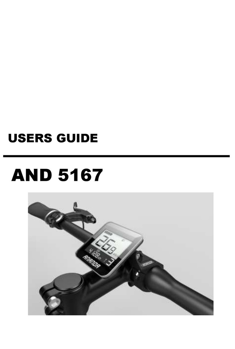
Ananda D10 PC5 User manual

- -
USERS GUIDE
D10 PC5/ D10 PU5

NEW ANDANDA DRIVE TECHNIQUES(SHANGHIA) CO.,LTD
目录
1. Preface.......................................................................1
2. Dimension&Materials...........................................................
2
3. Functions .............................................................3
4. Screen ........................................................................4
5. Warnings........................................................................4
6. Installation..............................................................................
4
7. Operations..............................................................................
5
7.1 ON/OFF..........................................................................5
7.2 Speed/ODO/Time……………….…………………...5
7.3 Lighting
ON/OFF.............................................................6
7.4 6km/h Assistance.............................................................7
7.5 Assistance
level..................................................................7
7.6 Battery capacity .......................................................8
7.7Background light ……………………………8
7.8 Error Code……………………………………………8
8. EXW Setting........................................................................9
8.1 Setting...........................................................................10
8.2 Background light adjustment............................10
8.3 Speed
Limit.....................................................................10

- -
8.4 Unit..................................................................................1
1
8.5 Battery
information.......................................................13
8.6 Software
Version...........................................................13
8.7 ISO setting....................................................................15
8.8 Save/quite...............................................................16
9. Wiring digram..................................................................16
10. Display printing code..........................................................16
11. FAQ&Answers..........................................................16
12. Guarantee&Warranty..................................................17
13. Edition updated..................................................................17
1


- 1 -
1. Perface
Dear Customer, we ask you please kindly study this
manual for D10 PC5/ D10 PU5 to use your electric bike
better. We will try to present you necessary information
including installation, setting and normal use in most
clear words, and hope it helps to clear your possible
confusion or problems.

- 2 -
2. Dimension&Materials
D10 PC5/ D10 PU5 display includes screen and
control buttons, Screen is a combined set including
metal holder and glass plate. Cover of the display is
applicable for ambient temperatures ranges between-
20℃ and 60℃ while keeps excellent mechanical
property. It meets with the waterproof level of IP65.
Dimension (mm)

- 3 -
Screen of D10 PC5
Control Button of D10 PC5
D10 PC5/ D10 PU5 Control buttons kit is connected
to the bottom of the display. Here we will describe
the symbol as switch。+ as PLUS,— as Minus, as
lighting,as walk assistance。

- 4 -
3. Functions
(1)D10 PC5/ D10 PU5 shows below information:
◆Battery real time capacity
◆Speed(Real time speed、AVG speed、Max speed)
◆ODO(Trip and total mileage)
◆Trip time
◆Assistance level
◆Lighting status: ON/OFF
◆6km/h assistance status: ON/OFF
◆Error code
◆Settings include:Background light、speed limit、Unit、
ISO。
◆Software Version
◆Battery information
◆At riding, after shifting among AVG, MAX, TRIP, TIME,
it goes back to ODO;
◆At static status, it will not go back to
ODO interface after shifting among AVV,MAX, TRIP,
TIMEO。
(2)D10 PC5/ D10 PU5 background light automatically
adjusts according to ambient brightness. (3)D10
PC5/ D10 PU5 meets with the EN15194:2017 standard。
4. Screen
Batt.Capacity
setting
light
6KM/H
Speed

- 5 -
UI of
the
Display
5. Warnning
Please
be careful
to use the
display
safely, Do
not disconnect it when power is on; Avoid knock or
crash.
Have it repaired if not working properly.
6. Installation
D10 is a LCD display, please fix it around the
handle bar, Then connect it with controller and control
button.
7. Operations
7.1 ON/OFF
◆Press battery Power On button for activation if
battery is off, then display is turned on.
Speed unit
AVG SPEED
MAX SPEED
Asst.level
Error code
Range/time
Range unit

- 6 -
◆Hold on display ON/OFF button for 2.5s if battery
is on, display is turned off. Short press for
turning on if display is off.
If battery is on, hold on battery ON/OFF button to
turn off battery, system is closed; However, if
press the ON/OFF button 3s later, display is
restarted. If system is on, but stay unused for
10 minutes, display goes to sleep mode, current @
sleep mode is below 100ua.
If system is on, but stay unused after 60 minutes,
battery is turned off automatically to close the
system. However, Display could be waked up after 3
seconds by pressing battery ON/OFF button.
7.2 Speed/ODO/Time
Preset screen information includes real time speed,
ODO, Short press on/off for shift among real time
speed, OD, →AVG speed, Trip→Max Speed, trip time.
Hold on minus button for 3S at the interface of AVG speed,
Trip will clear AVE Speed, Trip, Max Speed and Trip time.。
Hold on minus button at the interface of Max speed, Trip time
will clear AVG speed, Trip, Max speed and trip time.
Clearing is not available at the interface of real speed, ODO.

- 7 -
Real time speed, ODO AVG speed, Trip
Max speed, Trip time
7.3 Lighting
◆AUTO-Mode:Display automatically switch on/off
light by sensor according to environment; under such
circumstance, short press LIGHTING button is not valid
for light ON or Off. Default set for display lighting
is Automode. 。

- 8 -
◆Manual Mode:Short press Light button at manual 仅在
mode to activate lighting; Short press again to cancel
lighting function.
Shift between Auto/Manual Mode: Press and Hold on
lighting button for more than 2s for shift(Default set
when display turned on is auto-mode, for which letter
”A” is showed in the screen, which is turned off when
shifted to manual mode..
Auto-mode interface

- 9 -
Manual Mode Interface
7.4 6km/h assistance
Press and Hold on assistance button to active 6km/h
assistance function, ebike runs at a stable speed
of 6km/h; Release the button will cancel the
function.

- 10 -
6km/h assistance interface
7.5 Assistance level adjustment
Short press PLUS or Minus button for shift of
assistance level which changes output of motor.
Default set for assistance has 5 levels, of which 1st
level is for the lowest output, 5th is for the highest
output.
Default set is the 1st level.
Assistance level is adjustable among at
0->1->2->3->4->5->4->3->2->1->0 at any interface excluding
setting interface.
1st level 5th level
7.6 Battery capacity
All 5 indicating lights on if battery is fully
charged; If capacity indication shifts between light
blinks and empty symbol, battery is under-voltage, needs
to be recharged. Battery capacity indication may vary
compared to below chart.
Capacity information

- 11 -
15%——29% First Segment
30%——44% Second Segment
45%——59% Third segment
60%——84% Fourth Segment
>=85% Fifth Segment
Full capacity Low capacity Under-voltage
7.7 Background light adjustment
◆Background light varies automatically according to
environmental lightness by integrated sensor at Auto-
Mode. Eg: Background light decreases if environment
darks down; increases if environment brightens up, so
riding information is easily available..
◆Light on/off , If lighting is manually turned
on,display background light darks down; Conversely,
brightens up if lighting is manually turned off.
7.8 Error Code
Display shows corresponding code if ECU has a
problem. Ebike shall not be put into use until the error
code is cleared .

- 12 -
Error code interface
Definition:
(1)CANBUS common error code definition:
Code
Definition
01
Phase current failure
02
Controller busbar overloaded
03
Controller hall failure
04
Brake/Throttle failure
05
Controller Temp. Failure
06
Motor Temp. Failure
07
Overloaded Failure
08
Controller communication failure
09
Controller over or under voltage
10
Other failure
30
Display communication failure

- 13 -
CANBUS New Norm error code:
Code
Definition
31
MCB failure: Base voltage failure,
Calculation cycle failure
32
TE communication failure
33
3.3V power failure
34
Buttons failure
35
Button failure
36
Torque unit voltage failure
37
Brake failure, speed sensor failure,
Inspection Hall failure
38
Temperature sensor failure
39
Base sampling overdue
40
Current feedback circuit failure
41
Drive voltage failure
42
Abnormal current
43
Motor phase loss, overtime for start
50
Torque unit voltage inspection
circuit failure

- 14 -
(2)UART common code definition:
code
definition
solution
21
Abnormal
current
check if 3 phase short bridged.
22
Throttle
failre
check if throttle recovered to original status
23
Phase loss
check if well ,cabled ,check if phasewire well
connected to controller.
24
Hall failure
check hall sensor well cabled.
25
Abnormal
brake
Check brake recovered before system on
30
Communicati
on failure
Check display well connected to controller
31
Button stuck
Check buttons stuck or not before system on
32
Power
supply
failure
Check power source 13V/3.3V
34
6KM button
failure
Check assistance button stuck or not

- 15 -
8. Display EXW settings
8.1 Setting interface:
Hold on Plus and Minus buttons at main interface when speed
is O to enter setting mode interface. Short press Plus button to shift
among background light, speed limit, unit, background light. Right
corner position “1” means common setting.。
Background light Unit
Press and hold on both Plus and Minus buttons for 2s for
passpoerd input(Defaulted as 6262)for hidden setting interface,
short press Plus to shift among Battery information, Version, ISO,
Battery information. Right corner position “2” means hidden setting.
Battery information Version ISO
Short press Plus or Minus when input password will change the
password. Short press ON/OFF button to shift among digits,.

- 16 -
Short press ON/OFF button at the fourth digit will save the new
password.
Password input interface
8.2 Background light
Short press Plus button at setting interface for shift to
background Light setting.
BL Means background lightness,Right corner position”1”
means common setting. There are 3 levels for lightness,
1st level for the darkest setting,2nd level for standard setting,3rd
level for the brightest。Default setting is 1。Short press ON/OFF
button to choose BL setting interface, then short press Plus or Minus
for increase or decrease background lightnes. Short press ON/OFF
again to save and quit.。
This manual suits for next models
1
Table of contents
Other Ananda Bicycle Accessories manuals
Popular Bicycle Accessories manuals by other brands

Shimano
Shimano DURA-ACE CS-R9200 manual

SR Suntour
SR Suntour HESC ATS Rear Motor System user manual

OLIGHT
OLIGHT MAGICSHINE RN 400 user manual

ROTOR
ROTOR ALDHU 3D Plus installation manual

Bosch
Bosch HERCULES Futura Compact 8 Translation of the original operating instructions

Cateye
Cateye CC-AT200W owner's manual