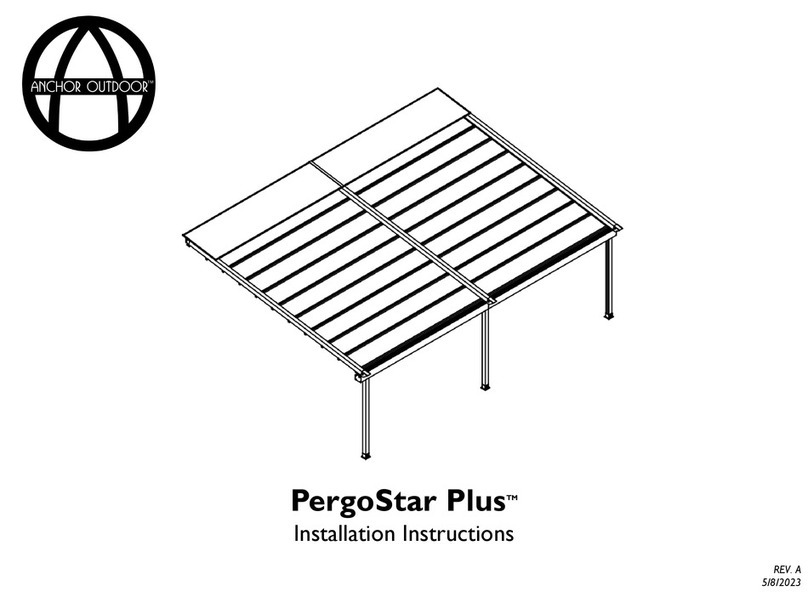
ANCHOR OUTDOOR PergoStar Romano User manual

PergoStar RomanoTM
Installation Instructions
REV. 1
7/17/2023

This installation manual is to be used in conjunction
with the installation videos that can be found on
YouTube.com/@AnchorIndustries
All details and information provided on the subsequent
pages are of general nature and may not refer to your
specific project.
2
Toscana by Anchor • PergoStar RomanoTM • Installation Instructions

3
Contents
-
Extrusion Glossary
4
-
Installation Tools
6
-Suggested Order of Installation
8
-
Assembly Instructions
Documentation
12
Frame & Fabric
16
Motor & Lights
33
Finishing Touches
40
-
Maintenance & Care
48
-
FAQ
50

Extrusion
Glossary
4

Contents
5
Extrusion Glossary
Uprights and Supports Upright Insert Light Cover Gutter Vertical Fixation Gutter Horizontal Fixation
Rafter Polycarbonate Support Motor Support Eave Purlin Mid Purlin
Transmission Tube Transmission Tube Insert Transmission Shaft Wall Flashing
Toscana by Anchor • PergoStar RomanoTM • Installation Instructions

Installation
Tools
6

Contents
7
Installation Tools
The following list details the minimum required tools to successfully install a Toscana
PergoStar RomanoTM. Other tools may be required depending on your project location or
configuration.
1. Ladder(s)
2. Metric Tape Measure
3. Level
4. Metric Hex Key Set
5. Metric Wrench Set
6. Drill and/or Driver(s)
7. Extended Length Phillips #2 Bits
8. Ratchet Wrench and Deep ½” or 13mm Socket
9. Phillips Screwdriver
10. Wire Nuts or Similar
11. Caulk and Caulk Gun
12. Project Specific Anchors and Necessary Equipment to Install Anchors
Note: Anchors to the ground or wall are not supplied.
Toscana by Anchor • PergoStar RomanoTM • Installation Instructions

Suggested
Order of
Installation
8

The following details the manufacturer’s suggested order of operations to successfully install your Pergostar. Though, adjustments may be
necessary depending on your specific project configuration or location.
1. Documentation. Locate and review the project pack list and customer detail drawing.These documents are located inside the miscellaneous parts box
inside a white envelope. Following the provided pack list, confirm that all components have been received.
2. Uprights. Connect the front uprights to the horizontal support and the rear uprights to the horizontal motor support using the provided hardware.
3. Rafters. Connect the rafters to the front and rear upright assemblies using the provided hardware. Depending on project location and orientation, it may
be easier to connect the rafters to the uprights first, then connect the rafter upright assembly to the horizontal supports.
4. Trolley Location. Position the lead trolley in the middle of each rafter. Ensure the locations are the same across all rafters.
5. Polycarbonate Support Beam. Connect the polycarbonate support beams to the rafters in the appropriate location(s) using the provided hardware
6. Transmission Tube. Connect the transmission tube to the rafters and motor using the provided hardware
7. Synchronizing Tube. Adjust the position of the lead trolleys as needed using the synchronizing tube.
8. Lead Eave Purlin. Assemble the eave purlin onto the fabric using the appropriate caps and joints.Tension the fabric using the provided hardware.
Connect the eave purlin to the lead trolley, ensuring to connect the tensioning fabric strip to the side of the fabric that will drain (tighten the nut to the
point where the purlin is slightly pushing on the white trolley bushing).
9. Mid Purlins. One row at a time, assemble the mid purlin (s) onto the fabric using the appropriate caps and joints.Tension the fabric using the provided
hardware. Connect the mid purlin to the appropriate trolley (tighten the nut to the point where the purlin is slightly pushing on the white trolley bushing).
Repeat until all mid purlins have been assembled.When lights are included, reference the customer information packet for the order in which the mid
purlins should be installed.
10. Top Eave Purlin. Assemble the eave purlin onto the fabric using the appropriate caps and joints.Tension the fabric using the provided hardware. Connect
the eave purlin to the rafter wall plate using the provided hardware.
11. Program. Program the motor and the lights (if applicable) using the instructions detailed in this instruction manual.
12. Frame Covering. Attach the frame covering to the pergola using the provided hardware.
13. Finishing Touches. Place the purlin end caps on each purlin. Attach the upright top-hole covers.Adjust lead trolleys as needed using the synchronizing
tube.
9
Suggested Order of Installation
Gazebo Configuration
Toscana by Anchor • PergoStar RomanoTM • Installation Instructions

The following details the manufacturer’s suggested order of operations to successfully install your Pergostar. Though, adjustments may be
necessary depending on your specific project configuration or location.
1. Documentation. Locate and review the project pack list and customer detail drawing.These documents are located inside the miscellaneous parts box
inside a white envelope. Following the provided pack list, confirm that all components have been received.
2. Uprights. Connect the front uprights to the horizontal support using the provided hardware.
3. Rafters. Remove the rafter wall bracket and mount to the desired location using appropriate anchors. Connect the rafter to the wall bracket using the
provided bolt. Connect the rafter to the front upright assembly using the provided hardware.
4. Motor Support Beam. Connect the motor support beam to the rafters in the appropriate location using the provided hardware.
5. Trolley Location. Position the lead trolley in the middle of each rafter. Ensure the locations are the same across all rafters.
6. Polycarbonate Support Beam. Connect the polycarbonate support beams to the rafters in the appropriate location(s) using the provided hardware
7. Transmission Tube. Connect the transmission tube to the rafters and motor using the provided hardware
8. Synchronizing Tube. Adjust the position of the lead trolleys as needed using the synchronizing tube.
9. Lead Eave Purlin. Assemble the eave purlin onto the fabric using the appropriate caps and joints.Tension the fabric using the provided hardware.
Connect the eave purlin to the lead trolley, ensuring to connect the tensioning fabric strip to the side of the fabric that will drain (tighten the nut to the
point where the purlin is slightly pushing on the white trolley bushing).
10. Mid Purlins. One row at a time, assemble the mid purlin (s) onto the fabric using the appropriate caps and joints.Tension the fabric using the provided
hardware. Connect the mid purlin to the appropriate trolley (tighten the nut to the point where the purlin is slightly pushing on the white trolley bushing).
Repeat until all mid purlins have been assembled.When lights are included, reference the customer information packet for the order in which the mid
purlins should be installed.
11. Top Eave Purlin. Assemble the eave purlin onto the fabric using the appropriate caps and joints.Tension the fabric using the provided hardware. Connect
the eave purlin to the rafter wall plate using the provided hardware.
12. Program. Program the motor and the lights (if applicable) using the instructions detailed in this instruction manual.
13. Frame Covering. Attach the frame covering to the pergola using the provided hardware.
14. Finishing Touches. Place the purlin end caps on each purlin.Attach the upright top-hole covers.Adjust lead trolleys as needed using the synchronizing
tube. Install wall flashing.
10
Suggested Order of Installation
With Post Configuration
Toscana by Anchor • PergoStar RomanoTM • Installation Instructions
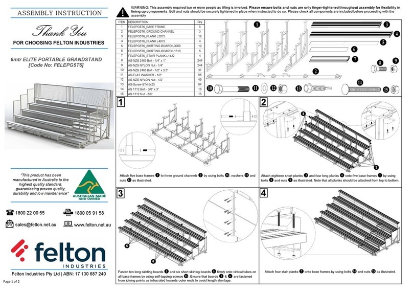
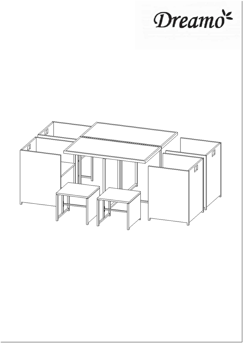
The following details the manufacturer’s suggested order of operations to successfully install your Pergostar. Though, adjustments may be
necessary depending on your specific project configuration or location.
1. Documentation. Locate and review the project pack list and customer detail drawing.These documents are located inside the miscellaneous parts box
inside a white envelope. Following the provided pack list, confirm that all components have been received.
2. Rafters. Remove the front and rear rafter wall bracket and mount to the desired location using appropriate anchors. Connect the rafters to the wall
brackets using the provided bolts.
3. Motor Support Beam. Connect the motor support beam to the rafters in the appropriate location using the provided hardware.
4. Trolley Location. Position the lead trolley in the middle of each rafter. Ensure the locations are the same across all rafters.
5. Polycarbonate Support Beam. Connect the polycarbonate support beams to the rafters in the appropriate location(s) using the provided hardware
6. Transmission Tube. Connect the transmission tube to the rafters and motor using the provided hardware
7. Synchronizing Tube. Adjust the position of the lead trolleys as needed using the synchronizing tube.
8. Lead Eave Purlin. Assemble the eave purlin onto the fabric using the appropriate caps and joints.Tension the fabric using the provided hardware.
Connect the eave purlin to the lead trolley, ensuring to connect the tensioning fabric strip to the side of the fabric that will drain (tighten the nut to the
point where the purlin is slightly pushing on the white trolley bushing).
9. Mid Purlins. One row at a time, assemble the mid purlin (s) onto the fabric using the appropriate caps and joints.Tension the fabric using the provided
hardware. Connect the mid purlin to the appropriate trolley (tighten the nut to the point where the purlin is slightly pushing on the white trolley bushing).
Repeat until all mid purlins have been assembled.When lights are included, reference the customer information packet for the order in which the mid
purlins should be installed.
10. Top Eave Purlin. Assemble the eave purlin onto the fabric using the appropriate caps and joints.Tension the fabric using the provided hardware. Connect
the eave purlin to the rafter wall plate using the provided hardware.
11. Program. Program the motor and the lights (if applicable) using the instructions detailed in this instruction manual.
12. Frame Covering. Attach the frame covering to the pergola using the provided hardware.
13. Finishing Touches. Place the purlin end caps on each purlin.Adjust lead trolleys as needed using the synchronizing tube. Install wall flashing.
11
Suggested Order of Installation
Between Wall Configuration
Toscana by Anchor • PergoStar RomanoTM • Installation Instructions

Assembly
Instruction
Documentation
12

Contents
13
Navigating Supplied Documentation
Pack List,Tags & Box Labels
Inside your pergola’s miscellaneous
parts box, you will be supplied with
a white packet containing pertinent
documents and drawings to your
project.
Within this packet you will find a
document labeled “TOSCANA BY
ANCHOR –PACK LIST” which will
detail how many of each item you
received and how they are tagged.
This will help to quickly identify each
part on site.
Each box received will also be
tagged with a label that will identify
which type of parts and quantities
are inside.
Project Specific Details
Part Tags
Box Labels
Toscana by Anchor • PergoStar RomanoTM • Installation Instructions
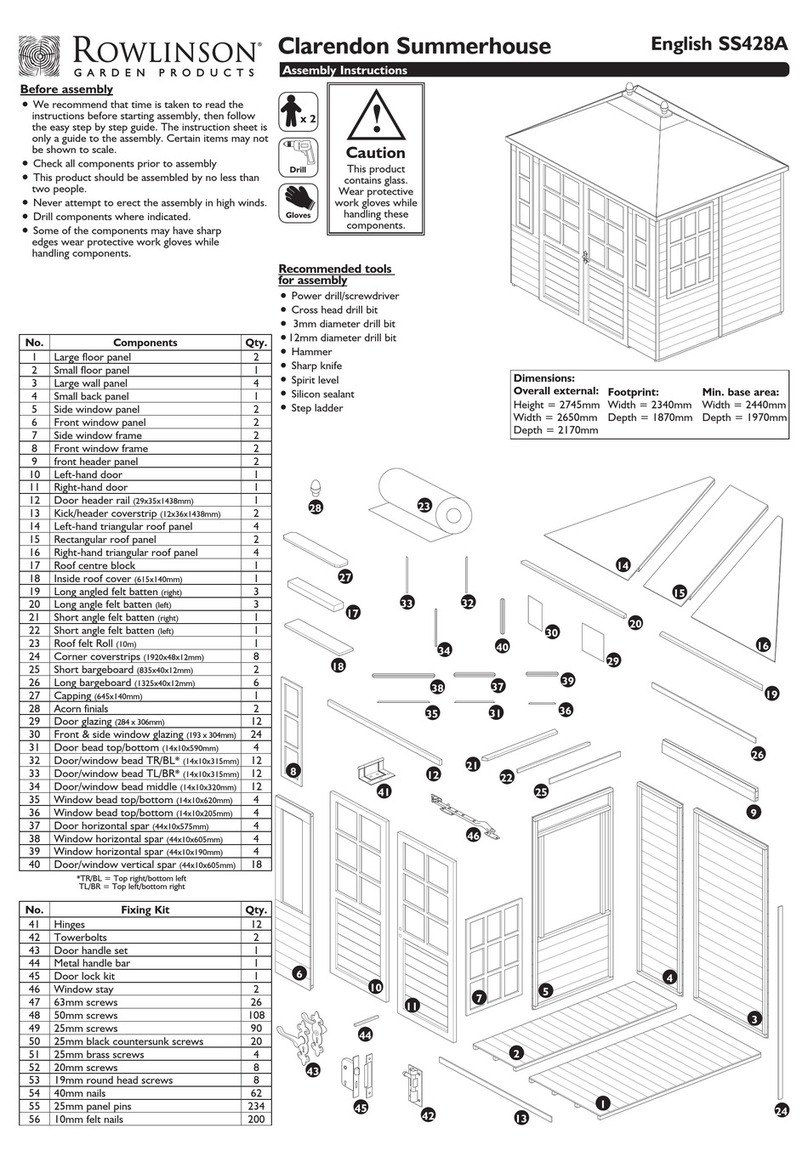
Contents
14
Navigating Supplied Documentation
Customer Detail Drawing
Within the customer information
packet, you will find a document
labeled “CUSTOMER DETAIL”. This
drawing will aid in identifying parts
and provide you with critical
measurements to ensure your
pergola is properly installed.
Note: Information and location of information will vary
based on the specifics of your project.
Example
Part Tag
General Location
of Motor
Toscana by Anchor • PergoStar RomanoTM • Installation Instructions
Contents
15
Navigating Supplied Documentation
Lighting Detail Drawing
Within the customer information
packet, you will find a document
labeled “LIGHTING DETAIL”. This
drawing will aid in the identifying the
order in which the mid purlins need
to be installed. If multiple light
circuits are present, this will be
noted.
Note: Information and location of information will vary
based on the specifics of your project.
Example Part Tag Direction of Purlin Wiring
Toscana by Anchor • PergoStar RomanoTM • Installation Instructions

Assembly
Instructions
Frame & Fabric
16

Your Pergostar will contain some or all of the
assemblies shown on the subsequent pages. Prior to
assembly, it is beneficial to identify which configuration
your specific pergola contains.
The table below is included in each of the subsequent
assembly pages and will help identify which assembly
may be present for each type of pergola configuration.
GZ = Gazebo
WP = With Post
BW = Between Walls
17
Configuration
GZ WP BW
X X
Toscana by Anchor • PergoStar RomanoTM • Installation Instructions
Uprights
Uprights and Horizontal Support Connections
18
First, remove the upright top cover and bolt,
set aside. Connect the upright and
horizontal support by aligning the horizontal
support bolts with the corresponding holes
on the upright. Secure in place using the
provided nylon locking nuts. For gazebo
configurations, repeat this step using the
rear uprights and horizontal motor support.
Note: Prior to connecting the horizontal support, ensure there is an
appropriate amount of bolt sticking out. Adjust as needed.
Configuration
GZ WP BW
X X
Toscana by Anchor • PergoStar RomanoTM • Installation Instructions

Top View

Rafters
Rafters to Front Upright Assembly
19
Configuration
GZ WP BW
X X
Toscana by Anchor • PergoStar RomanoTM • Installation Instructions
Top View
First, remove the belt tensioning bolt from the belt tensioner located at the end of the
rafter, set aside. Connect the upright and rafter end by aligning the rafter bolts with the
corresponding holes on the upright. Secure in place using the provided nylon locking nuts.
Install the belt tensioning bolt back in the tensioner through the upright through hole.
Ensure belt tensions are consistent across all rafters. For gazebo configurations, repeat
this step connecting the rafter top to the rear upright assembly.
Note: Prior to connecting the rafter, ensure there is an appropriate amount of bolt sticking out.
Adjust as needed.
Side View
Side View

Rafters
Rafter Top to Wall
20
Configuration
GZ WP BW
X X
Mount the rafter top weldment to the desired location
using the appropriate wall anchors. Secure the rafter to
the rafter top weldment using the supplied rafter bolt.
Note: Wall Anchors not supplied.
Toscana by Anchor • PergoStar RomanoTM • Installation Instructions
Table of contents
Other ANCHOR OUTDOOR Outdoor Furnishing manuals
Popular Outdoor Furnishing manuals by other brands

Four Seasons Courtyard
Four Seasons Courtyard Tank Hideaway 68903 owner's manual

Backyard Creations
Backyard Creations EDISON 272-1955 manual

Alice's Garden
Alice's Garden PADANO PNW150R6 Assembly instructions

Twin Star Home
Twin Star Home MS60-6760 Assembly instructions

Co-op
Co-op GOLD Use and care guide

Members Mark
Members Mark Sheffield GC-11680-4PC Assembly instructions & user manual