Seakeeper 7000 GYRO User manual

Product: Document #: Rev: Page:
SERVICE
BULLETIN MODEL 7 GYRO 9 57 1 1 of 6
Procedure: 24VDC INPUT POWER MODIFICATION FOR DELAYED SHUTDOWN
Description: Instructions for how to modify the 24VDC input power for delayed shutdown of Gyro Control J-Box
1. PURPOSE
This service bulletin describes how to install a time delay relay in the 24VDC input power to the Gyro
Control J-Box to delay the shutdown of power for 1.5 hours. This will allow the operator to initiate a
shutdown delay that runs the Gyro’s glycol cooling pump for 1.5 hours as the flywheel spools down
and then shuts off power to the Gyro Control J-Box.
2. PARTS REQUIRED
Item Part Number Scope of Supply Qty
Time Delay Relay, SPDT Magnecraft P/N: 821TD10H-UNI Customer Supplied 1
Switch, Maintained, SPST Teleflex Marine P/N: RK19650
(or equivalent)
Customer Supplied 1
Enclosure, Watertight McMaster-Carr P/N: 7301K34
(or equivalent)
Customer Supplied 1
DIN Rail, 35mm McMaster-Carr P/N: 8961K15
(or equivalent)
Customer Supplied 150
mm
Cable, 2 conductor (to meet applicable standards) Customer Supplied A/R
Cable Gland w/ Lock Nut &
Seal Ring for 24V Power Cable
Waytek P/Ns: 24602, 24641, &
24651 (or equivalent)
Customer Supplied 2 ea
Cable Gland w/ Lock Nut &
Seal Ring for Switch Cable
Waytek P/Ns: 24601, 24640, &
24650 (or equivalent)
Customer Supplied 1 ea
3. INSTALLATION
Install the time delay relay in an appropriate enclosure. CABLE 1, 24VDC input power to the Gyro
Control J-Box, must route through this enclosure. Install the SPST switch in an accessible location,
typically the operator console. Connect these items in series with 24VDC input power according to the
schematic diagram below.
CUSTOMER
SUPPLIED
TIME DELAY
RELAY
MAGNECRAFT
821TD10H-UNI
16
RED
LOAD
N'
P'
LINE
N
P LINELOAD 10 A
CUSTOMER
SUPPLIED
SPST
SWITCH
18
M7000 GYRO CONTROL J-BOX
LINE FILTER
FN 2090-10 CB1 1
2
A2
15
S
10 A
24
VDC,
10A
(-)
(+)
CABLE 1
MAIN DISCONNECT
SWITCH
CUSTOMER
SUPPLIED
CIRCUIT
BREAKER
OPERATING SWITCH
TIMER RELAY
+24VDC
24V RTN
A1
FIGURE 1 – TIME DELAY RELAY & OPERATING SWITCH WIRING
Timer Relay may be
located anywhere
in-line with CABLE 1

Procedure: Document #: Rev: Page:
SERVICE
BULLETIN 24VDC INPUT POWER MODIFICATION FOR DELAYED SHUTDOWN 9 57 1 2 of 6
4. SETTINGS
Adjust the time delay relay settings for 1.5 hour delay off mode with a #1 Phillips screwdriver.
TIME: 10 h and 0.15 FUNC: D
FIGURE 2 – TIME DELAY RELAY SETTINGS
5. OPERATING SWITCH CONFIGURATION
The SPST operating switch for the Time Delay Relay should be mounted on the console near the
Keypad and Display or in a convenient location and labeled to inform the operator of the function. An
example is shown below with the two positions.
GYRO
CONTROLLER
ENABLE
SHUTDOWN
GYRO
CONTROLLER
ENABLE
SHUTDOWN
FIGURE 3 – OPERATING SWITCH EXAMPLE FIGURE 4 – OPERATING SWITCH EXAMPLE
SHOWN OPEN FOR “SHUTDOWN” SHOWN CLOSED FOR “ENABLE”
Set upper
TIME for
10 h”
Set FUNC
for D”
Set middle
dial for
.15”

Procedure: Document #: Rev: Page:
SERVICE
BULLETIN 24VDC INPUT POWER MODIFICATION FOR DELAYED SHUTDOWN 9 57 1 3 of 6
6. OPERATION, START-UP
Start-up of the Seakeeper Gyro is similar to normal start-up explained in the Seakeeper Operation
Manual, Doc 90021 Section 2.1, except the SPST operating switch for the Time Delay Relay must also
be turned ON.
The sequence is:
•Make sure AC and DC power are available.
•Turn “On” the boat’s AC and DC circuit breakers
that supply power to the Gyro.
oWhen 24 VDC is applied to the Time Delay
Relay the Green indicator turns “On”.
•Turn “On” the SPST operating switch for the
Time Delay Relay.
oWhen the Time Delay Relay energizes, the
Red indicator turns “On”.
•At this time the Gyro Control J-Box powers up
and the Display powers up.
•Turn “On” the boat’s pump that supplies seawater
to the Gyro heat exchanger.
•Verify that the “Lock” lamp is lit on the Gyro
Keypad.
•Proceed with normal Gyro operation as described
in the Operation Manual, Doc 90021.
Notes:
1. The Time Delay Relay does not need to be visible
nor monitored during normal startup and
shutdown.
2. The Time Delay Relay must remain connected to
a continuous source of 24 VDC.
GYRO
CONTROLLER
ENABLE
SHUTDOWN

Procedure: Document #: Rev: Page:
SERVICE
BULLETIN 24VDC INPUT POWER MODIFICATION FOR DELAYED SHUTDOWN 9 57 1 4 of 6
7. OPERATION, SHUTDOWN
Shutdown of the Seakeeper Gyro is different from the normal shutdown explained in the Seakeeper
Operation Manual, Doc 90021 Section 2.6, because of the Time Delay Relay for extended operation of
the Glycol Cooling Pump.
The sequence is:
•Verify that no alarms are present on the Gyro
display.
•Depress Lock.
oKeypad SEA indicator turns “Off”.
oKeypad LOCK indicator turns “On”.
•Depress Run.
oKeypad RUN indicator turns “Off”.
oGyro speed (KRPM) decreases
•Turn “Off” the boat’s AC circuit breaker that
supplies power to the Gyro Motor Drive J-Box.
•Turn “Off” the SPST operating switch for the
Time Delay Relay.
oThis begins a delay off time of 1.5 hours.
During this time the Gyro Control J-Box,
Display, Keypad, and Glycol Cooling Pump
run normally.
oWhen the Time Delay Relay is counting
down the Red indicator flashes.
•Leave the boat’s DC circuit breaker that supplies
power to the Gyro Control J-Box “On”.
Notes:
1. The Time Delay Relay does not need to be visible
nor monitored during normal startup and
shutdown.
2. The Time Delay Relay must remain connected to
a continuous source of 24 VDC.
GYRO
CONTROLLER
ENABLE
SHUTDOWN

Procedure: Document #: Rev: Page:
SERVICE
BULLETIN 24VDC INPUT POWER MODIFICATION FOR DELAYED SHUTDOWN 9 57 1 5 of 6
8. PARTS SOURCES
USA
Mouser Electronics
1000 North Main Street
Mansfield
Texas 76063-1514
U.S.A.
TEL: +1 800 346 6873
E-mail: Sales@mouser.com
Website: http://www.mouser.com/
Allied Electronics
7151 Jack Newell Blvd. S.
Fort Worth
Texas 76118
U.S.A.
TEL: +1 866 433 5722
FAX: +1 817 595 6404
E-mail:
nsc$manager@alliedelec.com
Website:
http://www.alliedelec.com/
Newark Electronics
4801 N. Ravenswood
Chicago, IL 60640-4496
U.S.A.
TEL: +1 800 463 9275
FAX: +1 888 551 4801
Website: http://www.newark.com/
UNITED KINGDOM
Future Electronics
EMEA Distribution Centre
Springfield Road
Hayes
Middlesex
UB4 0TP
TEL: +44 208 867 6511
FAX: +44 208 573 6511
E-mail:
eservices@FutureElectronics.com
Website:
http://www.futureelectronics.com/
GERMANY
Magnecraft & Struthers-Dunn
Office Munich
Forstenrieder Allee 227
D 81476 Munchen
Germany
TEL: +49 89 75080310
FAX: +49 89 7559344
E-mail:
renatesteinback@magnecraft.de
Website: http://www.struthers-
dunn.com/
ITALY
Intercontrol Srl
Via Enrico Mattei 1
Marcignago
27020 Pavia
Italy
Tel: +39 03483899801
Fax: +39 0382921828
E-mail: rbardoni@intercontrol.it
Website: www.intercontrol.it
Elettronica Sillaro
Via Meucci 11
It-40024 Castel S. Pietro Terme
(Bo)
Italy
Tel: +39 051 6955814
Fax: +39 051 6955883
E-mail: chiara_piva@sillaro.it
Website: www.sillaro.it
Future Electronics
Via Fosse Ardeatine 4
Milan
20092 Cinisello Balsamo
TEL: +39 02 660 941
FAX: +39 02 66012843
E-mail:
eservices@FutureElectronics.com
Website:
http://www.futureelectronics.com/
SPAIN
Next-For S.A.
C/ Doce de Octubre 38, 1° Izq
28009 Madrid
España
TEL: +34 91504 0201
FAX: +34 91504 0069
E-mail: josu@nextfor.com
E-mail: gorka@nextfor.com
Website: www.nextfor.com
Future Electronics
Centre d'Empreses de Noves
Tecnologies
Parc Tecnològic del Vallès
Cerdanyola
Barcelona
08290
TEL: +34 93 582 43 43
FAX: +34 93 582 43 42
E-mail:
eservices@FutureElectronics.com
Website:
http://www.futureelectronics.com/
SINGAPORE
Kele
Singapore Office:
48 MacTaggart Road #11-01
Singapore 368088
TEL: 65-6282-9120
FAX: 65-6282-7970
E-mail: kele@pacific.net.sq
Website;
http://www.kele.com/templates/ho
me.aspx
HONG KONG
Future Electronics
Unit 2101-16 & 2125, 21/F,
Metro Plaza Tower 1
223 Hing Fong Road
Kwai Fong
New Territories
TEL: +852 2420 6238
FAX: +852 2423 0767
E-mail:
eservices@FutureElectronics.com
Website:
http://www.futureelectronics.com/
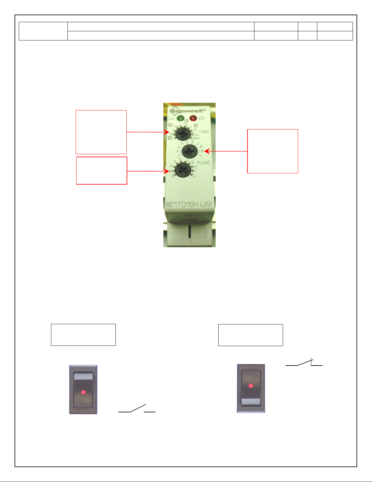
The manufacturer part number is Magnecraft 821TD10H-UNI and details can be seen at:
http://magnecraft.thomasnet.com/item/all-categories/relays-time-delay-and-sensor/pn-
2927?&plpver=10&origin=keyword&by=prod&filter=0

Procedure: Document #: Rev: Page:
SERVICE
BULLETIN 24VDC INPUT POWER MODIFICATION FOR DELAYED SHUTDOWN 9 57 1 6 of 6
REVISION HISTORY
REVISION
DESCRIPTION OF CHANGES
DATE
APPROVED
1
INITIAL RELEASE
3
A
U
G
9
KF
SEAKEEPER, INC.
P.O. BOX 999, 14528 SOUTH SOLOMONS ISLAND ROAD, SOLOMONS, MARYLAND, 2 688, U.S.A
PHONE: 41 -326-159 FAX: 41 -326-1199 E-MAIL: customerservice@seakeeper.com
Other manuals for 7000 GYRO
2
Table of contents
Other Seakeeper Marine Equipment manuals