All Data Subject to Change Without Notice 2023-0043 1S6507 Rev 7 Your Best Connection™
Anderson™ will use reasonable efforts to include accurate and up-to-date content in the assembly instruction. All product information contained in the instruction sheet
including ordering information, illustrations, specifications, and dimensions, are believed to be reliable as of the date of publishing, but is subject to change without notice.
Anderson™ makes no warranty or representation as to its accuracy. Content in the instruction sheet may contain technical inaccuracies, typographical errors and may be
changed or updated without notice. Anderson™ may also make improvements and/or changes to the products and/or to the programs described in the content at any time
without notice. Current sales drawings and specifications are available upon request.
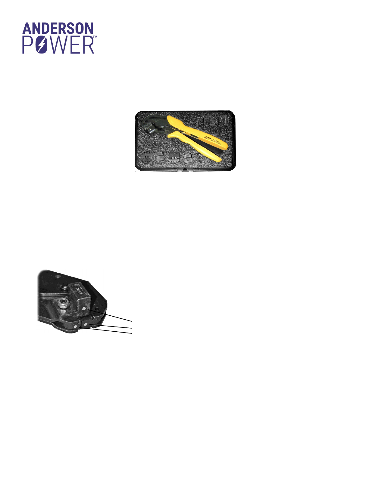
Use of tooling solutions not tested by Anderson™ can affect not only performance but also safety agency approvals.
©2023 Anderson Power Products, Inc. All rights reserved. Anderson Power™, Anderson™, the Anderson Power™ logo and Your Best Connection™ are trademarks of
Anderson Power Products, Inc.
HEADQUARTERS: Anderson Power Products®, 13 Pratts Junction Road, Sterling, MA 01564 -2305 USA T:+1 978-422-3800 F:+1 978-422-0128 • EUROPE: Anderson
Power Products® Ltd., Unit 3, Europa Court, Europa Boulevard, Westbrook, Warrington, Cheshire, WA5 7TN United Kingdom T: +44 (0) 1925 428390 F: +44 (0) 1925
520203 • GERMANY: IDEAL® Industries Germany GmbH, Esslinger Strasse 7, D – 70771 Leinfelden-Echterdingen, T: +49 (0) 711 – 997606666 • ASIA / PACIFIC:
IDEAL® Anderson Asia Pacific Ltd., Unit 922-928 Topsail Plaza, 11 On Sum Street, Shatin N.T., Hong Kong T:+(852) 2636 0836 F: +(852) 2635 9036 • INDIA: IDEAL®
INDUSTRIES India Private Limited, 229-230, SPAZEDGE, Tower B, Sector 47, Sohna Road, Gurgaon – 122018, Haryana, India T: +(91) 956 007 5905 • CHINA: IDEAL®
Anderson Technologies (Shenzhen) Ltd., Block A8 Tantou Western Industrial Park, Songgang Baoan District, Shenzhen, PR. China 518105 T: +(86) 755 2768 2118 F: +(86)
755 2768 2218 • www.ideal-Industries.in • www.andersonpower.com
Tooling
Part Number
Contact Series
Loose Piece
Only
Locator
Color Code
Die
Color Code
Wire Size
AWG (mm²)
Pullout Values
(lbf) (per UL
standard 486A)
When Properly
Crimped **
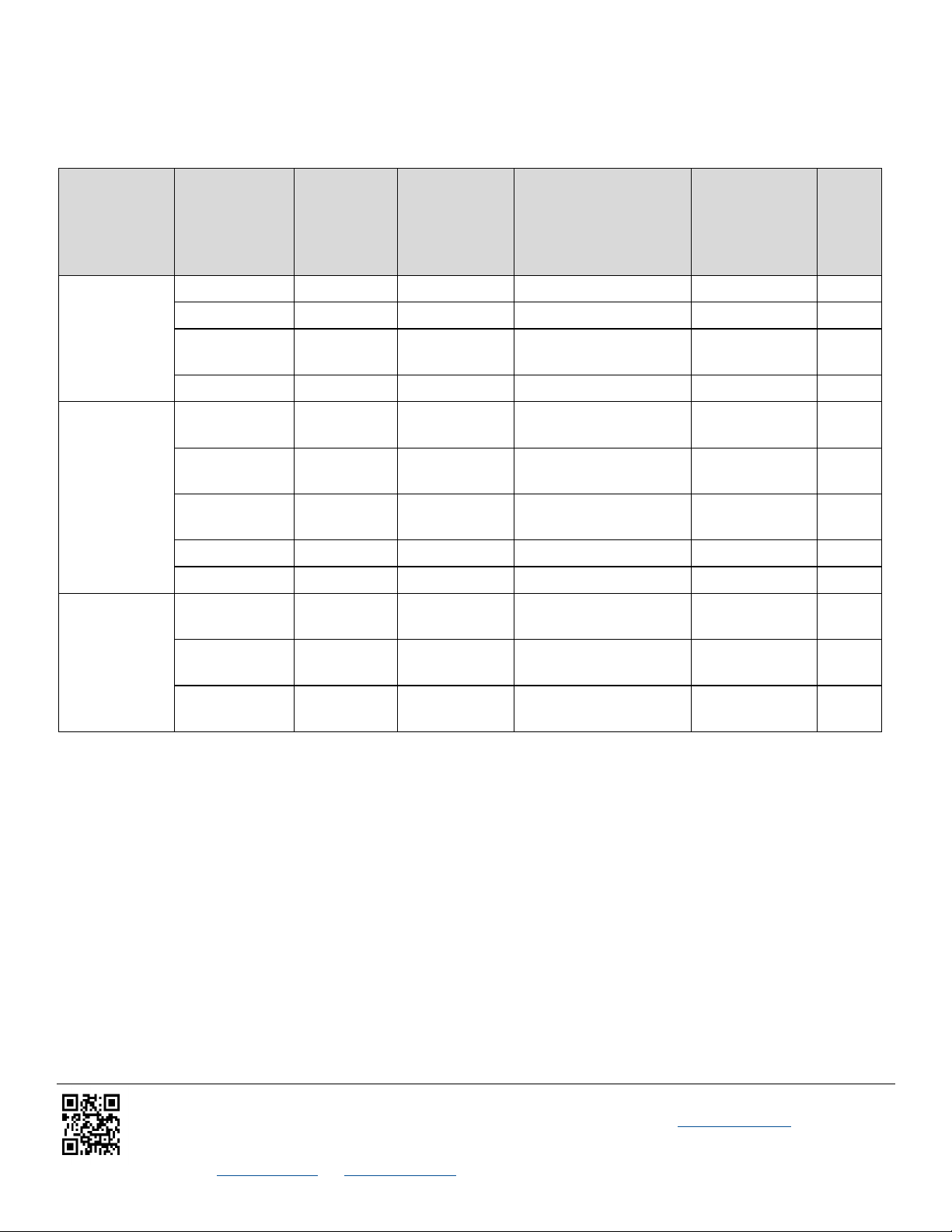
Tool
Cavity
1309G2 1331 Red Red 12 to 16 (1.3 to 3.3) 70 to 30 30
1332 Red Red 20 to 16 (0.52 to 1.3) 30 to 13 15
262G1-LPBK Red Red 16 to 20 (1.3 to 0.52) 30 to 13 15
269G2-LPBK Red Red 16 to 20 (1.3 to 0.52) 30 to 13 15
1309G3 261G1-LPBK Yellow Yellow 12 to 16 (3.3 to 1.3) 70 to 30 A
261G2-LPBK Yellow Yellow 14 to 10 K* (2.1 to 5.3) 80 to 50 B
261G2-LPBK Yellow Yellow 14 to 10 K* (2.1 to 5.3) 50 to 30 A
269G1-LPBK Yellow Yellow 16 to 12 (1.3 to 3.3) 70 to 30 A
269G3-LPBK Yellow Yellow 14 to 10 K* (2.1 to 5.3) 80 to 50 A
1309G6 200G1L-LPBK Blue Blue 14 to 10 SF* (2.1 to 6.0) 80 to 50 B
201G1H-LPBK Blue Blue 10 to 14 (5.3 to 2.1) 80 to 50 B
1830G1-LPBK Blue Blue 10 to 14 (5.3 to 2.1) 80 to 50 B
** Tool user is responsible to ensure that the crimps made conform to the quality and agency specifications.
K* is for 10 AWG class K stranded wire or smaller. For larger wires use Super Flex contacts.
SF* indicates wires with high stranding such as Super Flex.
Contact Reference Guide