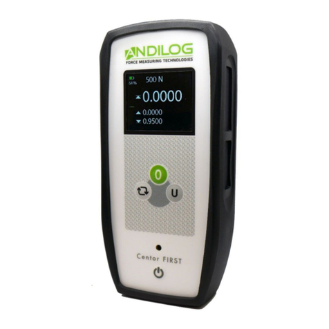
ANDILOG CENTOR FIRST User manual

Instructions Manual
CENTOR FIRST
Operating Manual
CENTOR FIRST
ANDILOG Technologies - BP62001 - 1384 Vitrolles Cedex 9 - France
Email : [email protected]om Site : www.andilog.com
Tel : +33(0)442 348 340 – Fax : +33(0)442 348 349

Instructions Manual
–
V1
CENTOR FIRST
- 1 -
I. INTRODUCTION TO THE CENTOR FIRST ............................................................................ 2
II. HANDLING.................................................................................................................... 2
1. Unpacking................................................................................................................. 2
2. Recommendation before first use................................................................................ 2
III. Operation Overview ...................................................................................................... 3
1. Charging the Batteries................................................................................................ 3
2. Low Battery Warning ................................................................................................. 3
3. Fitting Accessories ..................................................................................................... 4
4. Mounting to a Test Stand ........................................................................................... 4
IV. Turn on your Centor First ............................................................................................... 4
V. How to use your Centor First .......................................................................................... 6
1. Display of Tension/Compression.................................................................................. 6
2. Zeroing the Gauge ..................................................................................................... 6
3. Changing the Unit of Measure..................................................................................... 7
4. Max (peak) Readings / “Max” Mode............................................................................. 7
. Auto-off.................................................................................................................... 8
6. Invert Display ............................................................................................................ 8
VI. Dimensions................................................................................................................... 9
Revision
Date
Description

Instructions Manual
–
V1
CENTOR FIRST
- 2 -
I. INTROD CTION TO THE CENTOR FIRST
Thank you for choosing the CENTOR First gauge manufactured by Andilog Technologies.
This force gauge is the result of 2 years experience in force and torque measurements with new
electronic technologies offering a higher-performance and more reliable instrument.
Though it is a very comprehensive instrument, the CENTOR First force gauge is easy to use. This
instruction manual will guide you to set your first measurements.
II. HANDLING
CAUTION - Unpacking: Your CENTOR First force gauge has been supplied in its carrying case. Check
that it has not been damaged during transportation. If you have any doubt, please contact us, and
our service support will you guide you through simple checks to ensure that the gauge has not been
damaged.
1. Unpacking
The CENTOR First gauge is supplied with:
•Carrying case (according to your setup)
•Extension rod (Internal sensor only)
•Hook (Internal sensor only)
•Compression plate (Internal sensor only)
•Power plug adaptor
•Certificate of calibration
2. Recommendation before first use
a.Battery
The battery reaches its maximum capacity after several charges. This is very important! A new force
gauge has a battery that does not have its full capacity at the first power on. The force gauge will
shut down automatically if the battery is too low.
The battery life is 8 hours under a normal use. The gauge should be charged after normal use. You
should charge it every 3 weeks, to ensure a maximum life time of the batteries.
It is recommended to use the original power adaptor supplied by ANDILOG Technologies. The power
adaptor has the following specifications: 6 V, 1 A
b.Sensor
Never connect accessories (hook, plate . . .) directly to the sensor rod. se the
extension rod delivered with your instrument.

Instructions Manual
–
V1
CENTOR FIRST
- 3 -
In spite of its mechanical protection, sensor overload can damage the instrument. The instrument
stops if the capacity has been exceeded 10 times. You have to return it to ANDILOG TECHNOLOGIES
for checking.
It is important that measured values are under 90% of the sensor capacity.
c. Test Stand
The gauge can be affixed to a test stand via two M screws, which should not extend through the
back cover more than 3 mm. Please contact ANDILOG Technologies if you need more information or
if you need a fixture to mount your force gauge to a test stand.
d.Conditions
•Working Temperature: 0°C to +3 °C
•Stock Temperature: -20°C to +4 °C
•Humidity: % to 9 %
•Altitude: 3000m
III. Operation Overview
1. Charging the Batteries
Connect the AC charger to the CENTOR FIRST charger socket located at the right hand side of the
gauge next to the display and charge the batteries for 14-16 hours. Only use the adaptor/charger
supplied.
2. Low Battery Warning
A low battery symbol will blink in the display approximately two minutes before
the gauge powers down automatically.
The CENTOR FIRST can also be powered directly from the AC adapter/charger.

Instructions Manual
–
V1
CENTOR FIRST
- 4 -
3. Fitting Accessories
Affix the extension rod to the load cell probe in the
hole at the bottom of the gauge by tightening it gently
with the fingers.
Note: When fitting a grip ensure that it is screwed
finger-tight only. Excessive torque can damage the load
cell.
4. Mounting to a Test Stand
. On the rear of the gauge there are two M threaded
holes, which can be used for mounting the gauge to an
ANDILOG test stand. Each ANDILOG test stand is supplied
with a dedicated dovetailed mounting bracket and screws
for this purpose. If you wish to mount to another type of
stand, ensure that the screws used are threaded into the
gauge to a maximum depth of 0.21 inch. The final thread
is peaned but if screws are fitted beyond this depth,
damage to internal parts of the PCB may occur.
IV. Turn on your Centor First
Please note that CENTOR FIRST is measuring very low forces may not show zero if it is moved during
the self test routine. Once it is properly mounted and zeroed the reading will be stable.
As shown in Figure 1 the control panel has four keys.

Instructions Manual
–
V1
CENTOR FIRST
- 5 -
Figure 1 CENTOR FIRST control panel
To power up the gauge press the red On/OFF key: A short self test runs at power on
Then the display will show the model and capacity in Newtons.
After the self test, providing no load has been applied to the instrument, the display will show all
zeroes. This is because the gauge rezeroes itself during the self test routine.
If a force is applied via the load cell probe (hole at bottom of CENTOR FIRST), the reading on the
display will register the applied force.

Instructions Manual
–
V1
CENTOR FIRST
- 6 -
If a force of more than 20% of the maximum capacity is applied via the load cell probe (hole at
bottom of CENTOR FIRST), the display will show ‘OVERLOAD’
All the current settings are saved when the gauge is turned off and the gauge will function in the
same mode when powered up again.
V. How to use your Centor First
1. Display of Tension/Compression
Tensile forces are displayed on the CENTOR FIRST and recognized by the symbol ▲
Compressive forces are displayed on the CENTOR FIRST and recognised by the symbol ▼
Figure 2 Tension and compression displays
A load indicator bar alerts the operator to how much load has been applied to the load sensor. As the
load approaches the maximum rating of the load sensor, the indicator bar changes appearance when
above approx. 80% of the rated capacity. This warns you that steps should be taken to prevent
excessive load being applied 2.
2. Zeroing the Gauge

Instructions Manual
–
V1
CENTOR FIRST
- 7 -
During the operation of the gauge it is often necessary to zero the display – e.g. when you wish to
tare out the weight of a grip, so it does not become part of the measured reading. Press and release
the ZERO key. The display will blink momentarily as the zero operation is carried out.
3. Changing the Unit of Measure
You can choose from the following units of measure depending on the capacity of your
gauge:Newtons, kilogram-force, or pound-force. To change the display unit press and release the
key. Each successive key press will select the next available unit until the gauge returns to its original
setting. The CENTOR FIRST automatically converts readings as new units of measure are selected.
A N, Kg, Lbs will appear in the screen.
4. Max (peak) Readings / “Max” Mode
The gauge detects and stores maximum (peak) force in both compressive and tensile directions.
Press the MAX key. The display will show the letter M together with the highest tensile force
detected during the test.
Press the MAX key again. The display will show the letter M together with the highest compressive
force detected during the test.
The current load being applied to the load sensor can also be displayed pressing again the key MAX
Figure 3a Max Compression Figure 3b Max Traction

Instructions Manual
–
V1
CENTOR FIRST
- 8 -
. Auto-off
An Auto-off feature conserves battery power , the gauge powers down after 1 minutes since the
last key press.
To power down the gauge press the red key.
WARNING
If the CENTOR FIRST has suffered a serious overload condition, the load indicator bar will be partially
displayed even when no load is present. This is a warning that the load cell is damaged and you
should immediately contact your supplier to arrange repair.
Do not overload the load sensor. This will cause irreparable damage
. Forces greater than 100% of fullscale will produce an blinking display until load is released.
. Forces greater than 120% of fullscale will produce the word OVERLOAD display until load is
released.
The sensor will support 200% of fullscale without damage. In case of a permanant OVERLOAD is
displayed, consult your supplier to arange repair.
6. Invert Display
The display may be inverted or “reversed”, so that the
operator can read it more comfortably. Press and hold
the ZERO and UNIT keys This feature is remembered
after power down
Pressing again ZERO and UNIT key will place the display in
original position.

Instructions Manual
–
V1
CENTOR FIRST
- 9 -
VI. Dimensions
Table of contents
Other ANDILOG Measuring Instrument manuals
Popular Measuring Instrument manuals by other brands

Vitrek
Vitrek 4700 Operating and maintenance manual

Honeywell
Honeywell Themis alpha EI2 Operating instructions for operators and installers

Hanna Instruments
Hanna Instruments HI 93124 instruction manual

Thermo Electron
Thermo Electron Orion 920Aplus quick start guide

Forch
Forch 5380P 2 manual

Emerson
Emerson Rosemount Clarity II T56 quick start guide