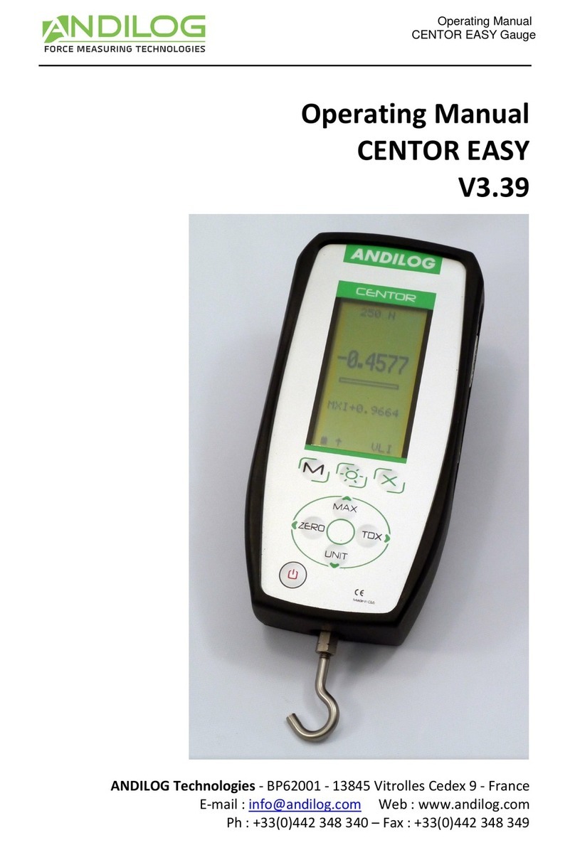
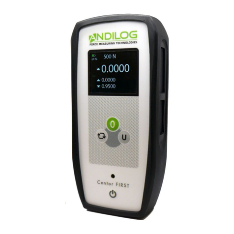
ANDILOG CENTOR EASY II User manual

Instruction manual
CENTOR EASY II
- 2 -
Contents
1. Introduction..................................................................................................................................... 4
1.1. Presentation ............................................................................................................................ 4
1.2. Recommendations before use ................................................................................................ 4
1.2.1. Battery ............................................................................................................................. 4
1.2.2. Sensor .............................................................................................................................. 4
1.2.3. Test stand ........................................................................................................................ 5
1.2.4. Test precautions .............................................................................................................. 5
1.2.5. Ambient conditions ......................................................................................................... 5
1.2.6. Warranty.......................................................................................................................... 5
2. Getting started ................................................................................................................................ 7
2.1. Battery charging ...................................................................................................................... 7
2.2. Accessories assembly .............................................................................................................. 7
2.2.1. Internal sensor force gauge............................................................................................. 7
2.2.2. External sensor force gauge type S2 or S9 ...................................................................... 7
2.2.3. TH torque gauge .............................................................................................................. 9
2.2.4. TW torque gauge ............................................................................................................. 9
2.3. Test stand mounting.............................................................................................................. 10
3. Using the Centor EASY II................................................................................................................ 11
3.1. Start-up.................................................................................................................................. 11
3.2. Switching off.......................................................................................................................... 12
3.3. Measurement screen ............................................................................................................ 13
3.3.1. Go Zero .......................................................................................................................... 14
3.3.2. Change unit of measure ................................................................................................ 15
3.3.3. Change display order..................................................................................................... 15
3.3.4. Auto-off ......................................................................................................................... 15
3.3.5. Memory backup ............................................................................................................ 15
3.4. Menu ..................................................................................................................................... 16
3.4.1. DATA menu.................................................................................................................... 16
3.4.2. SET POINTS menu .......................................................................................................... 17
3.4.3. SYSTEM menu................................................................................................................ 18
3.5. USB communication .............................................................................................................. 19

Instruction manual
CENTOR EASY II
- 3 -
4. Maintenance and repair................................................................................................................ 21
4.1. Main faults and solutions ...................................................................................................... 21
4.2. Technical data........................................................................................................................ 22

Instruction manual
CENTOR EASY II
- 4 -
1. Introduction
1.1. Presentation
Thank you for choosing CENTOR EASY II force and torque gauges from ANDILOG.
This instrument is the result of over 35 years of experience in force and torque measurement. It
incorporates the latest available technologies to deliver industrial-level performance and
measurement quality.
1.2. Recommendations before use
1.2.1. Battery
The Centor EASY II is equipped with a learning battery management component. This component
updates itself in real time according to battery wear. For the first few charge/discharge cycles, the
percentage of battery remaining may not be very accurate. This accuracy improves after a few cycles
and will be updated throughout the battery's life cycle.
Battery life is 15 hours in normal operation. The force gauge should be charged when the battery is
empty after normal use. If the force gauge is not used for a long period, it should be kept with a battery
charge of between 30 and 80% of its autonomy.
We recommend that you use the original power supply supplied by Andilog to recharge your
instrument. The power supply must have the following characteristics: micro-USB, 5V, 1A minimum.
Rechargeable batteries have a limited number of charge cycles and may need to be replaced. Battery
life and number of charge cycles vary with use and settings.
1.2.2. Sensor
Never connect accessories or fixtures (hooks, trays, etc.) directly to the load cell. Use
the extension cable supplied with your instrument.
Despite this instrument's overload protection, applying a force greater than the load
cell's capacity can damage the force gauge or torque gauge. This instrument is
equipped with an overload counter which provides information on the operating
conditions of the device.
It is important that the measured values are generally below 90% of the sensor's capacity. Constantly
operating the load cell above 90% of its capacity can lead to premature wear. When the force gauge is
used on a motorized frame, it is necessary to program the frame to stop when the force approaches
the maximum capacity of the load cell. This limit must consider that, at high speeds, a frame will not
stop immediately, and the risk of damage to the load cell is high due to the motor's inertia.

Instruction manual
CENTOR EASY II
- 5 -
1.2.3. Test stand
The force gauge or torque gauge can be fixed to a frame using M5 or 10-32 screws. The length of the
screws used must not exceed 3mm inside the instrument. Contact Andilog if you need further
information or if you require an adapter to mount the instrument on a frame.
1.2.4. Test precautions
Most of the tests carried out with instruments from the Andilog Technologies range are destructive
tests. The hazards associated with this type of testing require our instruments to be used by
experienced and trained operators. Due to the nature and use of the equipment sold by Andilog, the
purchaser's acceptance of Andilog Technologies' products constitutes acceptance of the risks and
damages that may result from the use of Andilog's instruments.
1.2.5. Ambient conditions
•Operating temperature: 0 to 35° C
•Storage temperature: -20 to 45° C
•Relative humidity: 5% to 95%, non-condensing
•Maximum operating altitude: 3,000 m
1.2.6. Warranty
Subject to the conditions below, Andilog Technologies warrants to the purchaser that it will repair or
replace at no charge new instruments sold subject to normal use and maintenance. This warranty
applies if the purchaser detects a defect in workmanship or materials within
a period of two (2) years from the date of shipment.
The conditions of application are:
•ANDILOG was notified in writing of the defect before the end of the
warranty period.
•Products are shipped to Andilog Technologies with prior agreement
from Andilog Technologies.
•All transport costs are paid by the buyer.
•The products have been used and maintained under normal
conditions of use.
Any repair or replacement carried out by the seller without the agreement of Andilog Technologies
voids the warranty.
In no event will Andilog be liable for any damages, business interruption or production stoppage arising
from the purchase, use or non-operation of our products. Even if Andilog has been informed of the
possibility of such damage.
The accuracy of our devices is guaranteed at the time of shipment at the value indicated in our
documentation or offers.

Instruction manual
CENTOR EASY II
- 6 -
If products are damaged during shipment, notify the carrier and Andilog Technologies immediately.
The warranty is void in the event of accident, misuse, or abuse.
The warranty does not cover calibration, overloaded sensors, or consumable parts such as batteries,
unless the damage is due to a material or manufacturing defect.

Instruction manual
CENTOR EASY II
- 7 -
2. Getting started
The usual functions (display force or torque, display maximum, zero and change units) can be
accessed simply by using the keys on the keypad.
2.1. Battery charging
Connect the AC adapter to the micro-USB connector on the left-hand side of your instrument. The
green LED on the front panel lights up when the battery is charging. When charging is complete, the
LED goes out.
2.2. Accessories assembly
2.2.1. Internal sensor force gauge
Attach the extension cable supplied in the case to the load cell stem at the bottom of the force gauge.
Tightening should be done by hand, without applying excessive torque. Excessive torque or the use of
pliers can damage the load cell. We recommend that you fit the accessories with the force gauge
switched on, to ensure that you do not apply a heavy load to the load cell when fitting the accessories.
2.2.2. External sensor force gauge type S2 or S9
Mounting precautions for S2 and S9 external load cell force gauges are :
•S2 and S9 force load cells are fitted with strain gauges. These are protected by white silicone.
Your accessories, screws, etc. must not come into contact with this silicone. This would prevent
measurement and risk destroying the sensor.
•Torsion, bending and shear loads are disruptive factors and should be avoided.
S2 sensor :

Instruction manual
CENTOR EASY II
- 8 -
Maximum tightening torque for mounting and accessories: 15Nm.
Mounting direction:
S9 sensor:
Maximum tightening torque for mounting and accessories:
•For load cells up to 10kN: 50Nm (M12)
•For 20kN load cells: 200Nm (M24x2)
•For 50kN load cells: 500Nm (M24x2)
Mounting direction:
The screws must not
come into contact with
the white silicone.
Strain gauge zone

Instruction manual
CENTOR EASY II
- 9 -
2.2.3. TH torque gauge
TH torque gauges are equipped with a dismantling chuck. The square used on the TH chuck is a 3/8"
square. It is retained on the side by a support screw.
Screw features:
•6 hexagon socket UNC 6-32 thread, 5/16" long
•6-pan wrench size: 1/16''.
2.2.4. TW torque gauge
TW torque gauges are fitted with a male square. The dimensions are as follows:
•15 and 60Nm: 3/8''
•150Nm: 1/2''
Measurements with the TW sensor must be taken along the axis of the square. Using an extension on
the square to change the axis of measurement will result in a false measurement.

Instruction manual
CENTOR EASY II
- 10 -
2.3. Test stand mounting
On the back of the force gauge are 2xM5 and 2x10-32 threaded holes which can be used to mount the
force gauge on an ANDILOG frame. Each ANDILOG frame is supplied with a special spacer and fixing
screws for this purpose.
If you wish to use another type of frame, check that the screws used have a maximum length of 3mm.
Although threaded holes are blind, the use of longer screws may destroy components on the
electronic board inside the instrument.

Instruction manual
CENTOR EASY II
- 11 -
3. Using the Centor EASY II
3.1. Start-up
Please note that the Centor EASY II measures very small variations in force or torque and may not
display exactly zero if moved during its self-test procedure. When correctly mounted and zeroed, the
reading remains stable.
Start-up is performed by pressing the key, a short self-test procedure displays the following screen:
After the self-test, if the unit is functional, the force gauge displays the measurement screen. It then
displays 0 N. A tare is performed when the unit starts up.
If the force applied is greater than:
•10% of maximum capacity, a warning message is displayed at start-up indicating the
percentage of force applied to the load cell. The force gauge can still be used, but we
recommend using accessories weighing less than 10% of the load cell's capacity.
•At 20% of maximum capacity, the force gauge displays a maintenance screen. At the bottom
of this screen, the force applied in % is indicated. The unit cannot be used if the start-up force
is greater than 20%. In this case, switch off the force gauge and remove the preload before
switching it on again.
For example, for a force gauge with a capacity of 500N, the force applied to the load cell must not
exceed 100N at start-up.

Instruction manual
CENTOR EASY II
- 12 -
Force applied at force gauge start-up (must be less
than 20%)
Value of the maximum force applied to the load
cell
Counter for the number of overloads applied to
the load cell
Displayed in orange if the next calibration date has
passed
Battery voltage
All settings are stored in memory when the force gauge is switched off. The force gauge will operate
with the same settings when switched back on (unit, display order).
3.2. Switching off
To switch off the Centor EASY II, press and hold the button until the instrument switches off (5
seconds).

Instruction manual
CENTOR EASY II
- 13 -
3.3. Measurement screen
Battery indicator: varies between 0% and 100% to show battery life. When the battery is new, it will
last approximately 15h in continuous use. When the battery percentage reaches 0%, the force gauge
switches off.
Capacity display: indicates the capacity of the sensor installed in the instrument, as well as the unit of
measurement.
Bar graph: The bar graph shows the operator how much force is being applied relative to the load
cell's maximum capacity. When a compressive force is applied, the bar graph fills upwards. When a
tensile force is applied, the bar graph fills in downwards.
Measurement display:
A force applied in traction will be preceded by the symbol ▼
A force applied in compression is preceded by the symbol ▲
Clockwise torque is preceded by the symbol
A counterclockwise torque will be preceded by the symbol
Example for force measurement:

Instruction manual
CENTOR EASY II
- 14 -
Example for force measurement :
The display order can be changed by pressing the
3.3.1. Go Zero
During tests, it is often necessary to reset the display to zero (e.g. to tare an accessory). Press the
green 0 key. The display shows 0.
Indicates direction of
measurement (tension or
compression). Force measured
instantaneously
Maximum pull from tare
Maximum compression from
tare
Indicates direction of
measurement (clockwise or
counterclockwise). Torque
measured instantaneously
Maximum clockwise
Maximum counter-clockwise

Instruction manual
CENTOR EASY II
- 15 -
3.3.2. Change unit of measure
You can choose from the following units:
•Force gauge: N, KN, kg, lb, oz, g and daN.
•Torque meter: Nm, mNm, kg.cm, lbin, lbft, ozin.
Some units may not be available, depending on the load cell capacity. For example, for a 150Nm
capacity load cell, it is not possible to measure in mNm.
To change the unit display, press the U key. Each successive press will select the next unit until you
return to the starting unit. The Centor EASY II will automatically convert the display and capacity to
the new chosen unit and display the corresponding unit symbol.
The number of decimal places displayed changes according to the unit selected. It corresponds to
1/10,000 of the sensor capacity.
3.3.3. Change display order
The torque meter detects and stores the maximum tension and compression values. Press the
key. The display order of the various values will shift upwards. The top line will then move to the
bottom. Each time you press this key, the display changes. Centor EASY II remembers the display
order when it is switched off.
3.3.4. Auto-off
Automatic shutdown saves battery charge. The force gauge is automatically switched off after 15
minutes without pressing any key.
3.3.5. Memory backup
A long press on this key activates or deactivates the maximum memory save function.
When this function is activated, the save counter is displayed at the bottom right of the
screen. Up to 500 values can be saved.
A short press on this key saves the maximum value in memory, which has a blue arrow
in front of it. Each press increments the save counter at the bottom of the screen. Access to the values
and setting of the saved value is via the menu.

Instruction manual
CENTOR EASY II
- 16 -
3.4. Menu
The different menus:
•DATA: Access to stored maximum values
•SET POINTS: limit setting
•SYSTEM: access to force gauge information
The keyboard is used to navigate the menu:
•Up and down arrows: change lines
•Right arrow: to enter a menu
3.4.1. DATA menu
The Centor Easy II can store the maximum measured
value in memory. It can store up to 500 values. Each
value is stored in the following format:
Measurement # Value Date Time
The saved value is indicated by the blue arrow at the
top of the screen:
•Upwards, maximum traction
•Downward, maximum compression
•To the right, clockwise
•To the left, anticlockwise
Exit Menu
Menu access

Instruction manual
CENTOR EASY II
- 17 -
To change the type of value to be saved, move to the "Peak" line, then press the right arrow. A message
appears, asking if you wish to delete all values in memory. Warning: changing the type of value to be
saved systematically deletes all values in memory.
If you wish to clear the memory without changing direction, press and hold the left arrow.
3.4.2. SET POINTS menu
This menu allows you to set thresholds on the force
gauge. A sound can be emitted when thresholds are
exceeded, and the color of the measurement display
can be changed according to thresholds.
Mode: selects whether the threshold is in tension or
compression, clockwise (CW) or counterclockwise
(CCW).
Value 1 and Value 2: threshold values in the unit of
measurement.
Color, BIP: changes the color of measurements if the
threshold is exceeded and/or emits a sound.
How it works:
•If Value 1 and Value 2 are 0, the threshold function is deactivated.
•If Value 1 has a value and Value 2 is 0. Only one threshold is activated. In this case, if the
maximum of the chosen direction exceeds the value in Value 1, the force gauge beeps and/or
the digits turn orange.
•If Value 1 and Value 2 have a value, then there are 2 thresholds set. In this case, if the maximum
force exceeds Value 1, the Centor Easy II emits a beep and/or the values turn green. If the
maximum force exceeds Value 2, the values change to orange.
Example of use:
1. I've got a 500N force gauge, and I want to shoot a sample. If it breaks above 100N, my parts
are good (displayed in green). The settings to be applied are as follows:
Mode: Traction
Value 1: 100N
Value 2: 500N
Color: Yes
Beep: No
2. I have a 100N force gauge and I want to compress a sample. If the force exceeds 50N, my parts
are bad (orange display and beep). The settings to be applied are as follows:

Instruction manual
CENTOR EASY II
- 18 -
Mode: Comp.
Value 1: 50N
Value 2: 0.00N
Color: Yes
Beep: Yes
3.4.3. SYSTEM menu
Includes all force gauge configuration information:
First screen:
•Serial number
•Force gauge capacity
•Load at force gauge start-up in %
of capacity
•Next calibration date
Second screen:
•Internal software version
•Sensor factory offset setting
•Traction gains
•Compression gain
•Battery voltage

Instruction manual
CENTOR EASY II
- 19 -
Third screen:
•Today's date
•Time
These values can be modified using the
keyboard arrows. Press the right arrow to
start editing.
3.5. USB communication
The Centor Easy II is equipped with a USB connection for communication with a computer. It can be
connected to our Caligraph software to send continuous data. It can also be connected to a
HyperTerminal, LabVIEW or any other data acquisition system. It is then seen as a COM port.
The Centor Easy II adapts its communication parameters automatically and is able to respond
automatically to communication speeds of up to 921600 baud. Characters are sent and received in
ASCII.
Available controls :
•Start transmission of instantaneous measurements.
oOrdering: 1
oAnswer in the form: "Unit value Unit value...".
•Stop transmission of instantaneous measurements.
oOrdering: 2
•Request to send file of saved maximums (DATA menu contents)
oOrder: T
oAnswer in the form:
"XXX Y/Z Val Unit Date Time \n
....
XXX Y/Z Val Unit Date Time \n "
Where:

Instruction manual
CENTOR EASY II
- 20 -
XXX represents the measurement number
Y/Z represents the mouse counter (Y: animal counter / Z: trial number)
•Request to send back-up file of saved maximums.
oOrder: R
oAnswer in the form:
"XXX Y/Z Val Unit Date Time \n
....
XXX Y/Z Val Unit Date Time \n "
Where:
XXX represents the measurement number
Y/Z represents the mouse counter (Y: animal counter / Z: trial number)
•Device identification
oOrdering: ?
oDevice model query.
oAnswer: E
•Tare
oOrder: Z
Receipt of a command, other than a tare or measurement start request, stops the transmission of
instantaneous measurements.
Instantaneous measurements are sent when the device is not on the main measurement page. It
restarts when you return to the main page (unless a command to the contrary is received).
All data sent is signed. Tensile forces are considered positive, compressive forces negative.
Table of contents
Other ANDILOG Measuring Instrument manuals
Popular Measuring Instrument manuals by other brands

Ruskin
Ruskin EFAMS Installation and maintenance manual

DH Instruments
DH Instruments PG7607 - 2008 Operation and maintenance manual

LOVATO ELECTRIC
LOVATO ELECTRIC DME D110T1 instruction manual

Tekon
Tekon 560 user manual

Shot-Scope
Shot-Scope V2 user guide

Ametek
Ametek SPECTRO SPECTROCHECK Original operating instructions