Apeks Regulator User manual

®
Regulator Owner’s Manual
DOC/0258/USA ISSUE 1

Copyright Notice
This owner’s manual is copyrighted, all rights reserved. It may not, in
whole or in part, be copied, photocopied, reproduced, translated or
reduced to any electronic medium or machine readable form without
prior consent in writing from Apeks.
©2005 Apeks
Regulator Owner’s Manual
P/N AP5310AA
Warnings, Cautions and Notes
Pay special attention to information provided in warnings, cautions and
notes, that is accompanied by these symbols:
AWARNING indicates a procedure or situation that, if not
avoided, could result in serious injury or death to the user.
ACAUTION indicates any situation or technique that could
cause damage to the product, and could subsequently result in
injury to the user.
ANOTE is used to emphasize important points, tips, and
reminders.
WARNING: This manual provides essential instructions for
the proper setup, inspection, use, and care of your new
regulator. Because Apeks regulators utilize patented
technology, it is very important to take the time to read
these instructions in order to understand and fully enjoy
the features that are unique to your specific model.
Improper use of your regulator could result in serious
injury or death.

3
Contents
General Precautions & Warnings …………………………………4
Introduction ……………………………………………………………5
Using Enriched Air Nitrox (EAN) ……………………………………6
Overview of Features …………………………………………………8
Second Stage Configuration…………………………………………8
Diver Changeable Exhaust System (DCE) ………………………9
External Second Stage Adjustments ………………………………11
Integrated Venturi System …………………………………11
Inhalation Resistance Control Knob ………………………………12
Egress Second Stage ………………………………………………13
First Stage Environmental Protection ……………………………14
Second Stage Cold Water Protection ……………………………14
Preparation and Setup ………………………………………………15
Hose Attachment ……………………………………………………15
Attaching the First Stage to the Cylinder Valve (Yoke) …………16
Attaching the First Stage to the Cylinder Valve (DIN) …………18
DIN to Yoke Converter ……………………………………………19
Diving with Your Regulator ……………………………………… 20
Pre-Dive Inspection Checklist: ……………………………………20
During the Dive ………………………………………………………21
Diving In Cold Water ………………………………………………22
After the Dive ………………………………………………………… 24
Removal of the Regulator from the Cylinder Valve (Yoke) ……24
Removal of the Regulator from the Cylinder Valve (DIN) ………24
Care & Maintenance ………………………………………………25
Dealer Service & Repair ……………………………………………27
Warranty Information ……………………………………………… 28
Limited Lifetime Warranty …………………………………………28
Restrictions …………………………………………………………29
Returning Your Regulator for Service ……………………………30
ServiceRecord ……………………………………………………… 31

4
General Precautions & Warnings
■Before using this regulator, you must receive instruction and
certification in SCUBA diving from a recognized training agency (or
any U.S. Military or government operated diving school). Use of
SCUBA equipment by uncertified or untrained persons is
dangerous and can result in injury or death.
■This regulator is not configured for commercial use with surface
supplied air.
■Always pressurize the regulator gradually by opening the cylinder
valve SLOWLY.
■NEVER apply any type of lubricant to any part of the regulator or
cylinder valve.
■DO NOT apply any type of aerosol spray to the regulator. Doing so
may cause permanent damage to certain plastic components,
including the second stage housing.
■Factory prescribed service for this regulator must be performed at
least once annually by a factory trained Apeks service technician
who is employed by an authorized dealer. Disassembly, repair, or
first stage adjustment must not be attempted by persons who are
not factory trained and authorized by Apeks.
■DO NOT leave a cylinder standing unsecured with the regulator
attached to the valve. Doing so may cause permanent damage to
the regulator and cylinder valve if the cylinder falls over.
■DO NOT carry the regulator by the first stage when it is connected
to a cylinder. Always carry the cylinder by the cylinder valve or an
attached carrying device.
■When diving in cold water (below 50°F, or 10°C), you must have
received training and certification in the techniques of cold water
diving from a recognized training agency.

5
INTRODUCTION
Congratulations—and thank you—for choosing Apeks. All Apeks
regulators have been designed and manufactured with pride,
according to standards which meet or surpass all requirements for the
BS EN ISO 9001 quality control system.
Your Apeks regulator is covered by Apeks’ Limited Lifetime Warranty
against defects in materials or workmanship. This warranty is only
extended to the original purchaser, however, and is not transferable.
For more information, be sure to read the warranty section of this
manual, and remember to save your sales receipts. Copies of these
receipts must be presented whenever obtaining warranty service.
Perhaps more than any other piece of diving equipment you will own,
your regulator’s function and performance relies greatly on the care
and maintenance it will receive, in addition to regularly scheduled
dealer service. Before you dive with your new Apeks regulator, it is
therefore important to read this manual in its entirety to become
familiar with its features, as well as the correct procedures for setup,
pre-dive inspection and post-dive maintenance.
Please read on to learn how you can obtain the maximum enjoyment
from your regulator, and maintain its like-new performance for many
years to come.
WARNING: Improper use or misuse of SCUBA equipment
may result in serious injury or death. Read and understand
this owner’s manual completely before diving with your
Apeks regulator.
6
USING ENRICHED AIR NITROX (EAN)
WARNING: This section of your owner’s manual contains
important information regarding the use of your equipment
with enriched air (EAN/Nitrox). Do not attempt to use this
product with enriched air until you have read and understand
this section of the manual. To do otherwise increases your
risk of injury or death.
WARNING: Obtain an EAN (Nitrox) Certification. In order to
enjoy the special benefits that EAN/nitrox can provide, it is
extremely important to obtain special training from a
nationally recognized training agency in addition to that
which is provided for openwater scuba.
Your Apeks regulator has been prepared for use with Enriched Air
Nitrox (EAN) where the percentage of oxygen in the EAN does not
exceed 40%. This is possible because each regulator is built to a high
standard of cleanliness using EAN compatible components and
lubricants. In addition, each regulator design has passed stringent
adiabatic compression testing to ensure its safety and compatibility
with increased percentages of oxygen.
If it is your intention to use your new Apeks regulator with EAN (O2not
to exceed 40%), it is imperative that you maintain the internal
cleanliness of the regulator (see section on Care and Maintenance). If
it is your intent to use the regulator interchangeably with breathing air,
the breathing air should be oxygen-compatible or “hyperfiltered”
whereas the condensed hydrocarbons do not exceed 0.1 mg/m3. Your
local authorized Apeks dealer can help you determine whether the
breathing air that they provide meets this criterion.
Standard compressed breathing air, often referred to as Grade E in
the United States, does not necessarily meet this criterion. Grade E
breathing air may contain a certain level of hydrocarbons, including
traces of compressor oils that while not considered harmful to breathe,
can pose a risk in the presence of elevated oxygen content.
7
Passing hydrocarbons through a valve and regulator creates a
cumulative effect where the hydrocarbons build up over time along the
internal passageways of the equipment. When these hydrocarbons
come in contact with high-pressure oxygen enriched air, they can pose
a very real hazard that can lead to combustion.
Therefore, if a regulator has had use with Grade E breathing air, it
should be returned to an authorized Apeks dealer for overhaul service
including hydrocarbon cleaning, prior to being put back into nitrox
service.
Although second stage components are not exposed to high pressure
EAN, Apeks recommends that the same cleaning procedures be
followed for the complete regulator. This prevents the possibility of
cross contamination and guarantees the cleanliness of the entire
regulator.
NOTE: Apeks offers additional models of regulators that are
designed and manufactured for use with enriched air nitrox where
the percentage of oxygen exceeds 40%. For information about
these models, consult your authorized Apeks dealer.
8
OVERVIEW OF FEATURES
The Apeks family of regulators consists of different models which
satisfy a wide range of diving interests; from entry level sport diving, to
advanced diving in more demanding and extreme conditions. By now,
your authorized dealer has already explained to you the specific
features that your particular model offers, and you have made your
purchase after comparing the benefits of these features to your
personal diving needs and interests. Be sure to review this section to
learn more about your model’s features and how to obtain the
maximum benefit from using them. The XTX range offers two features
unique to XTX. The option for either left or right hand hose
configuration and the Diver Changeable Exhaust system (DCE).
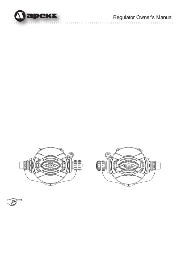
Second Stage Hose Configuration
Apeks XTX regulator range can be dedicated to either left or right
handed use in conjunction with the RVS system (see page 11). The
hose routing can be altered from right hand to left or from left hand to
right by your Authorized Apeks Dealer. This is an extremely useful
feature offering much greater flexibility for personal kit configuration.
Right Hand Left Hand
NOTE: This conversion must only be performed by a factory
trained Authorized Apeks Service Technician who is employed by
an Authorized Dealer. Contact your Authorized Apeks Dealer for
further information on this feature. Disassembly, adjustment or
repair must not be attempted by persons who are not factory
trained and authorized by Apeks.
9
Diver Changeable Exhaust system (DCE)
The Diver Changeable Exhaust (DCE) offers the choice of either a
compact lightweight system or a longer exhaust diffuser. DCE can be
configured to prevent virtually any bubble interference from obscuring
the diver’s view.
The exhaust diffusers can be easily and very quickly changed by
sliding and locking the preferred set into place. Divers can now
configure their own regulator exhaust diffusers for individual dive
conditions or requirements.
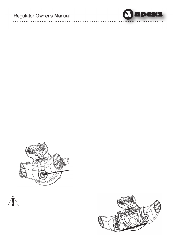
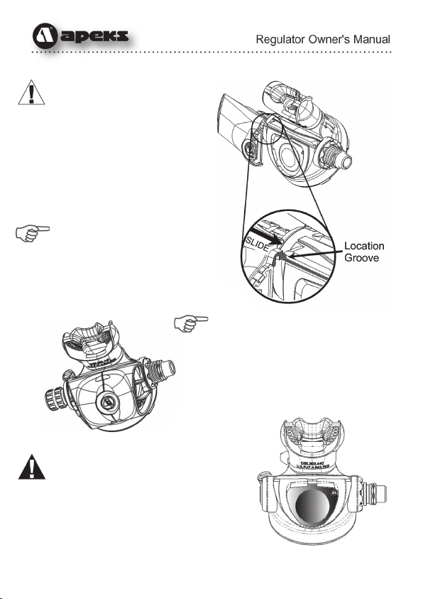
By pressing the securing button in the centre of the exhaust diffuser
and at the same time sliding the diffusers apart, they can be removed
quickly and easily.
To attach an alternative set of exhaust diffusers, align the slide
locations as shown and slide each side into place, taking care that the
exhaust diffusers are located securely. When the two diffusers meet
squeeze them together until an audible click is heard from the
retaining button.
1. First gently press the button located
in the center of the exhaust diffuser.
CAUTION! Do not use any tools
to aid the removal of the
exhaust diffusers.
2. Then slide both exhaust diffusers
apart, while keeping the button
depressed.
PRESS HERE
10
CAUTION! Ensure location
grooves are free from dirt
and debris.
3. Refitting the exhaust diffusers
is carried out by sliding ONE
diffuser at a time onto the
case, once both diffusers are
located on the case, squeeze
the two diffusers together until
you hear an audible “click”.
NOTE: The removal and
refitting of the small exhaust
diffusers is carried out in
exactly the same way as the
large exhaust diffusers.
NOTE: If the exhaust diffusers do
not securely clip together then
they may become detached and
lost. (If required, exhaust
diffusers may be purchased
separately).
WARNING: Do not attempt to use
tools to remove or attach the
exhaust diffusers. After the removal
of the exhaust diffusers care must
be taken to prevent damage to the
exhaust valve. Do not attempt to
poke, pull or touch the exhaust
valve or surrounding area with any
tools. If damage to this part or Shaded area indicates exhaust
valve and surrounding area.
11
surrounding area occurs then this could cause your
regulator to leak, causing serious malfunction or even
personal injury. Care must be taken when securing
alternative sets of diffusers, do not apply excessive force as
damage may occur to the diffusers, exhaust valve or
surrounding area.
External Second Stage Adjustments
External adjustment features offer many advantages, including the
ability to adjust your second stage regulator’s sensitivity as your
diving conditions change. This can allow you to maintain peak
performance throughout every dive, or to desensitize your regulator’s
opening effort at times when you are not breathing from it.
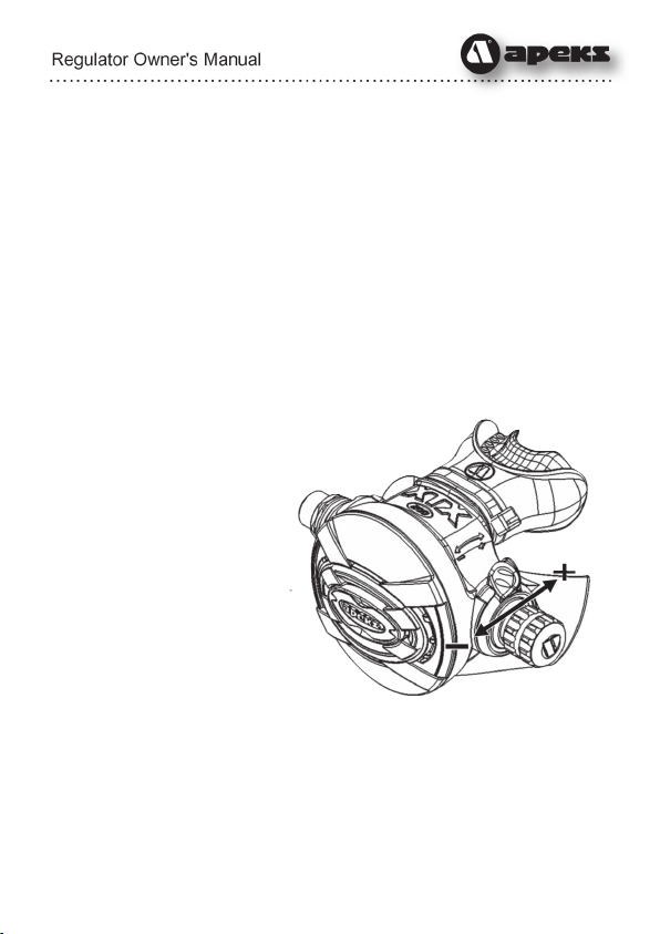
Integrated Venturi System
Apeks second stages are equipped with a
unique Integrated Venturi
System (IVS) control switch
or Reversible Venturi
System (RVS) switch,
located on the opposite side
to the hose connection of
the second stage, that
controls the venturi assist to
reduce sensitivity to freeflow at
the surface and provide
maximum airflow at depth.
While diving set the switch to plus (+) to
achieve maximum venturi assistance for easier breathing.
To prevent the second stage from free-flowing, set the IVS/RVS to the
MIN(–) setting whenever the regulator is out of your mouth.

12
Inhalation Resistance Control Knob
Some second stage models are equipped with an additional
adjustment, which controls inhalation resistance.
This control knob, located beside the
IVS/RVS switch, adjusts the amount of
effort required to start the air flow at
the beginning of the
inhalation cycle. As it is
turned “in” (clockwise),
the opening effort will
increase. This will make
the second stage less
sensitive to sudden
changes in ambient
pressure. Turning the knob
“out” (counter-clockwise) will
decrease the opening effort to
make breathing easier.
This adjustment is particularly useful at deeper depths, or in variable
conditions that affect the opening effort of the second stage, such as
strong currents or while using a diver propulsion vehicle (DPV). You
can use the inhalation control knob to tune your regulator to maintain
its peak performance throughout the course of your dive, or you can
leave it set in its mid-range position and dive with it as you would any
non-adjustable second stage.
For more information on using these adjustments, refer to the section
titled, Diving With Your Regulator, on page 20.
13
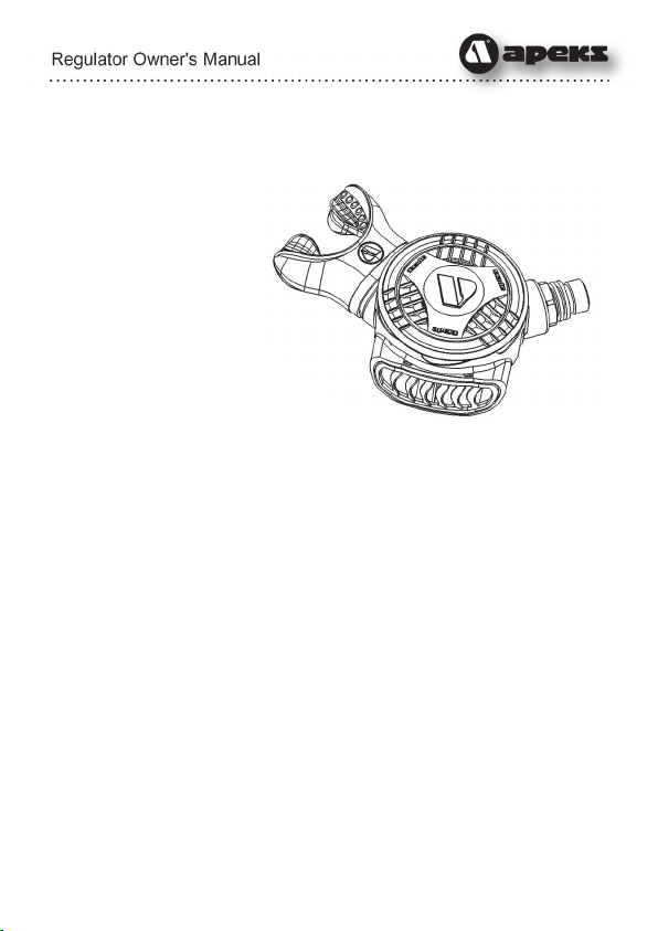
Egress Second Stage
The Egress is a low
profile second stage
suitable for use in all
diving conditions, and
can be used either way
up due to its side
exhaust and hose layout.
Therefore the diver can
use the second stage
with the hose routed from
either the left or right
depending on personal
preference and setup requirements.
The Egress second stage is primarily
aimed for use as an alternative air source
second stage although can still be used successfully as a primary
second stage. The Egress also incorporates the patented thermo-
dynamic heat exchanger technology which makes it suitable for diving
in water temperatures below 10ºC, see page 22
14
DIN to Yoke Converter
First Stage Environmental Protection
For diving in contaminated or cold
water conditions, some Apeks first
stages feature a unique “DRY”
environmental sealing system
which completely eliminates the
need for messy silicone oil or
grease filling. An external
diaphragm seals the ambient
chamber from the surrounding sea
water, while a specially designed
piston transfers ambient water
pressure to the internal diaphragm.
This helps to prevent ice from
forming inside the ambient
chamber, and also extends the life of the first stage internal
diaphragm. It is important to remember, however, that this
environmental protection will not completely prevent the second stage
from icing or freezing.
SSecond Stage Cold Water Protection
With the exception of the XTX20, AT20 & T20, Apeks second stages
incorporate a thermo-dynamic heat exchanger at the second stage
hose fitting. This patented (Patent No. U.S. Pat. 5,265,596) feature is
designed to draw in the surrounding water temperature, thereby
warming the valve mechanism and greatly reducing the possibility of
second stage freeze-up.
For important information about diving in cold water, refer to the
section titled, Diving in Cold Water, on page 22.
15
PREPARATION AND SETUP
Hose Attachment
Apeks recommends that you take your regulator to your authorized
dealer for the installation of any accessory items, including
instrumentation, medium pressure (MP) quick disconnect hoses, and
alternative air source second stages. Your dealer can also answer any
questions you may have pertaining to the information in this manual. If
it is not possible to return your regulator and accessories to your
Apeks Authorized Dealer, you may install the accessories yourself
carefully performing the steps in the following procedure.
WARNING: DO NOT connect medium pressure hoses (inflator
hoses and second stage hoses) to high pressure (HP) ports.
This will cause medium pressure hoses to burst when
pressurized, which can result in serious injury. High pressure
ports are identified by the letters ‘HP’ on your regulator and
are mainly used for instrumentation and air integrated
computers.
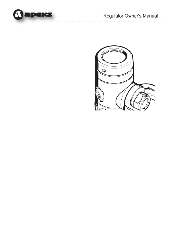
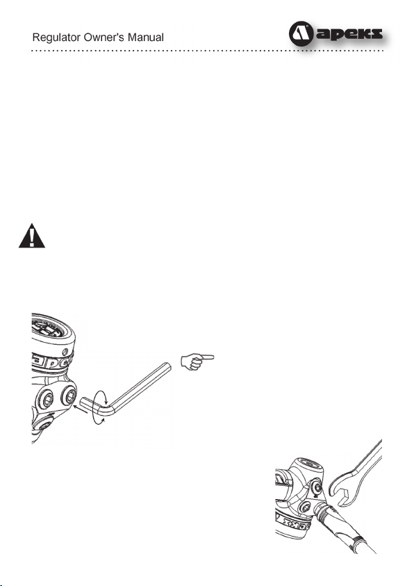
1. Remove the port blanking plug from your first stage
regulator using a 5mm Allen key.
NOTE: Care must be taken
when using a spanner/wrench
when tightening the hose
connections. The spanner can
score and damage the chrome
plating finish of first stage body
around the port area.
2. Ensure the O-ring is present and in good
condition on the hose to be fitted. Screw the
threaded end of the hose into the port making
sure that the thread is screwed in square to the
port. Tighten to 46 kg/cm (40 lbs/in) using an
appropriate sized spanner.

16
1. Check the second stage IVS/RVS control switch to ensure that it is
set to the “MIN” (–) position prior to connecting your regulator to
the tank.
2. If present, gently turn the inhalation control knob “in” (clockwise),
only until it stops. Do not apply
excessive pressure.
3. If you are using a cylinder with
a yoke connection valve,
check the cylinder valve O-ring
is fitted and not worn or
damaged. If you are using a
high pressure cylinder with a
DIN connection valve, remove
the protector cap from the first
stage to inspect the sealing
O-ring of the DIN connector. If
the sealing O-ring is damaged
or worn, replace it before
mounting the regulator on the
cylinder valve.
Attaching the First Stage to a
Cylinder Valve (Yoke Connection)
WARNING: OPEN VALVES SLOWLY TO AVOID OVER-
PRESSURIZATION. When pressurizing your SCUBA system,
be sure to open the cylinder valve slowly to minimize the
generation of heat. Failure to do so, with Enriched Air Nitrox
(EAN) present, increases the risk of combustion that can lead
to serious injury or death.
It is considered safe practice, especially when using EAN, to open the
cylinder valve slowly and let the first stage pressurize slowly. Rapid
pressurization causes adiabatic compression of the breathing gas,
which generates heat inside the first stage. Heat, along with elevated
percentages of oxygen and an ignition source (from contamination)
are the ingredients that can cause combustion. This is why it is

17
necessary to keep the interior of the regulator clean and the
percentage of oxygen below 40% along with the slow opening of the
cylinder valve (for regulators over 40% oxygen please see page 6).
To attach a yoke-style first stage to the cylinder valve, follow these
steps:
1. Partially unscrew the yoke screw of the first stage regulator so
that the dust cap can be removed from the air inlet.
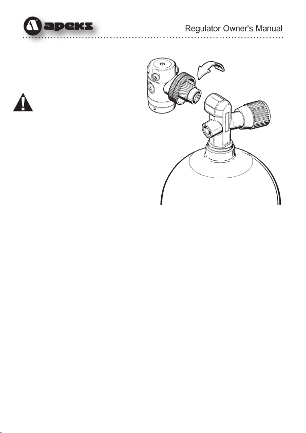
2. With the cylinder valve facing away from you, release a small
amount of air from the cylinder by turning the hand-wheel counter-
clockwise to open the valve only slightly. When air is heard exiting,
immediately close the valve. This will clear any moisture or debris
that may be inside the cylinder valve outlet opening. Check the O-
ring is still in place.
3. Place the first stage regulator over the cylinder valve so that the
inlet fitting aligns with the O-ring of the cylinder valve, and the LP
hose of the primary second stage will be routed over the desired
shoulder. While holding the first stage in place, turn the yoke
screw clockwise. Ensure that the yoke screw mates into the small
dimple on the backside of the cylinder valve, and tighten finger-
tight only - do not over tighten.
4. If a submersible pressure gauge is attached to the first stage,
ensure that the gauge is facing away from you. Pressurize the
regulator by slowly turning the cylinder valve handwheel counter-
clockwise. Continue to turn the valve handwheel counter-
clockwise until it is fully open, and then turn it back 1/2turn.
5. Listen near the first stage to check for any leakage. If leakage is
detected, immerse the first stage and cylinder valve while
pressurized to determine the source.
6. If leakage has been detected, follow the procedure for removing
the regulator from the cylinder valve on page 20. If air was leaking
between the first stage and cylinder valve, replace or re-seat the
cylinder valve O-ring as needed and repeat the above procedure.
If leakage persists, return the system to an authorized dealer.
18
Attaching the First
Stage to a Cylinder
Valve (DIN)
WARNING: OPEN VALVES
SLOWLY TO AVOID OVER-
PRESSURIZATION. When
pressurizing your SCUBA system, be
sure to open the cylinder valve slowly
to minimise the generation of heat.
Failure to do so, with Enriched Air
Nitrox (EAN) present, increases
the risk of combustion that can
lead to serious injury or death.
It is considered safe practice,
especially when using EAN, to
open the cylinder valve slowly and let the first stage pressurize slowly.
Rapid pressurization causes adiabatic compression of the breathing
gas, which generates heat inside the first stage. Heat, along with
elevated percentages of oxygen and an ignition source (from
contamination) are the ingredients that can cause combustion. This is
why it is necessary to keep the interior of the regulator clean and the
percentage of oxygen below 40% along with the slow opening of the
valve.
To attach a DIN-style first stage to the cylinder valve, follow these
steps:
1. Remove the protector cap from the cylinder valve, if fitted. With
the cylinder valve facing away from you, release a small amount of
air from the cylinder by turning the handwheel counter-clockwise
to open the valve slightly. When air is heard exiting, immediately
close the valve. This will clear any moisture or debris that may be
inside the threaded cylinder valve opening.
2. Position the first stage near the cylinder valve so that the LP hose
of the primary second stage will be routed over the desired
shoulder. Thread the first stage DIN connector into the cylinder
19
valve and tighten the handwheel by hand until it is lightly snug.
DO NOT use tools to tighten.
3. If a submersible pressure gauge is attached to the first stage,
ensure that the gauge is facing away from you. Pressurize the
regulator by slowly opening the cylinder valve handwheel.
Continue to turn the cylinder valve handwheel until fully open, and
then back 1/2turn.
4. Listen near the first stage to check for any leakage. If leakage is
detected, immerse the first stage while pressurized to determine
the source.
5. If leakage has been detected, follow the procedure for removing
the regulator from the cylinder valve on page 24. If air was leaking
between the first stage and cylinder valve, replace or re-seat the
cylinder valve O-ring as needed and repeat the above procedure.
If leakage persists, return the cylinder and regulator to an
authorized dealer.
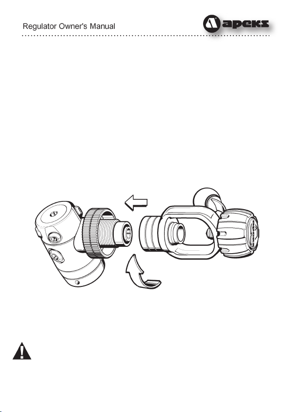
DIN to Yoke Converter
For regulators which may be
used back and forth between Yoke and DIN connections, Apeks offers
a convenient DIN to Yoke converter. First, obtain factory prescribed
installation of the DIN connector through an authorized dealer. Then,
simply attach the converter to connect your regulator to a yoke valve.
WARNING: Adaptors from yoke 1st stage to a DIN cylinder
valve must never be used. This would allow a greater working
pressure to be used than the yoke connector is designed to
take.
Second Stage Cold Water Protection

20
DIVING WITH YOUR REGULATOR
Before each use, it is important to perform a complete pre-dive
inspection of your regulator. NEVER dive with a regulator that shows
signs of damage or unsatisfactory performance until it has received
complete inspection and service from an authorized dealer.
Pre-Dive Inspection Checklist:
1. Carefully inspect all hoses at their fittings to ensure they are
securely connected into their respective ports on the first stage.
Inspect the length of each hose to ensure that the hoses are not
blistered, cut, or otherwise damaged. If hose protectors are
present, slide the protectors back to expose the hose fittings, and
inspect the hoses as described above.
2. Visually inspect both the first and second stage regulators for any
signs of external damage.
3. Environmentally sealed first stages only: Closely inspect the
external sealing diaphragm for any signs of damage or
deterioration that may cause leakage. Check to ensure that the
retainer which holds the external diaphragm in place is tightly
secured.
WARNING: If the external diaphragm shows any signs of
damage or neglect, DO NOT attempt to dive with the regulator
until it has received factory prescribed service from an
authorized dealer. The regulator’s performance may be
compromised, and first stage freeze-up could occur in cold
water conditions.
4. Connect the first stage regulator to a fully charged SCUBA
cylinder. (For mounting instructions, read the Setup section on
pages 15-19.) SLOWLY open the cylinder valve to pressurize the
regulator. Continue turning the valve counter-clockwise until it
stops, and then back 1⁄2turn. This is to ensure that the valve is
completely open.
5. If present, turn the inhalation control knob completely “out”
(counter-clockwise), and then back “in” (clockwise) until the
Table of contents
Other Apeks Diving Instrument manuals

Apeks
Apeks WTX User manual

Apeks
Apeks TX Series User manual

Apeks
Apeks ThermiQ Dry Advanced User manual

Apeks
Apeks ATX 200 User manual

Apeks
Apeks WTX-D User manual

Apeks
Apeks Quantum User manual

Apeks
Apeks XL4 SECOND STAGE User manual

Apeks
Apeks wtx series User manual

Apeks
Apeks wtx series User manual

Apeks
Apeks Black Ice User manual

Apeks
Apeks 388300 User manual

Apeks
Apeks XTX200 User manual

Apeks
Apeks WTX INFLATOR User manual

Apeks
Apeks ThermiQ Dry Advanced User manual

Apeks
Apeks MTX-R User manual

Apeks
Apeks wtx series User manual

Apeks
Apeks Black Ice Twin Cylinder Kit User manual

Apeks
Apeks NS158000 User manual

Apeks
Apeks 427106 User manual

Apeks
Apeks BLACK SAPPHIRE User manual


