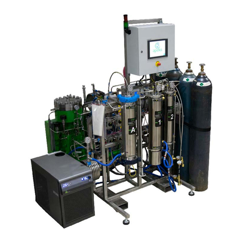
Apeks THE FORCE 2-STAGE User manual

Updated 04/23/2019 ©Apeks, LLC 2019
THE FORCE™2-STAGE 5000PSI
BOTANICAL OIL EXTRACTION SYSTEM
OPERATION MANUAL
WARNING
FAILURE TO FOLLOW THE SET UP AND OPERATION PROCEDURE
PROVIDED IN WITHIN THIS MANUAL MAY VOID THE EXTRACTION
SYSTEM’S WARRANTY
Apeks Supercritical
150 Commerce Blvd.
Johnstown OH 43031
740-809-1160
service@apekssupercritical.com
www.apekssupercritical.com
Scan this QR code to get the
most recent version of the
operating instructions.

The Force™ 2-Stage Operation Manual
2
Revision Date 4/23/2019
Table of Contents
Content Page #
1. Critical Safety Overview...............................................................................................................................5
2. System Overview.........................................................................................................................................6
2.1. Diaphragm System Overview................................................................................................................8
2.1.1. Diaphragm Compressor........................................................................................................8
2.1.2. Extractor Vessel Stand .......................................................................................................10
2.1.3. Separation Vessel/Control Stand........................................................................................12
2.1.4. Bottle Connections..............................................................................................................14
2.1.5. Extractor Chiller/Temperature Control Chiller......................................................................14
2.1.6. Separator Chiller/Regenerative Chiller................................................................................14
2.1.7. Miscellaneous/Multi-Area Parts...........................................................................................14
2.2. Automation Overview..........................................................................................................................15
2.2.1. Logo Screen.......................................................................................................................15
2.2.2. Home/Main Screen.............................................................................................................15
2.2.3. Cycle Parameter Screen.....................................................................................................16
2.2.4. Valve Control Screen..........................................................................................................16
2.2.5. Manual Screen ...................................................................................................................17
2.2.6. Maintenance Screen...........................................................................................................17
2.2.7. Message Screen.................................................................................................................18
2.2.8. Code Entry Screen ............................................................................................................19
2.2.9. I/O (Input/Output) Screens..................................................................................................19
2.2.10. Alarm History Screen .........................................................................................................24
2.2.11. Pop Up Screens .................................................................................................................24
2.3. Running Modes...................................................................................................................................26
2.3.1. Single Extractor..................................................................................................................26
2.3.2. Dual Extractor.....................................................................................................................26
2.3.3. Continuous Batch ...............................................................................................................27
2.4. Manual Screen Buttons ......................................................................................................................27
2.4.1. Service Separator Mode/Leave Service Separator Mode....................................................27
2.4.2. Change CO2Bottles............................................................................................................27
2.4.3. Oil Pressure Lost Reset......................................................................................................27
2.4.4. Diaphragm Rupture Reset..................................................................................................27
2.4.5. Evacuate ............................................................................................................................27
2.4.6. Open Extractor Vessel........................................................................................................27
2.4.7. Recover CO2 .................................................................................................................................................................................................27
2.4.8. Water Flow Lost Reset .......................................................................................................27
2.4.9. Switch Separators...............................................................................................................27
2.4.10. Start/Stop Extractor Chiller .................................................................................................27
2.4.11. Start/Stop Separator Chiller................................................................................................27
2.4.12. Lamp Test ..........................................................................................................................27
2.4.13. Start/Stop Compressor Prime.............................................................................................27
2.4.14. Fill Separator Bank 2 Water................................................................................................27
3. System Operation......................................................................................................................................28
3.1. Before the Cycle.................................................................................................................................28
3.1.1. Loading and Closing Extractors..........................................................................................28
3.1.2. Prepping and Securing Separators.....................................................................................29
3.1.3. Evacuating System.............................................................................................................30
3.2. Starting the Cycle ...............................................................................................................................30
3.2.1. The Cycle Parameters Screen............................................................................................30
3.2.2. The Main Screen ................................................................................................................30

The Force™ 2-Stage Operation Manual
3
Revision Date 4/23/2019
3.2.3. System Response on Startup.............................................................................................31
3.3. Recommended Operating Parameters................................................................................................31
3.3.1. Subcritical...........................................................................................................................31
3.3.2. Supercritical........................................................................................................................31
3.4. During the Cycle.................................................................................................................................31
3.4.1. Service Separator/Cleaning out Separator that is offline.....................................................31
3.4.2. Cleaning Out Extractor in Continuous Batch Mode.............................................................32
3.4.3. Changing Bottles................................................................................................................32
3.5. After the Cycle ...................................................................................................................................32
3.5.1. System Response on Shutdown.........................................................................................32
3.5.2. Operator Maintenance........................................................................................................33
4. System Preventive Maintenance ...............................................................................................................34
4.1. Extraction System Maintenance (Extractor and Separator Stands).....................................................34
4.2. Diaphragm Compressor Maintenance.................................................................................................34
4.3. Chiller Maintenance............................................................................................................................34
5. Troubleshooting ........................................................................................................................................36
5.1. System Messages ..............................................................................................................................36
5.1.1. Leak Detect Switch Tripped................................................................................................36
5.1.2. E-stop Reset ......................................................................................................................36
5.1.3. Payment due by end of month ...........................................................................................36
5.1.4. Check orifice size. Elevated separator pressure detected ..................................................36
5.1.5. Diaphragm pump pressure switch tripped ..........................................................................36
5.1.6. Monthly code entry required ..............................................................................................36
5.1.7. Pump outlet pressure high..................................................................................................36
5.1.8. Separator pressure has risen .............................................................................................36
5.1.9. Low bottle detected at Start Up...........................................................................................36
5.1.10. Machine is in bottle change mode ......................................................................................36
5.1.11. Cycle complete or terminated but vessel(s) still pressurized ..............................................36
5.1.12. Recovery complete ...........................................................................................................36
5.1.13. Check/Replace Bottle ........................................................................................................36
5.1.14. Extractor Pressure > 2000psi twice in ten minutes .............................................................36
5.1.15. Extractor Pressure not equalizing ......................................................................................36
5.1.16. Recovering due to low system pressure ............................................................................36
5.1.17. Recovery has begun ..........................................................................................................36
5.1.18. CO2Low Bottle pressure ...................................................................................................36
5.1.19. Transition to (BA/AB) but Ext (A/B) not ready ....................................................................36
5.1.20. Sep pressure test failed......................................................................................................36
5.2. System Alarms ...................................................................................................................................36
5.2.1. Air PSI High/Low Alarm .....................................................................................................36
5.2.2. Chiller 1 Fault/Warning Alarm ............................................................................................36
5.2.3. Chiller 2 Fault/Warning Alarm ............................................................................................36
5.2.4. CO2 Storage PSI High/Low Alarm ......................................................................................37
5.2.5. CO2Supply PSI High/Low Alarm ........................................................................................37
5.2.6. Code Needed Alarm ..........................................................................................................37
5.2.7. Diaphragm Compressor Ambient Temperature Alarm .......................................................37
5.2.8. Diaphragm Compressor Outlet PSI High Alarm .................................................................37
5.2.9. Diaphragm Compressor Suction PSI High Alarm ...............................................................37
5.2.10. Diaphragm Compressor Suction PSI Low Alarm ................................................................37
5.2.11. Diaphragm Rupture Shutdown Alarm .................................................................................37
5.2.12. E-Stop Alarm .....................................................................................................................37

The Force™ 2-Stage Operation Manual
4
Revision Date 4/23/2019
5.2.13. Extractor Not Equalizing Alarm ..........................................................................................37
5.2.14. Extractor Water Flow Lost Alarm .......................................................................................37
5.2.15. Extractor Ambient Temperature Alarm ...............................................................................37
5.2.16. Extractor (Vessel A/B, Top/Bottom) PSI High Alarm...........................................................37
5.2.17. Extractor (A/B) Vessel Temperature Alarm ........................................................................37
5.2.18. Filter (1B/2B) PSI Drop Fault/Warning ...............................................................................37
5.2.19. Low System CO2Pressure Alarm ......................................................................................37
5.2.20. Oil Pressure Lost Alarm .....................................................................................................38
5.2.21. Pressure Test Fail Alarm ...................................................................................................38
5.2.22. Pump PSI High During Recovery Alarm .............................................................................38
5.2.23. Pump Motor Auxiliary Fault Alarm ......................................................................................38
5.2.24. Pump Motor Overload Alarm .............................................................................................38
5.2.25. Separator Pressure Creep Alarm .......................................................................................38
5.2.26. Separator Water Flow Lost Alarm ......................................................................................38
5.2.27. Separator (1B/2B) Vessel PSI High Alarm .........................................................................38
5.2.28. Separator (1B/2B) Vessel Temperature Alarm ...................................................................38
5.2.29. Separator Ambient Temperature Alarm .............................................................................38
5.2.30. Service Separator Mode Extractor PSI High Alarm ............................................................38
5.2.31. Valve Fault Alarm ..............................................................................................................38
5.3. Other Symptoms ................................................................................................................................38
5.3.1. Vessel not Pressurizing .....................................................................................................38
5.3.2. High Extractor Pressure and Low Separator Pressure........................................................38
5.3.3. High Separator Pressure and Low Extractor Pressure........................................................38
6. References ...........................................................................................................................................39
7. Appendices ...........................................................................................................................................40
7.1. A – Belt Tension Testing/Adjustment..................................................................................................40
7.2. B – Diaphragm Pump Priming.............................................................................................................41
7.3. C – Check Valve Cleaning..................................................................................................................42
7.4. D – Piping and Instrumentation Diagram.............................................................................................45
7.5. E – CO2 Phase Diagram .....................................................................................................................48
7.6. F – Pre-Training Checklist...................................................................................................................49
7.7. G – Electrical Screw Torque Requirement .........................................................................................52
7.8. H – Apeks Automatic Machine Fault Troubleshooting Guide ..............................................................53

The Force™ 2-Stage Operation Manual
5
Revision Date 4/23/2019
1. Critical Safety Overview
Throughout these instructions, this symbol is used to indicate that the instructions are critically
important to your safety and the safety of your system. Failure to follow the instructions as written
can result in a rapid release of high pressure CO2potentially causing equipment or personnel
damage.
WARNING
Subcritical and Supercritical CO2systems operate under high pressure. Operators must be fully trained and
familiar with the system. Failure to operate the system can result in equipment damage and/or bodily injury.
WARNING
Subcritical and Supercritical CO2systems use large amounts of CO2during operation. Ensure that system is
installed in a well-ventilated area to prevent buildup of CO2which can cause asphyxiation. Use of a CO2monitor
is strongly recommended.
WARNING
Opening a vessel under pressure can result in a rapid release of pressure and ejection of the material inside the
vessel. DO NOT ATTEMPT TO OPEN A VESSEL UNDER PRESSURE! Always make sure a vent path for the
vessel is opened and the corresponding pressure gage reads zero prior to loosening the vessel hammer unions
or closure bolts.
WARNING
Subcritical and Supercritical CO2systems are designed to operate indoors. Extreme temperatures (below 60°F
and above 80°F) will negatively impact the functionality of the system. The environmental temperature range is
for the system, chiller, pump and CO2bottles.
WARNING
Only use Propylene Glycol and distilled water in the chiller and cooling system. Never use Deionized Water in
the chiller or cooling system.
WARNING
Extraction system components can weigh in excess of 2000 lbs and need to be moved carefully. Never attempt
to move system pieces without the proper equipment, failure to do so could result in serious injury or death.
WARNING
Always wear safety glasses when operating and servicing the system.
Table of contents
Other Apeks Industrial Equipment manuals


