Apeks Prospiant BAMBINO User manual
Version 2, May 2021
Updated 5/4/2021 © Apeks LLC, 2021
THE BAMBINO® 2000psi and
THE TRANSFORMER® 2000psi
Botanical Oil Extraction System
Operation Manual
WARNING
FAILURE TO FOLLOW THE SET UP AND OPERATION PROCEDURE PROVIDED IN WITHIN
THIS MANUAL MAY VOID THE EXTRACTION SYSTEM’S WARRANTY
Apeks Supercritical, now known as Prospiant
150 Commerce Blvd.
Johnstown OH 43031
740 809-1160 opt 2
service@prospiant.com
www.apekssupercritical.com
Scan this QR code to get the most recent
version of the operating instructions.

The Bambino® and The Transformer® Operation Manual
Updated 5/4/2021 2 © Apeks LLC, 2019
Table of Contents
Page
1. Critical Safety Overview ................................................................................................................................................... 3
2. System Operation ............................................................................................................................................................ 4
2.1. Automation Overview ........................................................................................................................................... 4
2.2. Screen Shots .......................................................................................................................................................... 6
2.3. Pre-Cleaning .......................................................................................................................................................... 9
2.4. Depressurizing System After Recovery ................................................................................................................. 9
2.5. Remaining Oil from Separator #1 ........................................................................................................................ 10
2.6. Closing Separation Vessels .................................................................................................................................. 12
2.7. Maintenance After Every Run ............................................................................................................................. 12
2.8. Opening Extraction Vessel .................................................................................................................................. 15
2.9. Removing Spent Material from Extraction Vessel .............................................................................................. 16
2.10. Loading Botanical Material .................................................................................................................................. 16
2.11. Closing Extraction Vessel ..................................................................................................................................... 16
2.12. Chiller Start Up .................................................................................................................................................... 18
2.13. Evacuating System (Pulling Vacuum) .................................................................................................................. 17
2.14. Conducting an Extraction .................................................................................................................................... 17
2.15. Recommended Operating Parameters ............................................................................................................... 19
3. System Maintenance ..................................................................................................................................................... 20
3.1. Extraction System Maintenance ......................................................................................................................... 20
3.2. Diaphragm Compressor Maintenance ................................................................................................................ 21
3.3. Chiller Maintenance ............................................................................................................................................ 21
4. Troubleshooting ............................................................................................................................................................ 22
4.1. Ice on Separator or Collection Cup ..................................................................................................................... 22
4.2. Low Extractor Pressure ....................................................................................................................................... 22
4.3. Extractor Overpressure/Service Separator ......................................................................................................... 22
4.4. Low Separator Pressure ..................................................................................................................................... .23
4.5. Wrong Orifice Size ............................................................................................................................................... 23
4.6. Differing Separator Pressure ............................................................................................................................... 23
4.7. Oil Carryover to Separator #2 or Filter Housing .................................................................................................. 23
5. References ..................................................................................................................................................................... 24
6. Appendices: ................................................................................................................................................................... 25
6.1. A. Belt Tension Testing/Adjustment ................................................................................................................... 25
6.2. B: Diaphragm Pump Priming Instruction ............................................................................................................ 28
6.3. C: Check Valve Cleaning ...................................................................................................................................... 29
6.4. C: Piping and Instrumentation Diagram .............................................................................................................. 32
6.5. D: CO2Phase Diagram ......................................................................................................................................... 34
6.6. E: Pre-Training Checklist ...................................................................................................................................... 35
6.7. F: Electrical Screw Torque Requirements ........................................................................................................... 37

The Bambino® and The Transformer® Operation Manual
Updated 5/4/2021 3 © Apeks LLC, 2019
1. Critical Safety Overview
Throughout these instructions, this symbol is used to indicate that the instructions are critically important
to your safety and the safety of your system. Failure to follow the instructions as written can result in a
rapid release of high pressure CO2potentially causing equipment or personnel damage.
WARNING
Subcritical and Supercritical CO2systems operate under high pressure. Operators must be fully trained and familiar with
the system. Failure to operate the system can result in equipment damage and/or bodily injury.
WARNING
Subcritical and Supercritical CO2systems use large amounts of CO2during operation. Ensure that system is installed in a
well-ventilated area to prevent buildup of CO2which can cause asphyxiation. Use of a CO2monitor is strongly
recommended.
WARNING
Opening a vessel under pressure can result in a rapid release of pressure and ejection of the material inside the vessel.
DO NOT ATTEMPT TO OPEN A VESSEL UNDER PRESSURE! Always make sure a vent path for the vessel is opened and the
corresponding pressure gauge reads zero prior to loosening the vessel hammer unions.
WARNING
Subcritical and Supercritical CO2systems are designed to operate indoors. Extreme temperatures (below 60°F and above
80°F) will negatively impact the functionality of the system. The environmental temperature range is for the system,
chiller, pump and CO2bottles.
WARNING
Only use Propylene Glycol and distilled water in the chiller and cooling system. Never use Deionized Water in the chiller
or cooling system.
WARNING
Extraction system components can weigh in excess of 2000 lbs and need to be moved carefully. Never attempt to move
system pieces without the proper equipment, failure to do so could result in serious injury or death.
WARNING
Always wear safety glasses when operating and servicing the system.
The Bambino® and The Transformer® Operation Manual
Updated 5/4/2021 4 © Apeks LLC, 2019
2. System Operation
The following operating instructions are for The Bambino® i.2000psi and The Transformer® 2000psi CO2 based Botanical
Oil Extraction systems. Instructions manuals for the Thermo-Fisher chiller and Diaphragm Compressor are supplied
separately. Failure to follow the instructions provided below may void the warranty of the extraction system and its
components.
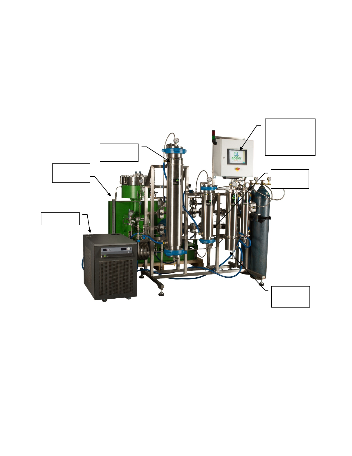
2.1. The Transformer® System Overview
Figure 1. System Components of The Transformer®
2.2. Automation Overview
2.2.1. The Human Machine Interface (HMI) is a 10″color touch screen. Almost all of the inputs, outputs and
human/machine interactions are managed through the HMI.
2.2.2. The HMI has two functions: 1) to provide information and 2) to accept inputs from the operator.
Description of some of the interaction is here:
2.2.2.1. If a display value or message is colored orange, an operator must take action before moving
forward.
Chiller
Separation
Vessels
Collection
Cup
Extraction
Vessels
Diaphragm
Pump
Controller/HMI
(Human
Machine
Interface)
The Bambino® and The Transformer® Operation Manual
Updated 5/4/2021 5 © Apeks LLC, 2019
2.2.2.1.1. Orange indicates that an operator activity is required before the Start button can be
depressed. Messages highlighted orange are indicative of a scheduled maintenance interval
being reached.
2.2.2.2. Red messages indicate that a component of the system has either failed to reach the minimum
operating pressures or temperatures, or that it exceeded the programmed operating limits. Red
messages are typically reserved for alarms that could potentially shut down the machine if the
condition causing the alarm is not returned to normal.
2.2.2.2.1. Red messages may require user acknowledgement or may simply disappear when an
abnormal condition returns to normal parameters. If a button appears, user intervention
will be required.
2.2.2.3. Yellow messages will typically be displayed on a button that has to be pressed to acknowledge that
the operator has read the message before it disappears.
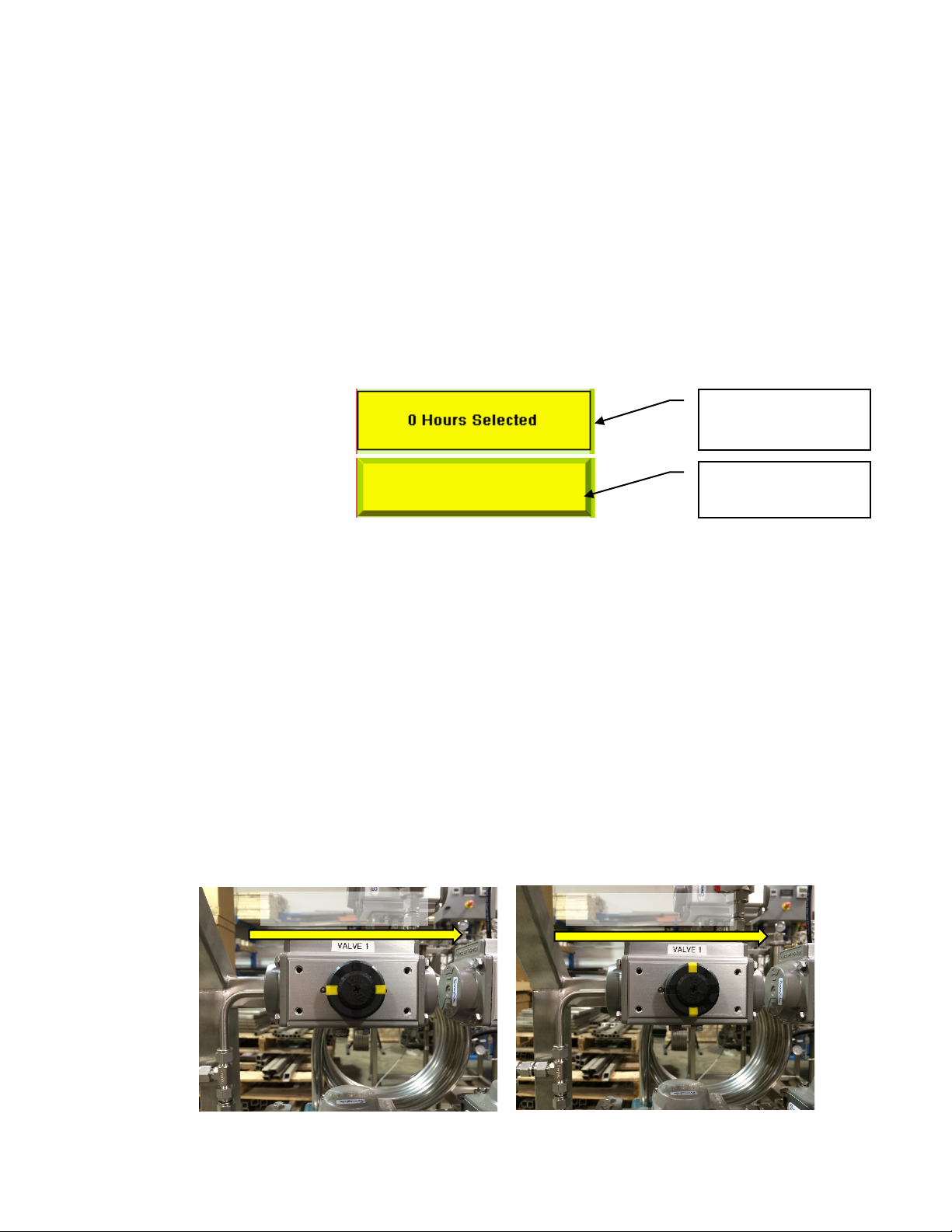
2.2.3. Any variables or messages that need to be (or can be) controlled by the operator are graphically raised
to illustrate that the “message” is a button. An example of the different graphical representations is
shown in Figure 2.
Figure 2. Indicator vs. Button
2.2.4. The controller has safety interlocks programmed into it. These safety interlocks prevent unsafe
operations from occurring by monitoring the system parameters and by removing unsafe action/input
control buttons from the HMI. When buttons appear to be missing from the home screen, it is because
the system is performing an operation that would be unsafe in combination with the missing
button/action.
2.2.5. The HMI will provide message pop ups (in yellow boxes) to instruct the operator what steps are
required next in order in to complete any action selected. Most message pop ups are also
acknowledgement buttons that must be pressed before any further action can be taken.
2.2.6. The primary operating valves on the Apeks system are air actuated valves controlled by the systems
controller. In the event of an air compressor failure or a power failure all air actuated valves will return
to their normal resting state. Valves 0 and 17B will be normally open and all others will be closed.
2.2.7. Each air actuated valve has an indicator on the top to inform the operator which valves are open and
which ones are closed. The indicator lines correspond with the flow direction. Figure 3 illustrates both
and open and closed valve. Note that it does not matter which way the air actuator is oriented, rather
the direction of CO2flow is important.
Title/Output Display
with solid edge
Input Button with
Chamfered edge
CO
2
Flow Direction
CO2Flow Direction
Figure 3. a) Valve 1 in the open position, b) Valve 1 in the closed position
The Bambino® and The Transformer® Operation Manual
Updated 5/4/2021 6 © Apeks LLC, 2019
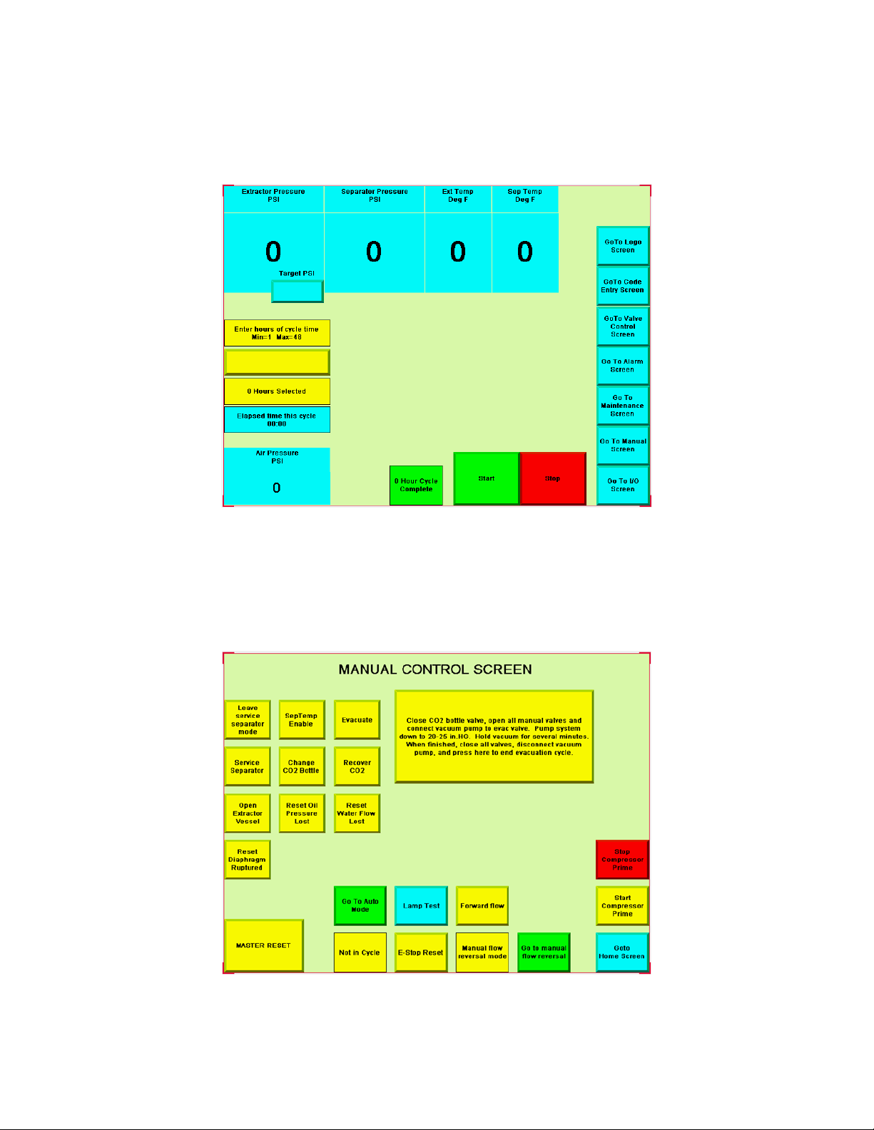
2.3. Screen Shots
2.3.1. Home Screen
The home screen is where all pressures, temperatures, run times, and access to other screens are
located. This is where you will enter your parameters and start your extractions.
Figure 4. Home Screen single system
2.3.2. Manual Screen
The manual screen is used quite often, and is where to go to perform any operations other than normal
operation such as clearing a clogged orifice, recovering CO2before the entered run time is complete,
opening the extractor vessel, or changing a CO2bottle.
Figure 5. Manual Screen
The Bambino® and The Transformer® Operation Manual
Updated 5/4/2021 7 © Apeks LLC, 2019
On the manual screen, there's a button to switch between automatic flow reversal and manual flow
reversal. When in manual flow reversal mode, the operator can press a button to switch the flow
direction at any time during the run.
When in automatic flow reversal, the machine will only change flow direction when a new extraction is
started, meaning that forward flow at the beginning will remain forward flow until the next run. The
next run will be reverse flow and will remain reverse flow for the entire run.
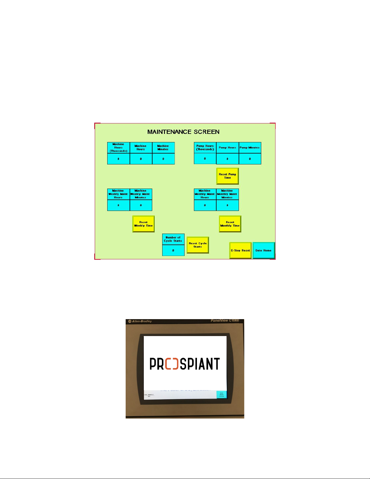
2.3.3. Maintenance Screen
The Maintenance screen is where you will go to monitor run times on your system and pump for
scheduling and maintenance.
Figure 6. Maintenance Screen
2.3.4. Logo Screen
The Logo Screen shows the system software revision number which is located in the bottom left of this
screen. The reason for the logo screen is to hide any potentially secret parameters on the home screen.
Figure 7. Logo Screen
The Bambino® and The Transformer® Operation Manual
Updated 5/4/2021 8 © Apeks LLC, 2019
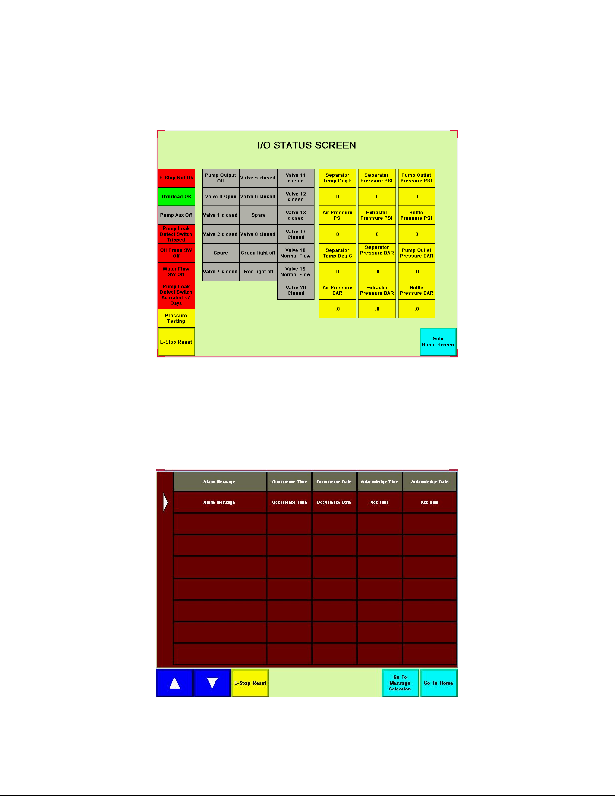
2.3.5. I/O (Input/Output) Status Screen
The I/O screen is used for troubleshooting. On this screen, you can monitor which valves are supposed
to be open and closed, if the pump is on or off, and if the light on top of the machine is green or red.
There are also indicators showing thermocouple raw input data as well as air and CO2pressures in PSI.
Figure 8. I/O Status Screen
2.3.6. Alarm Screen
The Alarm screen is used for troubleshooting, and where navigation to text messaging screen is located.
When the system faults for any reason, it is recorded on the alarm screen. A lot of times the fault you
see on the home screen may have been caused by a series of faults. By looking at the alarm screen you
can see all the previous faults in the order that they occurred.
Figure 9. Alarm Screen

The Bambino® and The Transformer® Operation Manual
Updated 5/4/2021 9 © Apeks LLC, 2019
2.4. Pre-Cleaning
2.4.1. The Apeks system is constructed from 304 and 316 stainless steel and can be cleaned with any cleaner
that is compatible with both stainless steel and your extracted product. Alcohol (200 proof) works well
for most applications.
2.4.2. The system should be cleaned to the appropriate level (determined by your application and
corresponding regulations) prior to processing each batch of botanical material.
2.4.2.1. Apeks takes great care to clean all systems prior to shipping, however, it is the user’s responsibility
to ensure that the system meets their required level of cleanliness before processing material.
2.5. Depressurizing System after Recovery
2.5.1. After completion of recovery, Valve 4 (4A and 4B for dual vessel) will open to relieve residual extractor
pressure. A yellow acknowledge button will appear in the home screen.
2.5.2. Follow directions in order:
2.5.2.1. Close (turn clockwise) CO2Bottle(s).
2.5.2.2. Open Valve 10 to relieve separator pressure.
2.5.2.3. Press acknowledge box, this will relieve the pressure in the CO2bottle lines and the rest of the
system.
2.5.3. Open all manual valves.
2.5.4. Turn off the chiller/heater.
2.5.5. NOTE: any time the diaphragm pump stops the system will automatically vent CO2from valve 0 in
order to relieve stress on the diaphragm head.
2.5.6. If system was stopped unexpectedly and system needs recovered proceed to the “Manual Screen” to
recover CO2and then follow the steps above.
The Bambino® and The Transformer® Operation Manual
Updated 5/4/2021 10 © Apeks LLC, 2019
2.6. Removing Oil from Separator #1
WARNING
DO NOT ATTEMPT TO OPEN A VESSEL UNDER PRESSURE! Always make sure a vent path
for the vessel is opened and the corresponding pressure gauge(s) reads zero prior to
loosening the vessel closure bolts.
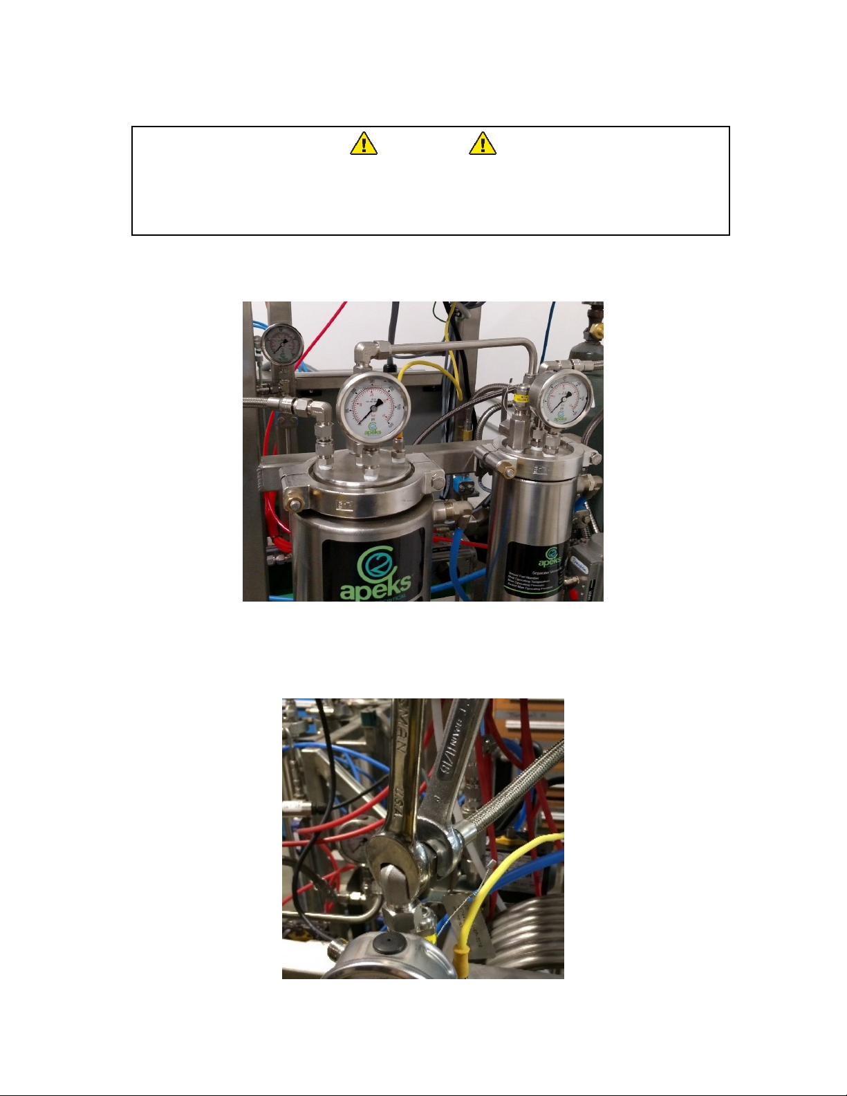
2.6.1. Ensure Valve 10 is open.
2.6.2. Ensure that the all three gauges on separator vessels (shown in Figure 10) and separator pressure on
the home screen reads zero.
Figure 10. Gauges to Check when Removing Sanitary Clamps
2.6.3. Remove the flexible metal line and connection pipe from the top of the separators. Use two wrenches
to prevent the bending tubes or NPT fittings from loosening in the separator cap (see Figure 11).
Figure 11.Illustration of using two wrenches to remove lines
1
3
2
The Bambino® and The Transformer® Operation Manual
Updated 5/4/2021 11 © Apeks LLC, 2019
2.6.4. Remove the yellow wire connected to the Separator #1 thermocouple.
2.6.5. Remove the white vent tube attached to the pressure relief.
2.6.6. Use the 5/8″ ratchet wrench to remove the high pressure sanitary clamps from the top of Separator
#1.
2.6.7. Remove the cap from the top of separator.
2.6.8. Collect any available oil from the separator cap.
2.6.9. Use alcohol to clean the caps and orifice tube.
2.6.10. Use the supplied round squeegee or hard plastic scraper to push any residual oil from the sides of the
Separator #1 down to the bottom and in the collector cup.
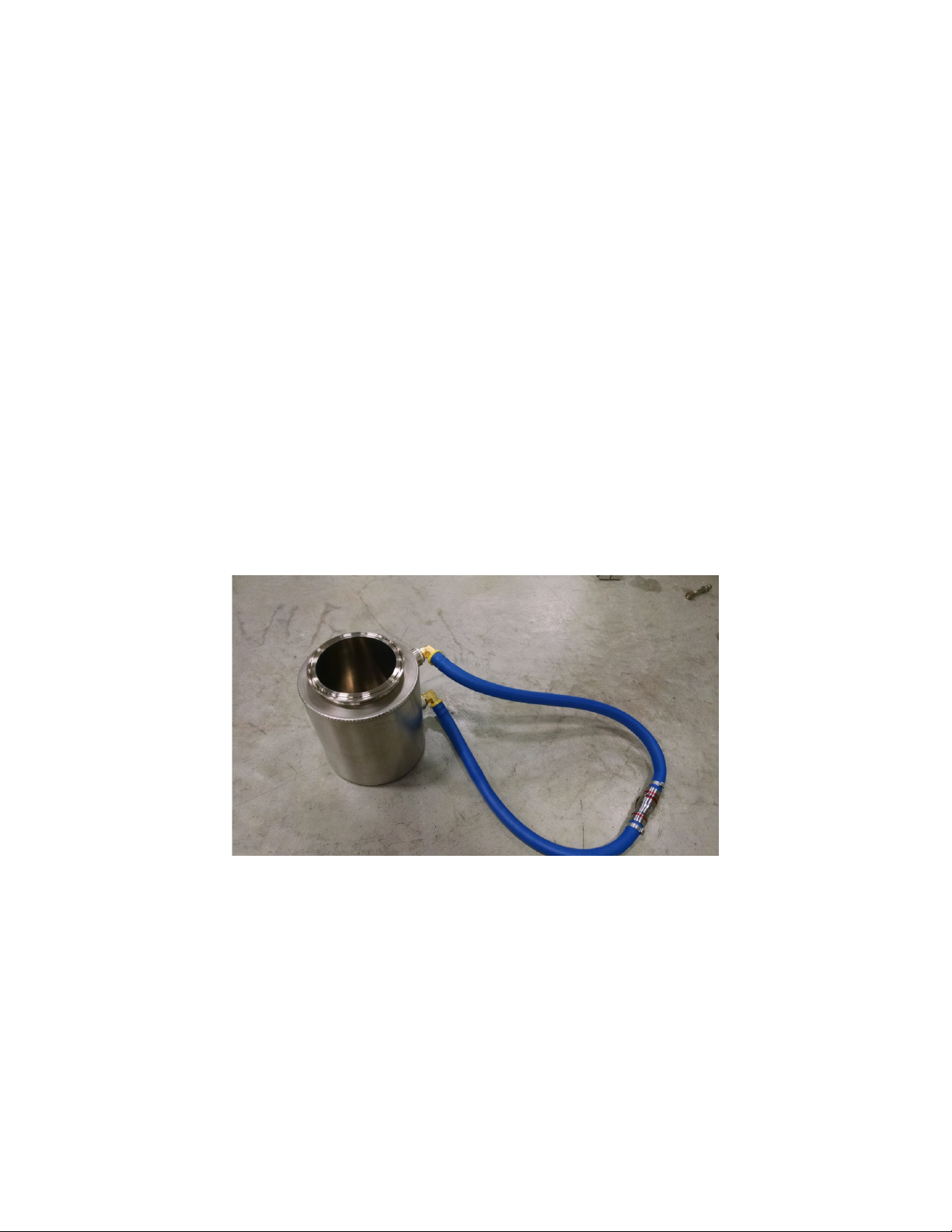
2.6.11. Disconnect the two blue water line quick connects on the collection cup. See Figure 12.
2.6.12. Attach the collector cup quick connects together and attach the bottom separator 1 quick connect to
the heat exchanger quick connect. This will ensure water flow even if collector cup connections are not
re-attached in assembly.
2.6.12.1. Caution:if removing the cup in the middle of a run with the pump on this step must be followed or
the system may automatically shut down due to lack of water flow.
2.6.13. Use caution to support and not to drop the collector cup, remove the high pressure sanitary clamps
from the bottom of the separator 1 with 5/8″ ratchet wrench.
2.6.14. Remove the collection cup from Separator #1.
2.6.15. Collect the oil from inside the collection cup.
2.6.15.1. Note: Oil will be carbonated with CO2and some dry ice may be present. This carbonation or dry ice
will sublimate without any additional heat. It is sometimes more efficient to remove the dry ice/oil
mixture and place it in collection device (like a Pyrex dish).
Figure 12. Image of collection cup after removal from separator.
2.6.16. Use the round squeegee and alcohol to thoroughly clean the inside of the separator and collection
cup.
2.6.17. Separator #1 and the collection cup must be cleaned after each extraction.
2.6.18. Reassemble separator #1 by reversing the steps above, excluding the connection piping from
Separator #1 to #2.
2.6.19. When reassembling, check gaskets for integrity and groove seals for cleanliness.
2.6.20. Prior to reassembling separator #1 cap, check orifice for clog and orientation.
2.6.21. Reconnect the collector cup water lines with quick connect to original configuration before turning on
the chiller/heater.
The Bambino® and The Transformer® Operation Manual
Updated 5/4/2021 12 © Apeks LLC, 2019
2.7. Closing Separation Vessels
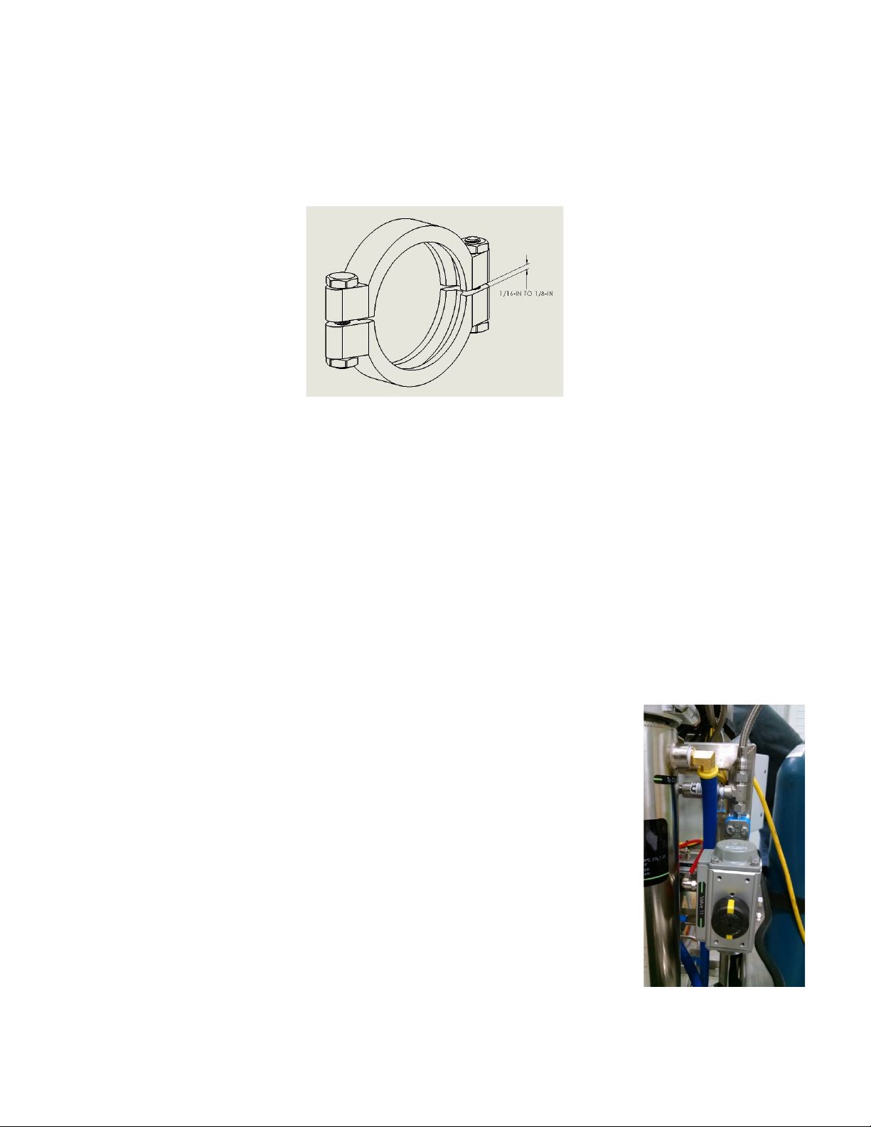
2.7.1. The separators are closed with sanitary clamps.
2.7.2. Clamps are considered tight when gaps between clamps are 1/16" to 1/8" between opposing sides of
the clamp as seen in Figure 13).
Figure 13. Appearance of tight sanitary clamp
2.8. Maintenance After Every Run
2.8.1. Includes harvesting oil and cleaning separator #1 as described in Section 2.6.
2.8.2. Separator #2:
2.8.2.1. Remove Separator #2 inlet and outlets line from separator cap.
2.8.2.2. Remove the top sanitary clamps and inspect Separator #2 for oil carryover.
2.8.2.3. Clean Separator #2 if any oil is present.
2.8.2.3.1. Remove bottom sanitary clamp.
2.8.2.3.2. Use the 3″squeegee and cleaning agent to thoroughly clean the inside of the separator.
2.8.2.3.3. Clean bottom cap and check gasket for integrity and groove cleanliness prior to reassembly.
2.8.2.4. If there is no oil carryover then check top cap gasket for integrity and groove for cleanliness prior
to reassembling clamps.
2.8.2.5. Clean connection piping between Separator #1 and #2 and reassemble.
2.8.2.6. Ensure separator caps are secured on top and bottom of separators,
and all flexible metal hoses are connected with the exception of the
Separator #2 outlet line.
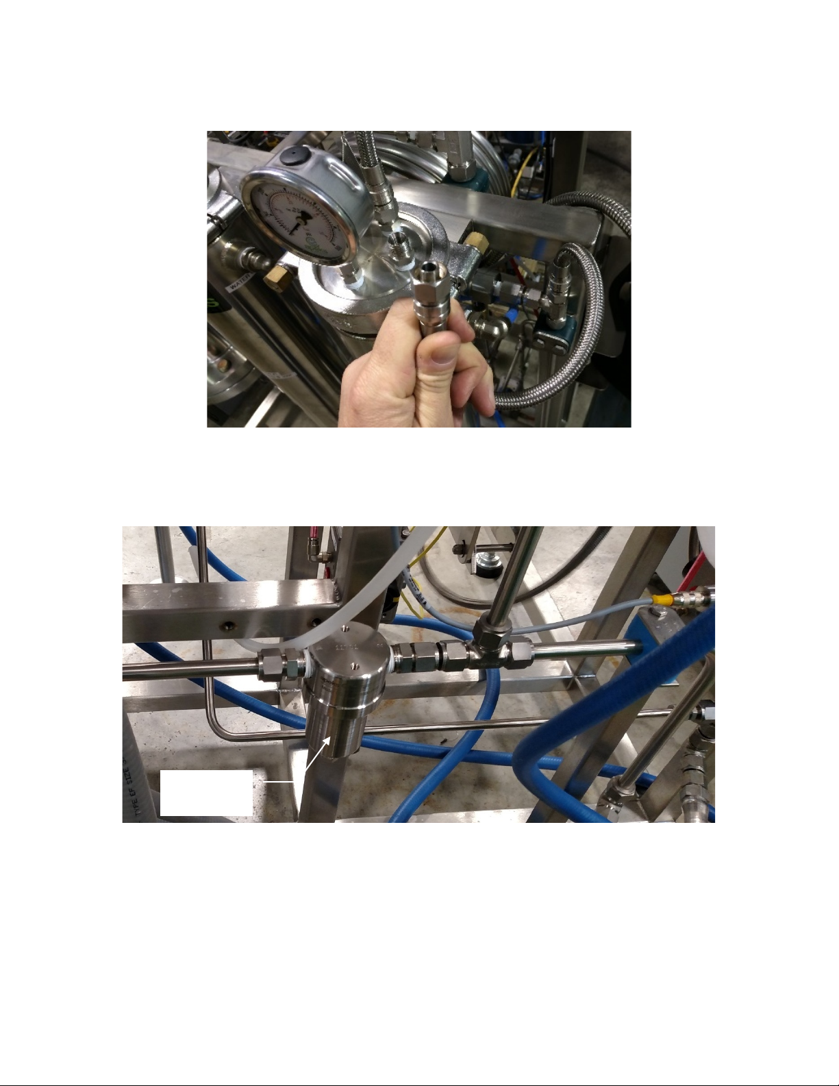
2.8.3. Separator #2 Outlet to Pump Inlet:
2.8.3.1. Ensure Valve 11 is open.
2.8.3.1.1. If Valve 11 isn’t open, then go to the manual screen and hit
“Evacuate”. This will open Valve 11. See Figure 14.
2.8.3.1.2. If the evacuation button is not present this means there is
entrained pressure somewhere in the system still and you may
need to reassemble the vessels and finish the recovery. Check
for pressure on the I/O Screen.
Figure 14. Valve 11 open
The Bambino® and The Transformer® Operation Manual
Updated 5/4/2021 13 © Apeks LLC, 2019
2.8.3.2. Disconnect the separator outlet line, if not already disconnected, from the cap of Separator #2 as
shown in Figure 15.
Figure 15. Image of separator outlet line after being disconnected
2.8.3.3. Remove the filter housing and filter on the back of the system. Inspect filter and housing for oil.
Clean housing and clean/replace filter as necessary. See Figures 16 and 17.
Figure 16. Filter Housing
Disconnect
Here

The Bambino® and The Transformer® Operation Manual
Updated 5/4/2021 14 © Apeks LLC, 2019
Figure 17. Filter Housing with bottom and filter removed
2.8.3.4. Pour cleaning agent into the separator outlet line using the supplied squeeze bottle (see Figure 20,
page 20) until the solvent is colorless coming out the end that was connected to the pump inlet.
After no color appears in solvent, use compressed air to blow out the line to ensure that NO
residual alcohol remains in the line between the separator and the pump.
2.8.3.5. Reconnect the separator outlet lines and reassemble filter.
2.8.3.6. The separator outlet line must be cleaned after every extraction.
The Bambino® and The Transformer® Operation Manual
Updated 5/4/2021 15 © Apeks LLC, 2019
2.9. Opening Extraction Vessel
WARNING
DO NOT ATTEMPT TO OPEN A VESSEL UNDER PRESSURE!
Always make sure a vent path for the vessel is opened and the
corresponding pressure gauge(s) reads zero prior to loosening the vessel closure bolts.
2.9.1. This operation cannot be performed during an extraction. The extraction must be stopped prior to
opening the extraction vessel.
2.9.2. Venting of the extraction vessel happens automatically at the end of recovery.
2.9.3. If the system is stopped and still has pressure you can go the “Manual Screen”. See Figure 5, page 6.
2.9.3.1. You can choose to hit “Recover CO2”, which will recover the CO2back into the bottle, or:
2.9.3.2. “Open Extractor Vessel” button, which will vent all CO2in the system, out of Valve 4.
2.9.3.3. If the extractor is under pressure, the system will require the operator to acknowledge that they
want to vent all the CO2in the extractor.
2.9.4. When the extractor vessel gauge on top of the vessel and on the home screen both read zero, it is safe
to move to the next step.
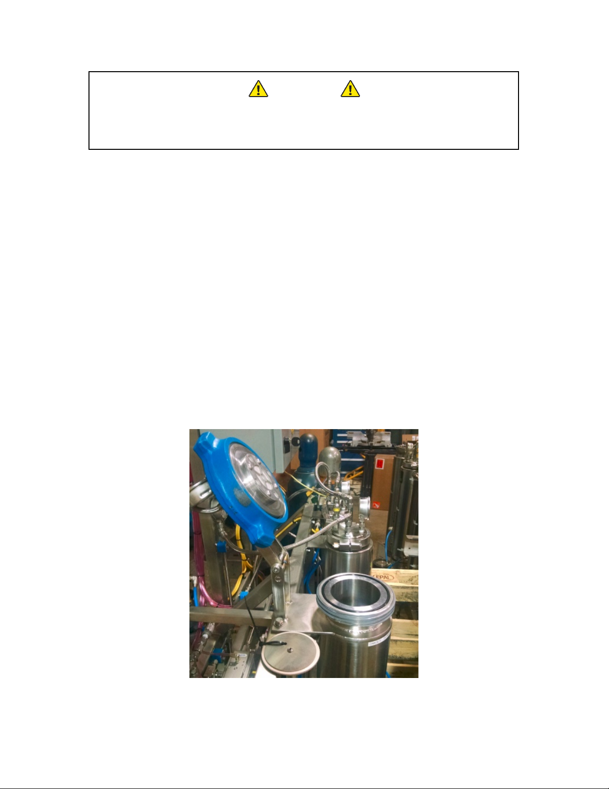
2.9.5. Use the supplied rubber mallet to loosen the extractor hammer unions from the top or bottom flange.
2.9.5.1. Caution: Extractor flange can weigh up to 50 lbs and care should be given to avoid damage and
injury.
2.9.6. Pivot the top flange toward the back and let it rest on the integral hinge stops (see Figure 18). The
bottom hammer union may not have a hinge, and must be lowered gently to prevent injury or damage
to the remote probe and/or hammer union.
2.9.6.1. Use caution not to scratch or otherwise damage the sealing surfaces on the flanges.
Figure 18. Appearance of extractor vessel in open condition
The Bambino® and The Transformer® Operation Manual
Updated 5/4/2021 16 © Apeks LLC, 2019
2.10. Removing Spent Material from Extraction Vessel
2.10.1. Once the extraction vessel is open, the spent botanical material can be removed. It is recommended all
material be removed from the top of the extractor using a large shop vac.
2.10.2. Alternatively, the bottom vessel closure can be opened using the same instructions provided in Section
2.9. With the bottom closure open the botanical material will fall out of the vessel and can be collected
in a bag or other collection device.
2.10.2.1. Warning: you will have to remove the temperature probe before opening the bottom vessel
closure. Failure to do so may result in bending and/or damaging the temperature probe.
2.10.2.2. Caution: removing material from the bottom can cause material to get into threads on the closure
nut. Threads will need to be cleaned and lubricated with anti-seize before reassembly.
2.10.2.3. Caution: Extractor flange can weigh up to 50 lbs and care should be given to avoid damage and
injury.
2.11. Loading Botanical Material
2.11.1. Prior to loading material visually check temperature probe and filter at the bottom as best you can
from the top of extractor vessel.
2.11.1.1. Caution: Extractor flange can weigh up to 50 lbs and care should be given to avoid damage and
injury.
2.11.2. Material to be extracted is loaded directly into the extraction vessel. The 4 qt funnel supplied in the
accessories box can be used to help minimize spillage.
2.11.2.1. Typically, botanicals perform best in CO2extractions when ground to a particle size between 200
µin (roughly the consistency of coffee grounds).
2.11.2.2. Any amount of material can be loaded into the extraction vessel – the vessel does not have to be
full in order to operate correctly.
2.11.3. Gentle compression or packing can be used to increase the amount of material loaded in the vessel,
however heavy compaction should be avoided because it can cause channeling of CO2during the
extraction process.
2.12. Closing Extraction Vessel
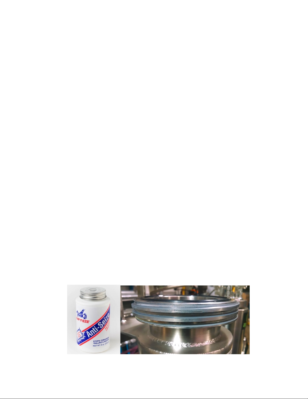
2.12.1. Ensure all sealing surfaces are clean and free of debris.
2.12.2. Check the cup seal or O-ring for any visible damage or defects. Replace if necessary.
2.12.3. Ensure the threads of the extractor are free of debris and greased with the supplied bottle of anti-seize
as shown in Figure 19.
Figure 19. Supplied bottle of Anti-Seize and threads

The Bambino® and The Transformer® Operation Manual
Updated 5/4/2021 17 © Apeks LLC, 2019
2.12.4. Thread on the hammer union. Use supplied rubber mallet to fully close vessel - three to five hits past
hand tight. The nut should close to approximately the same location each time. If it does not then
there may be debris in the threads that needs cleaned out.
2.12.4.1. If threads need cleaning remove all anti-seize lubricant from threads on both the vessel and the
nut.
2.12.4.2. Once all old material is removed reapply thin new layer.
2.13. Chiller Start Up
2.13.1. Every 80 hours verify chiller coolant level in chiller reservoir. If necessary, top off appropriate mix of
distilled water and propylene glycol. Glycol percentage can be determined using a refractometer with
is available on the online store.
2.13.2. Every 40 hours clean air filter on front of chiller.
2.13.3. Verify chiller cooling lines are connected to the extraction system.
2.13.4. Basic chiller commands:
2.13.4.1. Turn on chiller: press the power button on the front of the chiller. If that does not work, check to
make sure the chiller is connected to power and the breaker on the back of the chiller is on.
2.13.4.2. Set the target pressure: from the main screen, when setpoint is highlighted press enter to take you
to the current setpoint. To adjust setpoint press enter again till setpoint is flashing. Use arrows to
turn the setpoint up or down and then save by pressing enter.
2.13.4.3. Other options: other options such as changing units and monitoring values are located under the
menu section. Refer to chiller manual for more detail.
2.13.5. Check I/O Screen to verify there is water flow. If no water flow is detected check connections.
2.14. Evacuating System (Pulling Vacuum)
2.14.1. After loading material, and ensuring all vessels are closed and ready for normal operation, from the
Home Screen (see Figure 4, page 6), click the Manual Screen Button.
2.14.2. From the Manual Screen (see Figure 5, page 6), click the Evacuate Button.
2.14.2.1. Evacuation button will not appear if there is any pressure in the system. Refer to the I/O Screen
(see Figure 8, page 8) to find where there is pressure and relieve.
2.14.3. Verify that all the gauges on the system display zero pressure.
2.14.4. Verify that the supplied vacuum pump is filled with the appropriate oil.
2.14.4.1. Refer to the vacuum pump owner’s manual for more detailed information.
2.14.5. Connect the vacuum gauge, blue vacuum hose and vacuum pump to the evacuation valve on the
bottom of Separator #2.
2.14.6. Open the evacuation valve.
2.14.7. Turn on the vacuum pump.
2.14.8. Allow the pump to run for approximately five minutes or until the gauge is below 25 inHg (inches
mercury).
2.14.8.1. If the vacuum gauge does not reach -20 inHg, there may be a leak in the system or a vessel not
closed.
2.14.9. Close the evacuation valve.
2.14.10. Turn off the vacuum pump.
2.14.11. Disconnect the pump assembly (vacuum gauge, blue vacuum hose and pump).
2.14.12. Press the message button acknowledging that the evacuation is complete.
2.14.13. Return to the Home Screen.

The Bambino® and The Transformer® Operation Manual
Updated 5/4/2021 18 © Apeks LLC, 2019
2.14.14. CAUTION:Never depressurize separation vessels with the evacuation valve while vacuum pump or
gauge is attached.
2.15. Conducting an Extraction
2.15.1. If the green start button is not present at the bottom of the home screen, then do one of two things:
2.15.1.1. Push the orange button on the bottom of the home screen that says maintenance is required, and
this will then turn into a green start button.
2.15.1.2. Push the green button on the top right corner of the screen that says “Return to Auto Mode”, and
then a green start button will appear on the bottom of the home screen.
2.15.2. Verify that a 50 lb, 75 lb or 100 lb cylinder of CO2with a sufficient amount of CO2is connected to the
system. Refer to the Pre-Training Checklist (see Appendix F, page 35) for suggested bottle quantities.
Any time the bottle has less than 400psi, the pressure is considered low.
2.15.3. Verify that material is loaded into extraction vessel and extraction vessel is properly closed.
2.15.3.1. The system can be run with no material in the extraction vessel. This can be used as a way to clean
the stainless-steel tubing upstream of the separation vessel.
2.15.4. Verify that the separator vessels are both closed and sanitary clamps are tight (torqued to 20 ft-lbs).
2.15.5. Press the Start button on the home screen.
2.15.6. After pressing start, the system will prompt the operator to follow the following steps:
Caution: Failure to follow prompts could result in serious injury.
2.15.6.1. Set extractor pressure (between 900psi and 1900psi).
2.15.6.2. Set the System Run Time (between 1 hour and 48 hours).
2.15.6.2.1. The recommended run time is dependent on the material being extracted and the
extraction parameters but is typically between 1.5 to 3 hours per pound. Refer to the
Recommended Parameters in Section 2.16 on page 19.
2.15.6.3. Verify chiller is connected, turned on and set to the correct temperature.
2.15.6.4. Verify the extractor is properly closed.
2.15.6.5. Verify the separator is properly closed.
2.15.6.6. Close Valve 10 and evacuation valve (if evacuation was not conducted these may be open, if it was
then they should already be closed).
2.15.6.7. Open the CO2 bottles.
2.15.6.8. If you have a single extraction vessel the system will start filling the vessels with CO2to the target
extractor pressure.
2.15.6.8.1. If you have two extraction vessels the screen will prompt you to choose which extraction
vessel you will be using, either “A” (Extractor A only), “B” (Extractor B only) or “C” (both
extractor A and B at the same time).
2.15.6.8.2. After choosing which extraction vessel(s) you will be using, the screen will prompt you to
close and/or open valves 3A and 7A or 3B and 7B depending on which extraction vessel(s)
you choose to run.
2.15.6.8.3. The system will start filling the vessels with CO2to the target extractor(s) pressure.
2.15.6.9. During the filling stage the Home Screen will display a blue box labeled “Startup” to inform the
operator of the systems current activities.
2.15.7. Once the target extractor pressure is reached, the system information box will change from “Startup”
to “Running”. An additional information box will appear indicating the direction of the flow, either
“Forward Flow” or “Reverse Flow”.
2.15.7.1. Forward flow refers to CO2entering the top of the vessel and exiting the bottom. Reverse flow
enters the bottom and leaves the top.

The Bambino® and The Transformer® Operation Manual
Updated 5/4/2021 19 © Apeks LLC, 2019
2.15.7.2. The system switches the flow direction every run to flow clean CO2through the filter elements on
the extraction vessel.
2.15.7.3. The system will continue in run mode until it reaches the target run time, then it will start
recovering the CO2. The information box will switch from “Running” to “Recovering”.
2.15.8. At the end of recovery, the system will automatically vent the extraction vessel but the separation
vessels will have approximately 100 psi in them. The system will provide message boxes to instruct the
operator through the final shut down process. The prompts are:
2.15.8.1. Close the CO2cylinders and open Valve 10.
2.15.9. Once the operator acknowledges that the CO2cylinder are closed and Valve 10 is open, the system will
open all valves, vent any trapped CO2and wait for the next command.
2.16. Recommended Operating Parameters
2.16.1. Recommended default parameters are intended as a starting point and it is up to the operator to
determine best results for their operation. Please note that ambient temperature affects parameters
and the system will take at least an hour to equalize out.
2.16.2. Subcritical runs result in lighter color oils and less waxes while supercritical runs decrease time and can
increase yield.
2.16.3. PDC 3 Diaphragm Compressor – The Bambino®
Subcritical: Target Pressure: ..................................... 1,200psi
Chiller Setting: ........................................ 70-75oF
Propylene Glycol Percentage: ................ 10%
Orifice Size: ............................................ 22
Resultant Separator Pressure: ............... 350-400psi
Resultant Separator Temperatures: ...... 20-30oF
Extraction Time: ..................................... 2-3 hours per pound
Supercritical: Target Pressure: ..................................... 1,800psi
Chiller setting: ........................................ 105-110oF
Propylene Glycol Percentage: ................ 10%
Orifice Size: ............................................ 18
Resultant Separator Pressure: ............... 350-400psi
Resultant Separator Temperatures: ...... 30-40oF
Extraction Time: ..................................... 1-2 hours per pound
2.16.4. PDC 4 Diaphragm Compressor – The Transformer®
Subcritical: Target Pressure:...................................... 1,200psi
Chiller Setting:......................................... 70-75oF
Propylene Glycol Percentage:................. 10%
Orifice Size: ............................................37
Resultant Separator Pressure: ..............350-400psi
Resultant Separator Temperatures: ......20-30oF
Extraction Time: ..................................... 2-3 hours per pound
Supercritical: Target Pressure:...................................... 1,800psi
Chiller setting:......................................... 105-110oF
Propylene Glycol Percentage: ................ 10%
Orifice Size: ............................................. 29
The Bambino® and The Transformer® Operation Manual
Updated 5/4/2021 20 © Apeks LLC, 2019
Resultant Separator Pressure: ................ 350-400psi
Resultant Separator Temperatures: ....... 30-40oF
Extraction Time:...................................... 1-2 hours per pound
3. System Maintenance
This maintenance schedule is based on the maintenance timer on the Maintenance Screen (see Figure 6 on page 7).
3.1. Extraction System Maintenance
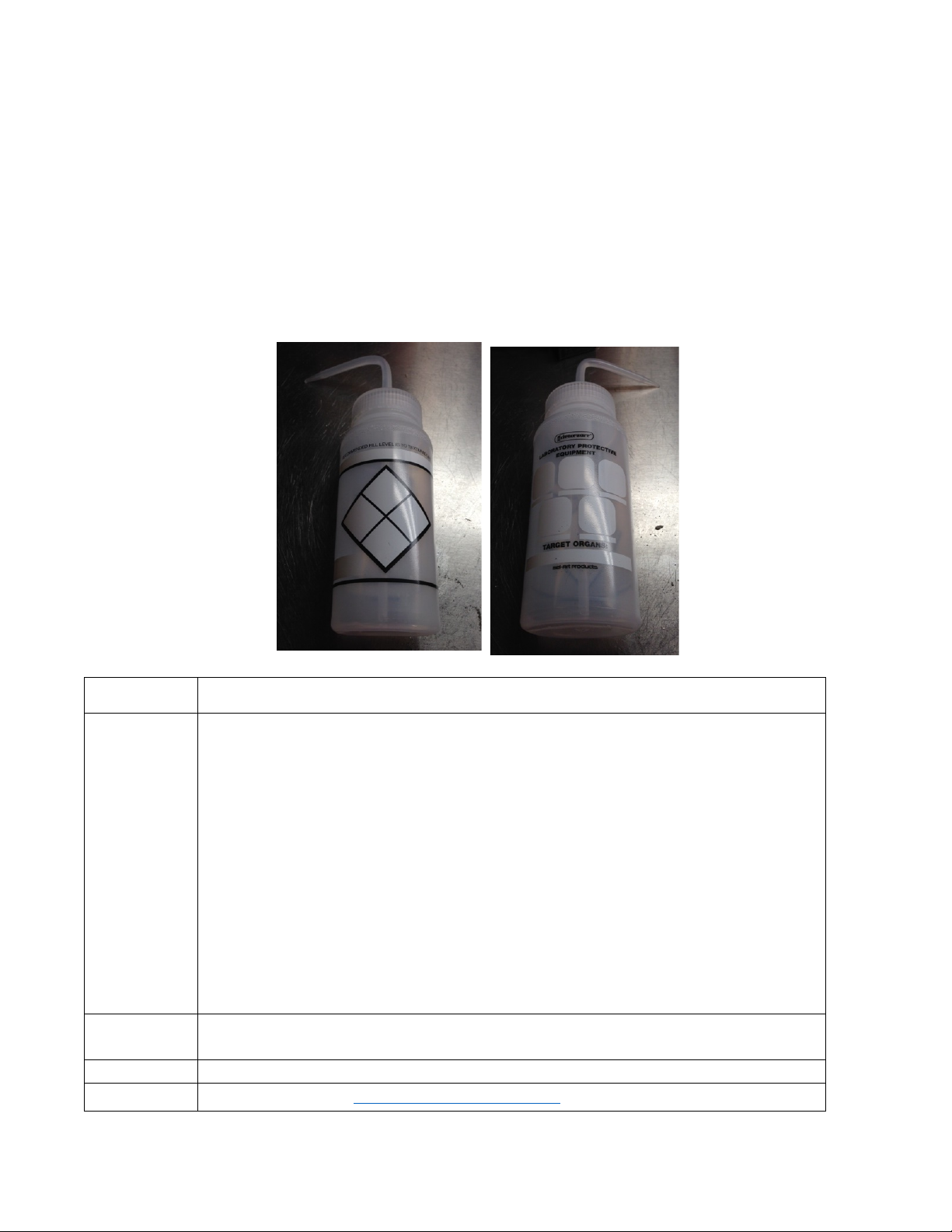
Included with each system is a small squeeze bottle (see Figure 20) to help with proper maintenance and cleaning of
your systems CO2 lines. Alcohol (200 proof) is a typical and acceptable cleaning agent. Please label the bottle accordingly.
Figure 20. Front and back of chemical squeeze bottle
Frequency
Maintenance Item
After Each
Extraction
•Remove extracted oil from collector cup and separator walls, clean walls and cup with
alcohol.
•Check separator 2 for oil carryover and clean if necessary.
•Inspect separator gaskets and grooves prior to reassembly.
•Clean piping between separator 1 and 2 with alcohol.
•Clean Separator 2 CO2outlet to pump inlet, ensure valve 11 is open.
•Remove spent material from the extraction vessel by vacuuming it out through the
top flange.
•Verify the extractor filters are clear and free of debris.
•Check extraction vessel O-rings and O-rings groove sealing surfaces for damage –
replace if necessary.
•Inspect the surfaces on extraction vessel to make sure they are free from dust and
debris. Failure to clean surfaces properly can cause vessel not to seal properly or
damage to the cup seal.
Every 80
Hours
•Run the system “empty of plant material” for 1 hour to clean the high pressure side
of the system and extraction vessel(s).
Yearly
•Check torque on all screws in electrical panels (see Appendix G).
Resource
•Apeks online store http://apeksonlinestore.com/
This manual suits for next models
1
Table of contents
Other Apeks Industrial Equipment manuals


Popular Industrial Equipment manuals by other brands


Textron
Textron GREENLEE SG4 instruction manual

Agilent Technologies
Agilent Technologies G1531-67000 instructions

Dover
Dover Triton 96 Series user guide

Metcalfe
Metcalfe GU4 Installation & operating instructions

Schmalz
Schmalz SNGi-AE operating instructions

Simplex
Simplex VSH SUPER Technical information installation instructions