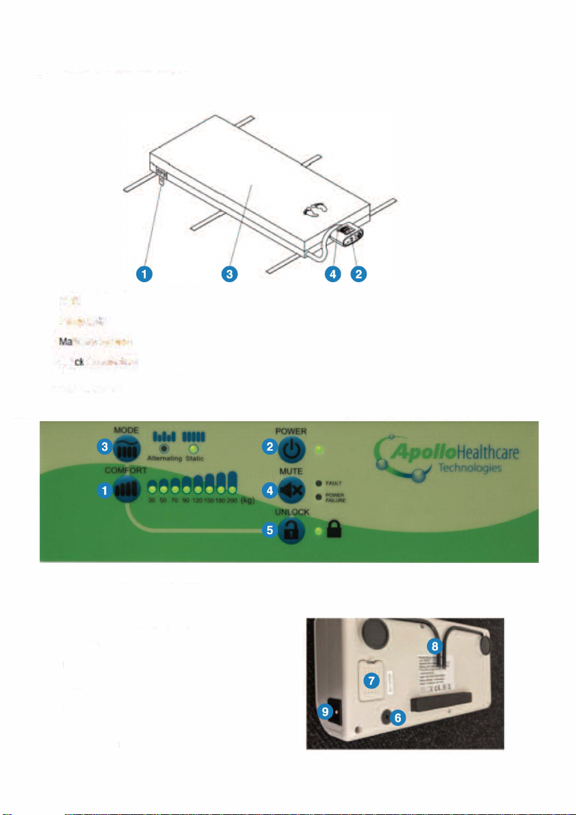
Apollo Healthcare Technologies Limited Apollo 5 Plus APHos2 User manual

Technologies
APHos2 Apollo 5 Plus™
APHos3 Apollo S™
USER MANUAL
AHSM-
001
_
Version
_5
_
08.4.2021
.apollo-ht.co.uk

BLE OF CONTENTS
5
8
SAVE INSTRUCTIONS

INSTRUCTIONS
DANGER - reduce the risk of electrocution:
RNING reduce the risk of burns, electrocution, fire or injury to Persons:
NOTE, CAUTION AND RNING SEMENTS:
CAUTION
RNING
2

SYMBOLS
Manufacturer
Complies with standards protecting against electric shock for type BF equipment.
Consult operating instructions for use
IP21 Protected against solid foreign objects of 12.5 mm and greater; Protection
against vertically falling water drops
Class II
Temperature limitation/temperature range
Dry clean, Any Solvent Except Trichloroethylene
Do Not Iron
Tumble Dry, Normal, Low Heat
Do Not Tumble Dry
Do Not Bleach
Do Not Dry Clean
Machine wash, regular / normal, max 95 degrees C (203 degrees F)
Attention – Observe proper Disposal of Electrical & Electronic Equipment (WEEE): This product
should be handed over to an appropriate collection point for the recycling of electrical and
electronic equipment. For more detailed information about the recycling of this product, please
contact your local city office, household waste disposal service or the retail store where you
purchased this product.
Caution
3

A. INTRODUCTION
/
/
/
/
3
/
3
3
S
R
G
B
H
k
U
3.
4.
5.
A.3 CONTRAINIDITIONS
k
u
j
4

B. PRODUCT DESCRIPTION
8.1 AIR PUMP AND MATERIALS
OR
Syem
O C
8.2 PUMP AND MERIALS
5

B. 3 FRONT PANEL
6

C. INSLLATION
C1 PUMP AND MTRESS INSLLATION
q
NOTE:
NOTE:
CAUTION:
6
7

D. OPERION
&
8

9

E. CLEANING
CAUTION, do NOT
°
°
DO NOT USE PHENOLS
F. STORAGE
NOTE:
G. MAINTENANCE
G.1 GENERAL
10

G.2 FUSE REPLACEMENT
T1A/
G.3 AIR FILTER REPLACEMENT
11

H. SPECIFICIONS
1
2
uw
b

10. TechnicalSpecification:
Item Specification
Power Supply (Note: Seerating label on the product) AC 220-240V 50 Hz, 0.09A (for 230V system)
Fuse Rating 500mA, 250V
Cycle time 12mins
Dimension (L x W x H) 27.5x13.5x9cm
Weight 1.3Kg
Environment
AtmosphericPressure 80KPa to 106KPa
Temperature
Operation: 5°C to 35°C (41°F to 95°F)
Storage: -15°C to 50°C (5°F to 122°F)
Shipping: -15°C to 70°C (5°F to 158°F)
Humidity
Operation: 10% to 90% non-condensing
Storage: 10% to 90% non-condensing
Shipping: 10 % to 90% non-condensing
Classification
Class II, Type BF, IP21
Applied Part: Air Mattress
Not suitable for use in the presence of a flammable
anesthetic mixture (No AP or APG protection)
Mattress Specification
Model T01 T05 T04(Cell-on-cell mattress)
Dimension (L x W x H) 200x90x10cm 200x90x10cm 200x90x20cm
Weight 5.31Kg 4.58Kg 9Kg
Max. Support Weight 180Kg 180Kg 200Kg
NOTE-
1. Consult the distributor or EU representative for further technical documents.
2. The specification is also suitable for other areas operating with same power supply.
3. Mattress dimension and weight is measured without foam cushion.
4. The manufacturer reserves the right to modify the specification without notice.
13

Appendix A: EMC Information
Guidanceandmanufacturer’sdeclaration‐electromagneticemissions
Thedeviceisintendedforuseintheelectromagneticenvironmentspecifiedbelow.Thecustomerortheuserofthedevice
shouldassurethattheyareusedinsuchanenvironment.
EmissionstestComplianceElectromagneticenvironment‐ guidance
RFemissions
CISPR11
Group1ThemodelsdeviceuseRFenergyonlyfortheirinternalfunction.Therefore,theirRF
emissionsareverylowandarenotlikelytocauseanyinterferenceinnearbyelectronic
equipment.
RFemissions
CISPR11
ClassBThemodelP08Earesuitableforusedindomesticstablishmentandinestablishment
directlyconnectedtoalowvoltagepowersupplynetworkwhichsuppliesbuildingsusedfor
domesticpurposes.
Harmonic
emissions
lEC61000‐3‐2
ClassA
Voltage
fluctuations
/flicker
emissions
lEC61000‐3‐3
Complies
Warning:
1. Thedeviceshouldnotbeusedadjacenttoorstackedwithotherequipment.Ifadjacentorstackeduseisnecessary,the
deviceshouldbeobservedtoverifynormaloperationintheconfigurationinwhichitwillbeused.
2. Useofaccessories,transducersandcablesotherthanthosespecifiedorprovidedbythemanufacturerofthisequipment
couldresultinincreasedelectromagneticemissionsordecreasedelectromagneticimmunityofthisequipmentandresultin
improperoperation.
3. PortableRFcommunicationsequipment(includingperipheralssuchasantennacablesandexternalantennas)shouldbe
usednocloserthan30cm(12inches)toanypartofthePump,includingcablesspecifiedbythemanufacturer.Otherwise,
degradationoftheperformanceofthisequipmentcould result.
14

GuidanceandDeclaration‐electromagneticimmunity
Themodelsdeviceintendedforuseintheelectromagneticenvironmentspecifiedbelow.Thecustomerortheuserofthedeviceshould
assurethattheyareusedinsuchanenvironment.
ImmunitytestIEC60601
testlevel
Compliance
level
Electromagneticenvironment‐guidance
Electrostatic
discharge
(ESD)lEC
61000‐4‐2
±8kVcontact
±2kV,±4kV,±8kV,
±15kVair
±8kVcontact
±2kV,±4kV,±8kV,±15kV
air
Floorsshouldbewood,concreteorceramictile.If
floorsarecoveredwithsyntheticmaterial,the
relativehumidityshouldbeatleast30%.
Electricalfast
transient/burs
t
IEC61000‐4‐4
±2kVforpowersupplylines
±1kVforInput/outputlines
±2kVforpowersupplylines Mainspowerqualityshouldbethatofatypical
commercialorhospitalenvironment.
Voltagedips,
short
interruptions
and
voltage
variationson
powersupply
input
lines
IEC
61000‐4‐11.
<5%UT
(>95%dipinUT.)
for0.5cycle
<5%UT
(>95%dipinUT)
for1cycle
70%UT
(30%dipinUT)
for25/30cycles
<5%UT
(>95%dipinUT)
for5/6sec
<5%UT
(>95%dipinUT.)
for0.5cycle
<5%UT
(>95%dipinUT)
for1cycle
70%UT
(30%dipinUT)
for25/30cycles
<5%UT
(>95%dipinUT)
for5/6sec
Mainspowerqualityshouldbethatofatypical
commercialorhospitalenvironment.Iftheuserof
themodelP08requirecontinuedoperationduring
powermainsinterruptions,itisrecommendedthatthe
modelP08poweredfromanuninterruptible
powersupplyorabattery.
Power
frequency
(50/60Hz)
magneticfield
lEC61000‐4‐8
30A/m30A/m Powerfrequencymagneticfieldsshouldbeatlevels
characteristicofatypicallocationina
typicalcommercialorhospitalenvironment.
NOTEUTisthea.c.mainsvoltagepriortoapplicationofthetestlevel.
Conducted
RFlEC
61000‐4‐6
3Vrms
150kHzto80MHz
6VrmsinISMandamateur
radiobands
3Vrms
150kHzto80MHz
6VrmsinISMandamateur
radiobands
PortableandmobileRFcommunicationsequipment
shouldbeusednoclosertoanypartofthemodels
P08includingcables,thantherecommended
separationdistancecalculatedfromtheequation
applicabletothefrequencyofthetransmitter.
Recommendedseparationdistance
d=[3,5/V1]xP1/2
Radiated
RFlEC
61000‐4‐3
10V/m
80MHzto2.7GHz.
10V/m
80MHzto2.7GHz
d=1,2xP1/280MHzto800MHz
d=2,3xP1/2800MHzto2.7GHz
385MHz‐5785MHz
TestspecificationsforENCLOSUREP
ORTIMMUNITYtoRF
wirelesscommunicationequipmen
t(Refertotable9ofIEC
60601‐1‐2:2014)
385MHz‐5785MHz
Testspecificationsfor
ENCLOSUREPORTIMMUNIT
YtoRF
wirelesscommunicationeq
uipment(Refertotable9of
IEC60601‐1‐2:2014)
wherePisthemaximumoutputpowerratingof
thetransmitterInwatts(W)accordingtothe
transmittermanufactureranddIsthe
recommendedseparationdistanceinmeters(m).
FieldstrengthsfromfixedRFtransmitters,
asdeterminedbyanelectromagneticsite
survey,ashouldbelessthanthecompliancelevelin
eachfrequencyrange.bInterferencemayoccurInthe
vicinityofequipmentmarkedwiththefollowing
symbol:
NOTE1At80MHzand800MHz.thehigherfrequencyrangeapplies.
NOTE2Theseguidelinesmaynotapplyinallsituations.Electromagneticpropagationisaffectedby
absorptionandreflectionfromstructures,objectsandpeople.
a) Fieldstrengthsfromfixedtransmitters,suchasbasestationsforradio(cellular/cordless)telephonesandlandmobileradios,amateurradio,
AMandFMradiobroadcastandTVbroadcastcannotbepredictedtheoreticallywithaccuracy.Toassesstheelectromagneticenvironment
duetofixedRFtransmitters,anelectromagneticsitesurveyshouldbeconsidered.Ifthemeasuredfieldstrengthinthelocationinwhichthe
modelsP06AisusedexceedstheapplicableRFcompliancelevelabove,themodelP06Ashouldbeobservedtoverifynormaloperation.If
abnormalperformanceisobserved,additionalmeasuresmaybenecessary,suchasreorientingorrelocatingthemodelP06A.
b) Overthefrequencyrange150kHzto80MHz,fieldstrengthsshouldbelessthan3V/m.
15

RecommendedseparationdistancesbetweenportableandmobileRFcommunicationsequipmentandthemodelP08E
ThemodelP08EisintendedforuseinelectromagneticenvironmentinwhichradiatedRFdisturbancesiscontrolled.The
customerortheuserofthemodelP08Ecanhelppreventelectromagneticinterferencebymaintainingaminimumdistance
betweenportableandmobileRFcommunicationsequipment(transmitters)andthemodelP08Eisrecommendedbelow,
accordingtothemaximumoutputpowerofthecommunicationsequipment.
Ratedmaximum
outputPowerof
transmitter
W
Separationdistanceaccordingtofrequencyoftransmitter
m
150kHzto
80MHz
d=1.2xP1/2
80MHzto
800MHz
d=1.2xP1/2
800MHzto2,5GHz
d=2.3xP1/2
0.010.120.120.23
0.10.380.380.73
11.21.22.3
103.83.87.3
100121223
Fortransmittersratedatamaximumoutputpowernotlistedabove,therecommendedseparationdistancedinmeters(m)
canbeestimatedusingtheequationapplicabletothefrequencyofthetransmitter,wherePisthemaximumoutputpower
ratingofthetransmitterinwatts(W)accordabletothetransmittermanufacturer.NOTE1At80MHzand800MHz.the
separationdistanceforthehigherfrequencyrangeapplies.
NOTE2Theseguidelinesmaynotapplyinallsituations.Electromagneticpropagationisaffectedbyabsorptionand
reflectionfromstructures,objectsandpeople.
16

SE THESE INSTRUCTIONS
NOT
For further technical support please visit
1
7

chnologies
This manual suits for next models
1
Table of contents
Other Apollo Healthcare Technologies Limited Medical Equipment manuals
Popular Medical Equipment manuals by other brands

Mobiak
Mobiak ASPER user manual

Stryker Medical
Stryker Medical 1075 Operation and maintenance manual

INTERSON
INTERSON Simpli Series Instructions for use

SCIEX
SCIEX P/ACE MDQ Plus System Maintenance Guide

TR Equipment
TR Equipment TR 4000 Atlas operating manual

Ludlum Measurements
Ludlum Measurements 4906 Technical manual