EG4 3000 EHV-48 User manual

April 2022 | Rev A | Information subject to change without notice.

Table Of Contents
ABOUTTHISMANUAL....................................................................................................................................................1
Purpose.............................................................................................................................................................................1
Scope.................................................................................................................................................................................1
SAFETYINSTRUCTIONS...............................................................................................................................................1
INTRODUCTION...............................................................................................................................................................6
ProductOverview............................................................................................................................................................7
INSTALLATION.................................................................................................................................................................8
UnpackingandInspection..............................................................................................................................................8
Preparation.......................................................................................................................................................................8
MountingtheUnit............................................................................................................................................................8
BatteryConnection..........................................................................................................................................................9
ACInput/OutputConnection.......................................................................................................................................10
PVConnection................................................................................................................................................................12
FinalAssembly................................................................................................................................................................13
DryContactSignal........................................................................................................................................................14
OPERATION....................................................................................................................................................................15
PowerON/OFF...............................................................................................................................................................
15
OperationofDisplayPanel..........................................................................................................................................15
LCDDisplayIcons.........................................................................................................................................................16
ProgramSetting............................................................................................................................................................18
DisplaySetting............................................................................................................................................................... 26
OperatingModeDescription........................................................................................................................................ 30
/ITHIUMBATTERY6(77,1*6..........................................................................................................................50
SPECIFICATIONS........................................................................................................................................................... 2
TROUBLESHOOTING..................................................................................................................................................55
ParallelInstallationGuide........................................................................................................................................33
1. Instruction................................................................................................................................................................ 33
2. PackageContents.....................................................................................................................................................33
3. MountingtheUnit.....................................................................................................................................................33
4. WiringConnection....................................................................................................................................................34
5. ParallelOperationinSinglephase.........................................................................................................................36
6. Support3-phaseequipment...................................................................................................................................39
7. Supportsplitphase...................................................................................................................................................41
8. PVConnection...........................................................................................................................................................
42
9. 6SOLW3KDVHDQG3KDVHLCDSettingandDisplay..............................................................................................43
C
Commissioning......................................................................
...........
.................................................................................
45
7\SLFDO$SSOLFDWLRQ........................................................................................................................................................3

1
ABOUT THIS MANUAL
Purpose
Thismanualdescribestheassembly,installation,operationandtroubleshootingofthisunit.Pleaseread
thismanualcarefullybeforeinstallationandoperation.
Scope
This manual provides safety and installation guidelines as well as information on tools and wiring.
SAFETY INSTRUCTIONS
WARNING: This chapter contains important safety and operating instructions. Read and
keep this manual for future reference.
1ˊBefore using the unit, read all instructions and cautionary markings on the unit, the batteries and all
appropriatesectionsofthismanual.
2ˊCAUTION
To
reduce
risk
of
injury,
charge
only
deep-cycle
lead
acidRU
/L,RQW\SH rechargeable
batteries.
Other
types
of
batteries
may
burst,
causing
personal
injury
and
damage.
3ˊDonotdisassembletheunit.:KHQVHUYLFHRUUHSDLULVUHTXLUHGWakeittoaqualifiedservicecenter
Incorrectre-assemblymayresultinariskofelectricshockorfire.
4ˊToreduceriskofelectricshock,disconnectallwiringsbeforeattemptinganymaintenanceorcleaning.
Turningofftheunitwillnotreducethisrisk.
5ˊCAUTION–
Only
qualified
personnel
VKRXOG
install
this
device
withD
battery.
6ˊNEVERchargeafrozenbattery.
7ˊForoptimumoperationofthisinverter/charger,pleasefollowrequiredspectoselectappropriate
cablesize.
8ˊBeverycautiouswhenworkingwithmetaltoolsonoraroundbatteries.ApotentialriskexistsIRUD
dropSHGtooltosparkorshortcircuitbatteriesotherelectricalpartscausLQJanexplosion.
9ˊPleasestrictlyfollowinstallationprocedurewhendisconnectLQJACorDCterminals.Pleasereferto
INSTALLATIONsectionSJ8ofthismanualIRUdetails.
10ˊFuseisprovidedasover-currentprotectionforthebatterysupply.
11ˊGROUNDINGINSTRUCTIONS-Thisinverter/chargershouldbeconnectedtoapermanentgrounded
wiringsystem.BesuretocomplywithlocalrequirementsandregulationZKHQinstallLQJthisinverter.
12ˊNEVERVKRUWACoutputRUDCinputV.DoNOTconnecttotheJULGZLWKDVKRUWHGDCinput
13ˊWarning!!
Only
qualified
SHUVRQQHO
are
able
to
service
this
device.
If
errors
still
persist
after
following
troubleshooting
table,
please
send
this
inverter/charger
back
to
local
dealer
or
service
center
for
maintenance.
2
SPECIFICATIONS
Table 1 Line Mode Specifications
INVERTER MODEL (+9
Input Voltage Waveform 6LQXV RLGDOXWLOLW\ RUJH QHUD WRU
Nominal Input Voltage 9DF
Low Loss Voltage 9DF9836
9DF9$SSOLDQFHV
Low Loss Return Voltage 9DF9836
9DF9$SSOLDQFH V
High Loss Voltage 9DF9
High Loss Return Voltage 9DF9
0D[$&,QSXW9ROWDJH 9DF
Nominal Input Frequency +] +] $XWR GH WHFWLRQ
Low Loss Frequency +]
Low Loss Return Frequency +]
High Loss Frequency +]
High Loss Return Frequency +]
Output Short Circuit Protection /LQH PRGH &LUFXLW%UHDNHU 30$
%DWWHU\ PRGH 6ROLG6WDWH)(7V$
Efficiency (Line Mode) 5DWH G5ORD G EDWWH U\ IXOOFKDUJH G
Transfer Time PV W\SLFDO836PV W\SLFDO
$SSOLDQFHV
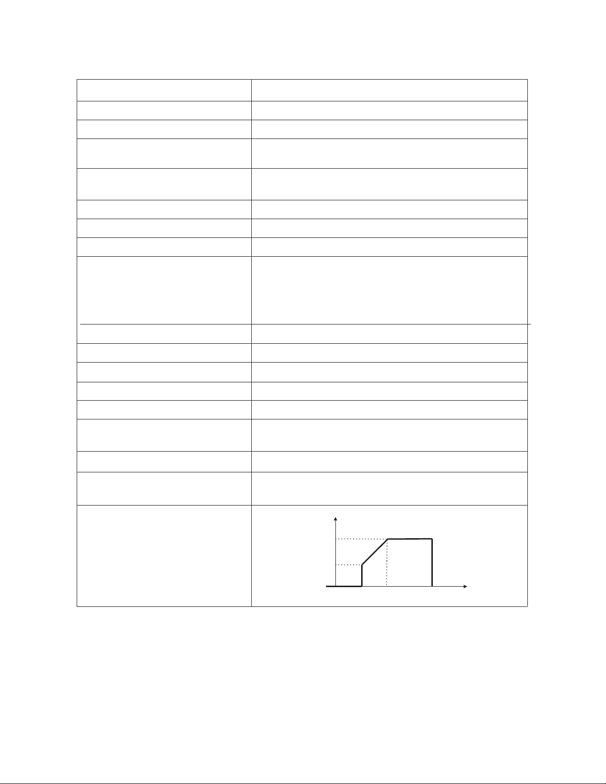
2XWSXWSRZHUGHUDWLQJ
:KHQ $& LQSXW YROWDJH GURSV WR 9
WKH RXWSXW SRZHUZLOOEH GHUDWHG
Output Power
Rated Power
50%
Power
65V 95V 140V Input Voltage
0LQ$&,QSXW9ROWDJH (OHFWURQLFV9$&
+RPH$SSOLDQFHV9$&

Table 2 Inverter Mode Specifications
INVERTER MODEL (+9
Rated Output Power 3KVA/3KW
2XWSXW9ROWDJH:DYHIRUP Pure Sine Wave
Output Voltage Regulation 110/120Vac±5%
Output Frequency 60Hz or 50Hz
%DWWHU\WR,QYHUWHUEfficiency 94%
Overload Protection 5s@150% load; 10s@110%~150% load
Surge Capacity 2* rated power for 5
seconds
Nominal DC Input Voltage 48Vdc
03376WDUWXSVoltage Vdc
/RZ'&:DUQLQJ9ROWDJH
@load<20%
@20%load<50%
@load50%
44.0Vdc
42.8Vdc
40.4Vdc
Low DC Warning Return Voltage
@ load < 20%
@20%load < 50%
@load50%
46.0Vdc
44.8Vdc
42.4Vdc
LowDCCut-offVoltage
@load<20%
@20%load<50%
#ORDG
42.0Vdc
40.8Vdc
38.4Vdc
39WR,QYHUWHU(IILFLHQF\
Table3ChargeModeSpecifications
8WLOLW\&KDUJLQJ0RGH
INVERTER MODEL (+9
Charging Current (AC) 60Amp
(@ VI/P=120Vac)
Charging Current
(PV+AC)
80Amp
(@ VI/P=120Vac)
Bulk
Charging
Voltage
Flooded
Battery 58.4 Vdc
AGM / Gel
Battery 56.4 Vdc
Floating Charging Voltage 54Vdc
Overcharge Protection 63Vdc
&KDUJLQJ$OJRULWKP 3-Step

4
Charging Curve
Battery Voltage, per cell Charging Current, %
2.43Vdc (2.35Vdc)
Voltage
2.25Vdc
100%
50%
T0 T1
T1 = 10* T0, minimum 10mins, maximum 8hrs
Current
Time
Bulk Absorption Maintenance
(Constant Current) (Constant Voltage) (Floating)
Solar Input
INVERTER MODEL 3(+9
Rated Power 5000W
Max. PV Array Open Circuit
Voltage 500Vdc
PV Array MPPT Voltage
Range 120Vdc~450Vdc
Max. Current'UDZ 18A
Max Charging Current(PV) 80A
Table 4 General Specifications
INVERTER MODEL (+9
Safety Certification CE
Operating Temperature
Range -10°C to 55°C
Storage temperature -15°C~ 60°C
Humidity 5% to 95% Relative Humidity (Non-condensing)
Dimension (D*W*H) 448PPx295PPx105PP(122PP)
1°C to °)
°C to °)
xx()
Net Weight, kgOE 9.9(10.2) OE()
1XPEHURI0337
6WDUW8S9ROWDJH
9'&
56 <(6
56 <HV86%7\SH$
'U\&RQWDFW <HV
,GOH3RZHU&RQVXPSWLRQ ::6DYLQJ0RGH
,35DWLQJ ,3,QGRRU8VH
:DUUDQW\
aP
<HDUV
86% 1R86%3RUW
2SHUDWLQJ$OWLWXGH

Table3DUDOOHO6SHFLILFDWLRQV
INVERTER MODEL (+9
0D[LPXP8QLWVLQ3DUDOOHO
&LUFXODWLRQ&XUUHQW
1R/RDG $
3RZHU,PEDODQFH5DWLR
3DUDOOHO&RPPXQLFDWLRQ &$1
7UDQVIHU7LPHLQ
3DUDOOHO0RGH PV
3DUDOOHO.LW %XLOW,Q5-3RUW
5

6
INTRODUCTION
This is a multi-function inverter/charger, combining WKHFDSDELOLWLHV ofDQ inverter, MPPT solar charger
and battery charger to offer XQLQWHUUXSWHG power support LQD portable size. Its comprehensive LCD
display offers user-configurable and easy-accessible button operation LQFOXGLQJ battery charging current,
AC/solar charger priority, and acceptable input voltage based on different applications.
)HDWXUHV
x
Pure sine wave inverter7+'
x
Built-in MPPT solar controller9WR9
x
Configurable input voltage range for home appliances and personal computers9WR9$&
x
Configurable battery charging current based on applications$WR$
x
Configurable AC/Solar Charger priority
x
Compatible to XWLOLW\JULG or generator poweU9
x
Auto restart whHQ$&LQSXWLVUHVWRUHG
x
Overload/ Over temperature/ 6hort circuit protection
x
6Part battery charger design for optimized battery performance
Basic System Architecture
The following illustration shows basic application for this inverter/chargerLncludLQJ WKHEHORZOLVWHG
devices QHHGHGIRU a complete running system:
x
Generator or Utility
x
9%DWWHU\
x
390RGXOHV
Consult with your system integrator for other possible system architectures depending on your requirements.
This inverter can power all kinds of appliances inD home or office environment, including FRPSUHVVRUEDVHG
appliances such as DUefrigerator RU air conditioner.
Figure 1 6RODU3ower System

7
Product Overview
LCD display
Status indicator
Charging indicator
Fault indicator
Function buttons
Power on/off switch
AC input/1
AC output/1
PV input9GF0D[
Battery input91RPLQDO
$&,QSXWCircuit breaker
RS232 communication portIRU
:L)LFRPPXQLFDWLRQ
Parallel communication port (only
for parallel model)
Dry contact (Optional)
USB communication portIRU3&
$SSOLFDWLRQV
RS485%06Fommunication port
GroundLQJ6FUHZ
8
INSTALLATION
Unpacking and Inspection
Before installation, please inspect the unitWREH sure that nothing inside the package is damaged. You
should have received the following items:
x:L)L&RPPXQLFDWLRQV0RGXOH
x5-WR'%PDOH56&DEOH
x5-SDWFKFDEOH
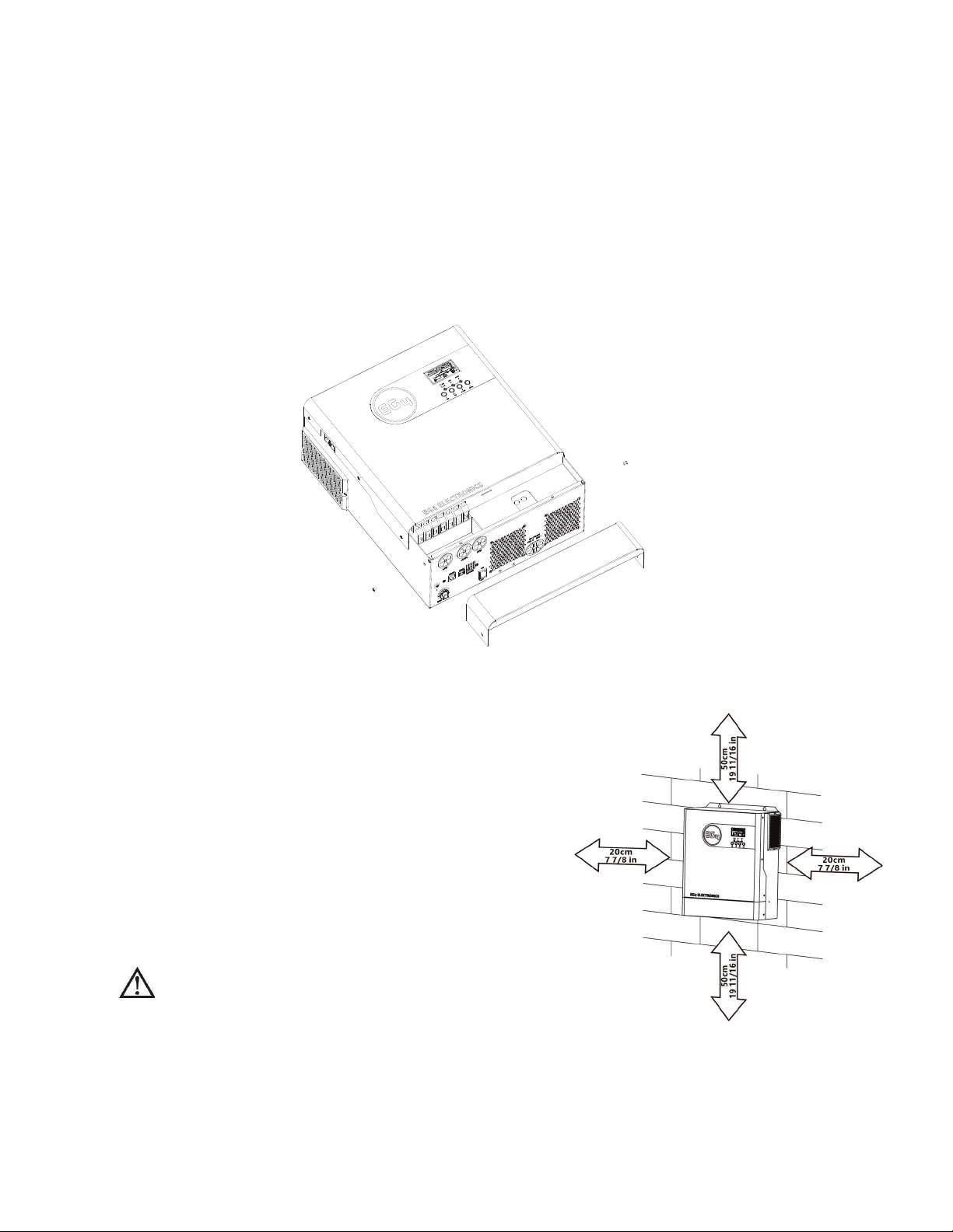
Preparation
Before connecting all wiring, pleaseUHPRYHWKHERttom cover by removing two screws as shown below.
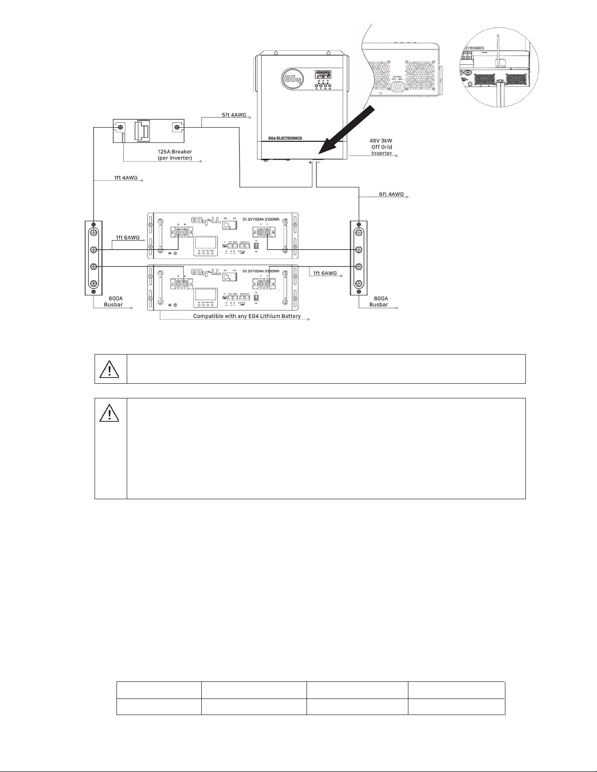
Mounting the Unit
Consider the following points before selecting where to install:
z
Do not mount the inverter on flammable
construction materials.
z
Mount on a solid surface
z
Install this inverter at eye level in order to allow
the LCD display to be read at all times.
z
The ambient temperature should be between 0°C
WR5°C )WR)Wo ensure optimal operation.
z
The recommended installation position is to be adhered
to the wall vertically.
z
Be sure to GLVWDQFH other objects and surfaces as
shown in the right diagram to guarantee sufficient heat
dissipation and to have enough space for removing wires.
SUITABLE F25,1'225MOUNTING ON
CONCRETE OR OTHER NON-COMBUSTIBLE
SURFACE ONLY.
x(*(+9,QYHUWHU
x8VHUPDQXDO
x%DWWHU\%06&DEOH
x$'&%UHDNHU
x',15DLO
x5HGDQG%ODFN$:*%DWWHU\&DEOH

9
Install the unit by screwing three screws. It’s recommended to use M4 or M5 screws.
Battery Connection
CAUTION:
For safety operation and regulation compliance, itLsrHFRPPHQGHG WKDW a separate DC over-current
protector or disconnect device LV LQVWDOOHG between battery and inverter.
Please refer to typical amperageOLVWHGEHORZ IRU required fuse or breaker size.
Stripping Length:
WARNING!
:HUHFRPPHQGDOOZLULQJEHSHUIRUPHGE\DOLFHQVHGSURIHVVLRQDO
WARNING!
It Ls very important for system safety and efficient operation to use WKH
appropriate cableVL]H for battery connection. To reduce risk of injury, please use the
recommended cable stripping length(L2)GTJ ZOTTOTM RKTMZN2狣 OTZNKZGHRK below.
Recommended battery cablestripping length (L2)and tinning length(L1):
Model Maximum
Amperage
Battery
capacity
Wire Size L1
(mmLQ)L2
(mmLQ)
Torque
value
(+9 A100AH 4AWG 3 18 2~ 3 Nm
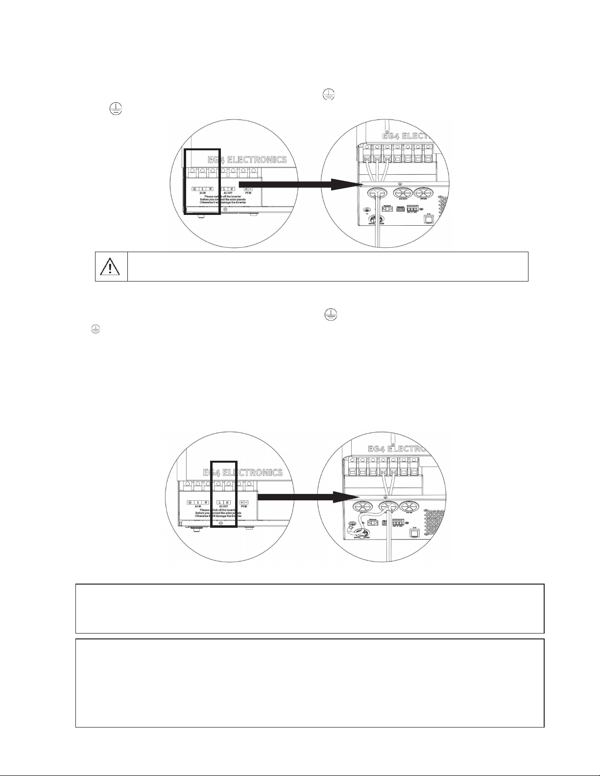
Please follow WKHIROORZLQJ steps to implement battery connection:
1.
Remove insulation sleeve 18 mm for positive and negative cables based on recommended stripping
length.
Connect all battery packs as unit requiresDQG use recommended battery capacity.
Insert battery cable WRWKH battery connector of inverter and make sure the bolts are tightened
with torque of 2-3 Nm. Make sure polarity at both the battery and the inverter/charge is
correctly connected and battery cables are tightly screwed to the batteryFRQQHFWRU
5HFRPPHQGHG
Wire Size
:LUH/HQJWK
PXSWRP
Wire Size
$:*PP
3OHDVH1RWH0D[LPXPFXUUHQWGUDZQE\WKHLQYHUWHULV$,IXVLQJ(*%DWWHULHVWKHPD[LPXP
RXWSXWLV$$$EUHDNHULVXWLOL]HGWRVXSSRUWPD[LPXPEDWWHU\FXUUHQWRI$,IXVLQJ
EDWWHULHVRWKHUWKDQ(*SOHDVHFRQVXOWWKHPDQXIDFWXUHUVPDQXDOWRHQVXUHSURSHUEUHDNHUVL]H
PP
10
WARNING: Shock Hazard
Installation must be performed with care due to high battery voltage in series.
CAUTION!! Do not place anything between the flat part of the inverter terminalOverheating
may occur.
CAUTION!! Do not apply anti-oxidant substance on the terminals before terminals are
connected tightly.
CAUTION!! Before making the final DC connection or closing DC breaker/disconnector, be sure
positive (+) LV connected to positive (+) and negative (-) LV connected to negative (-).
AC Input/Output Connection
CAUTION!!
Before
connecting
to
AC
input
power
source,
please
install
a
separate
AC
breaker
between
inverter
and
AC
input
power
source.
This
will
ensure
the
inverter
can
be
securely
disconnected
during
maintenance
and
fully
protected
from
$&
LQSXW
over
current.
5ecommended
specLILFDWLRQ
of
AC
breaker
is
30A
RQWKHLQSXWDQG$RQWKHRXWSXW
CAUTION!!
There
are
two
terminal
blocks
with
“IN”
and
“OUT”
markings.
Please
do
NOT
mis-connect
input
and
output
connectors.
WARNING!
:HUHFRPPHQGDOOZLULQJEHSHUIRUPHGE\DOLFHQVHGSURIHVVLRQDO
WARNING!
It
Ls
very
important
for
system
safety
and
efficient
operation
to
use
appropriateO\VL]HG
cable
for
AC
input
connection.
To
reduce
risk
of
injury,
please
use
the
proper
recommended
cable
size
as
below.
Suggested cable requirement for AC wires
Model GaugeTorque Value
(+9 10AWG XSWRP 1.4~ 1.6Nm
$&%UHDNHU
30$,QSXW$2XWSXW
9V\VWHPPD[GURSDVVXPLQJRSHQDLU$&RXWSXWLV$
11
Please follow below steps to implement AC input/output connection:
BeforemakingACinput/outputconnection,besuretoopenDCprotectororGLVFRQQHFWHU),567.
Removeinsulationsleeve10mmforsixconductors.AndshortenphaseLandneutralconductorN3mm.
InsertACinputwiresaccordingtopolaritiesindicatedonterminalblockandtightentheterminal
screws.BesuretoconnectPEprotectiveconductor()first.
ʿGround(*Ueen)LʿLINE(%lack)NʿNeutral(:KLWH)
WARNING:
Be sure that AC power source is disconnected before attempting to hardwire it to the unit.
4.
Then,insertACoutputwiresaccordingtopolaritiesindicatedonterminalblockandtightenterminal
screws.BesuretoconnectPEprotectiveconductor()first.
Ground(*reen)
LLINE(%lack)
NNeutral(:KLWH)
,PSRUWDQWWR1RWH
¾Whentheinverterisworkingin39PRGHEatteryPRGHorstandbymode,WKHRXWSXWneutral
isconnectedtoWKHgroundRIACoutputQHXWUDOJURXQGERQGHG.
¾WhentheinverterisworkinginACmode,neutralofoutputisdisconnectedtogroundingofAC
outputandconnectedtoneuralofACinput.
5.
Makesurethewiresaresecurelyconnected.
CAUTION:Important
BesuretoconnectACwireswithcorrectpolarity.IfLandNwiresarereverseG,itmaycauseD
Xtilityshort-circuitwhentheseinvertersareinparalleloperation.
CAUTION:AppliancessuchasairconditionerVrequireatleast2~3minutestorestartbecausetohave
enoughtimetobalanceWKH UefrigerantgaV.IfapowerRXWDJHoccursandrecoversinashorttime,it
PD\causedamagetoyourconnectedappliances.Topreventthisdamage,pleasecheckWKH DSSOLDQFH
PanufacturerIRUtime-delayVWDUW Iunctionbeforeinstallation.7hHinverter/chargerwilltrigJHUBOoverload
faultandcutoffWKHRutputtoprotectyourapplianceZKLFK PD\FDXVHLnternaldamagetotheaSSOLDQFH

12
PVConnection
CAUTION:
Before
connecting
to
PV
modules,
please
installD
separate
DC
circuit
breaker
betweenWKH
inverter
and
PV
modules.
WARNING!
:HUHFRPPHQGDll
wiring
be
performed
by
DOLFHQVHGSURIHVVLRQDO.
WARNING!
ItLV
very
important
for
system
safety
and
efficient
operation
to
use
appropriate
cable
for
PV
module
connection.
To
reduce
risk
of
injury,
please
use
the
proper
recommended
cable
size
as
below.
Model 0D[LPXP'UDZCableSizeTorque
(+9 18A 1AWGXSWRP 1.4~1.6 Nm
PV System Parameters:
:KHQVHOHFWLQJSURSHU39PRGXOHVSOHDVHEHVXUHWRconsider the following parameters:
1. Temperature adjusted open circuit voltage (VOC) of your PV modules must not exceed
maximum MPPT open circuit voltage (VOC).
2. Temperature adjusted voltage at minimum power (VMP) of your PV modules should be higher
than the start-up voltage of the inverter.
3. Calculate your panel configuration for your specific location and panel specfications.
Solar Charging Mode
INVERTER MODEL 3(+9
Max. PV Array Open Circuit Voltage 500DC
PV Array MPPT Voltage Range 120VDC~450VDC
(;$03/(
8VLQJD:
PV
module
DQG
considering
WKH
3 s\VWHP
parameters
below
the
recommended
module
configurations
ZRXOGEHDVIROORZV
SolarPanelSpec.
- 330WFHOO
-Vmp:33.25Vdc
-9PS7&&
-Imp:9.925A
-Voc:40.35Vdc
-9RF7&&
-Isc:10.79A
SOLARINPUT QXDQWLWyof
panels
Totalinput
power
Inverter
Model
Mininserial:5pcs,max.inserial:1pcs
6pcsinserial 6pcs 1980W 3(+9
pcsinserial pcs 2640W3(+9
1pcsinserial 1pcs 30W
6 pieces in serial and 2 sets in parallel 12 pcs 3960W
8 pieces in serial and 2 sets in parallel 16 pcs 5280W
3(+9
3(+9
3(+9
$VVXPLQJYROWDJHGURSIUHHDLU
92&PD[#&) 9GFDQG9PSPLQ#&)*URXQGPRXQW 27.59GF

13
PV Module Wire Connection:
Please follow below steps to implement PV module connection:
Remove insulation sleeve 10 mm for positive and negative conductors.
Check correct polarity of connection cable from PV modules and
PV input connectors. Then, connect positive pole (+) of connection cable
to positive pole (+) of PV input connector. Connect negative pole (-) of
connection cable to negative pole (-) of PV input connector.
3.
Make sure the wires are securely connected.
Final Assembly
After connecting all wirings, please put bottom cover back by screwingLQWKH two screws as shown below.

14
DryContactSignal
Thereisonedrycontact(3A/250VAC)availableontherearpanelZKLFKFDQbeusedtodeliversignalto
externaldevicewhenbatteryvoltagereacheswarninglevel.
Unit Status Condition Dry contact port:
NC & C NO & C
Power Off Unit is off and no output is powered. Close Open
Power On
Output is powered from Utility. Close Open
Output is
powered
from
Battery or
Solar.
Program 01
set as Utility
Battery voltage < Low DC warning
voltage Open Close
Battery voltage > Setting value in
Program 13 or battery charging
reaches floating stage
Close Open
Program 01
is set as
SBU or SUB
or Solar
first
Battery voltage < Setting value in
Program 12 Open Close
Battery voltage > Setting value in
Program 13 or battery charging
reaches floating stage
Close Open

15
OPERATION
Power ON/OFF
Once the unit has been properly installed and the batteries are connected well, simply pressWKH O
On/Off switch
(located on the button of the case) to turn on the unit.
Operation of Display Panel
The operation and display panel, shown inWKH below chart, is on the front panel of the inverter.
It includes three indicators, four function keysand a LCD displayZKLFK indicatHV the operating status
input/output power informationHWFHWHUD.
LCD display
LED indicators
Function keys
LED Indicator
LED Indicator Messages
Green Solid On Output is powered by utility in Line mode.
Flashing Output is powered by battery or PV in battery mode.
Green Solid On Battery is fully charged.
Flashing Battery is charging.
Red Solid On Fault occurHG in the inverter.
Flashing Warning condition occurHG in the inverter.
Function Keys
Function Key Description
ESC To exit setting mode
UP To go to previous selection
DOWN To go to next selection
ENTER To confirm the selection in setting mode orWR enter setting mode
16
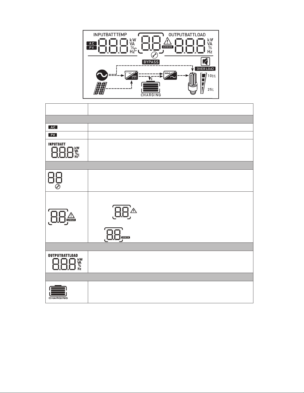
LCD Display Icons
Icon Function description
Input Source Information
Indicates the AC input.
Indicates the PV input
Indicate input voltage, input frequency, PV voltage, battery voltage and
charger current.
Configuration Program and Fault Information
Indicates the SURJUDPVHWWLQJV
Indicates the warning and fault codes.
Warning: flashHVWKH warning code.
Fault: lightVWKH fault code
Output Information
IndicateVWKH output voltage, output frequency, load percentDJH,loadin
VA, load in Watt and dischargHcurrent.
Battery Information
Indicates battery level0-24%, 25-49%, 50-74% and 75-100% IRUHDFKEDU
LQ battery mode and charging status in line mode.

17
Load Information
Indicates overload.
Indicatestheloadlevel0-24%,25-49%,50-74%and75-100%.
0%~24% 25%~49% 50%~74% 75%~100%
Mode Operation Information
IndicatesunitLVFRQQHFWHGWRWKHJULG.
IndicatesunitLVFRQQHFWHGtothePVpanel.
IndicatesloadisGLUHFWO\FRQQHFWHGWRWKHJULG
IndicatestheutilitychargercircuitisRSHUDWLRQDO.
IndicatestheDC/ACinvertercircuitisRSHUDWLRQDO.
Mute Operation
Indicates unit alarm is disabled.
18
ProgramSetting
AfterpressingandholdingWKHE
ENTER
buttonfor3seconds,theunitwillentersettingmode.Press
UP
or
DOWN
buttontoselectsettingprograms.7hen,press
ENTER
buttontoconfirmtheselectionor
ESC
buttontoexit.
SettingPrograms:
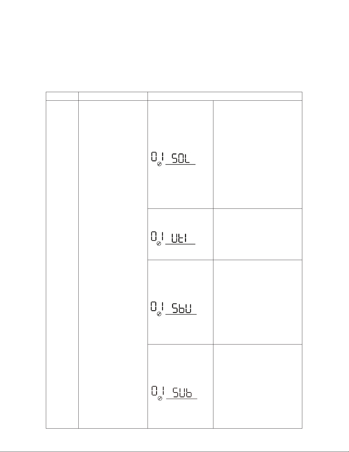
Program Description Selectable option
01 Output source priority: To
configure load power
source priority
Solar first
Solarenergyprovidespowerto
theloadsasfirstpriority.
Ifsolarenergyisnotsufficientto
powerallconnectedloads,battery
energywillsupplypowerWRthe
loadsatthesametime.Utility
providespowertotheloadsonly
whenoneRUDOO RI WKHIROORZLQJ
conditionVLVLQSOD\:
-
Solarenergyisnotavailable
-
Batteryvoltagedropstoeither
low-levelwarningvoltageorthe
settingpointin
program
12.
Utility first (default)
Utility will provide power to the
loads as first priority.
Solar and battery energy will
provide power to the loads only
when utility power is not
available.
SBU priority
Solar energy provides power to
the loads as first priority.
If solar energy is not sufficient to
power all connected loads, battery
energy will supply power to the
loads at the same time.
Utility provides power to the loads
only when battery voltage drops to
either low-level warning voltage or
the setting point in program 12.
SUB priority
Solarenergyischargedfirstand
thenpowertotheloads.
Ifsolarenergyisnotsufficientto
powerallconnectedloads,Xtility
energywillsupplypowertothe
loadsatthesametime.
Other manuals for 3000 EHV-48
1
Table of contents
Other EG4 Inverter manuals


Popular Inverter manuals by other brands


BARRON
BARRON EXITRONIX Tucson Micro Series installation instructions

Baumer
Baumer HUBNER TDP 0,2 Series Mounting and operating instructions

electroil
electroil ITTPD11W-RS-BC Operation and Maintenance Handbook

Silicon Solar
Silicon Solar TPS555-1230 instruction manual

Mission Critical
Mission Critical Xantrex Freedom SW-RVC owner's guide

HP
HP 3312A Operating and service manual


