4
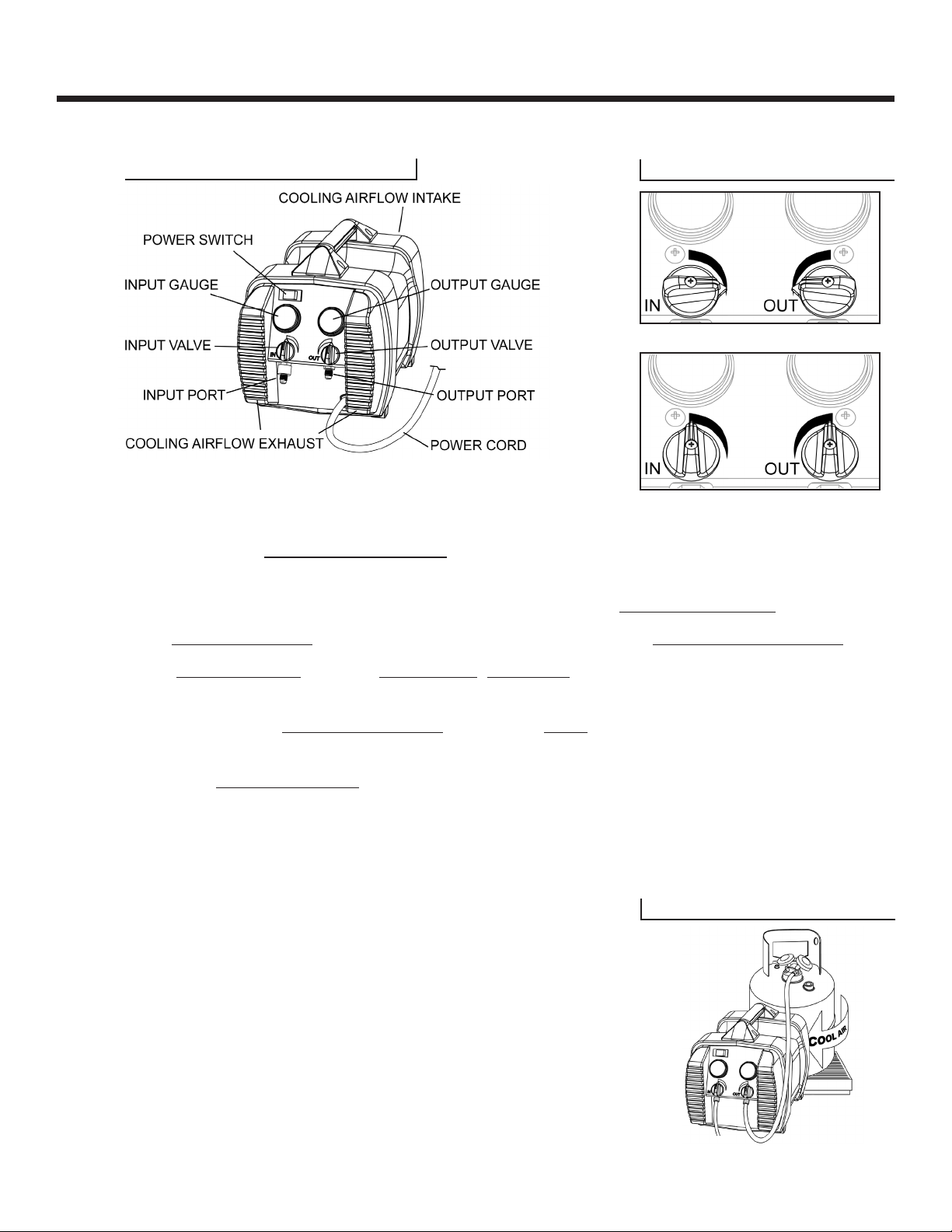
G5TWIN OPERATION MANUAL
© 2022 APPION INC. - ALL RIGHTS RESERVED
HAZARD: RISK OF EXPLOSION OR FIRE
⚠DANGER
Use of this equipment may pose certain explosion and fire hazards.
WHAT CAN HAPPEN HOW TO PREVENT IT
Flammable/combustible gases and air may become
unknowingly ingested through leaks in hoses,
gaskets, connections or leaking seals, leading to
compression of these gases. Air and hydrocarbons,
if pumped to a tank, create an explosive mixture
that random static electricity could ignite.
Do not use in the vicinity of spilled or open
containers of gasoline, propane, butane, acetylene,
or other flammable gases.
Do not use near open sewer lines which may be
emitting sewer gases.
Flammable substances may ignite or explode when
compressed in certain situations.
Do not use this machine to pump hydrocarbons,
including blends containing butane, isobutane, or
propane. Hydrocarbons are flammable substances
and may ignite or explode when compressed in
certain situations.
Improper use of extensions cords may result in
overheating or fire in the cord or machine.
Use only 12AWG or 10AWG extension cords:
- Up to 25 Feet: 12/3 UL/CSA cord
- Up to 100 Feet: 10/3 UL/CSA cord
Warnings and Safety Information(continued)
A3 REFRIGERANT DANGER
Do not use this machine to pump hydrocarbons, including A3 refrigerants.
While most refrigerant recovery machines on the market are able to pump hydrocarbon refrigerants such as
propane and butane, none of them can do so safely without creating an explosion hazard in the tank.
A significant risk inherent with the recovery of hydrocarbon refrigerants is the potential to accidentally
ingest air and pump this air into a tank with hydrocarbons. This compressed hydrocarbon and air mixture
within the tank can create an explosion hazard. The accidental ingestion of air can come from many
scenarios. These scenarios include but are not limited to faulty system components, improper system
installation, improperly purged recovery hoses, worn hose gaskets, and worn recovery machine compressor
components.
Industries that work with hydrocarbons avoid these risks by constantly venting air and hydrocarbon vapors
while transferring in a pure liquid-only state. The transfer process only stops once the liquid hydrocarbon
begins to spray out of the vent port of the receiving tank. This transfer process is the only way to make sure
no air or other non-condensables are in the receiving tank.
The procedure explained above is not possible to perform when pumping hydrocarbon vapor with a recovery
machine. Since there is no safe way to totally eliminate air being ingested during the recovery process,
pumping hydrocarbons with any recovery machine should not be done under any circumstance.
⚠DANGER