2440 Ser ice
LIST OF ILLUSTRATIONS
Figure Page
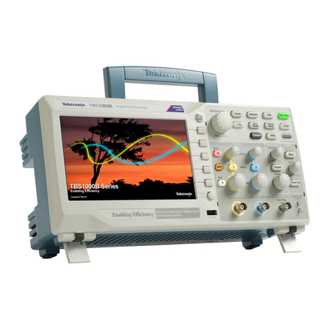
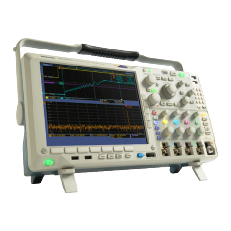
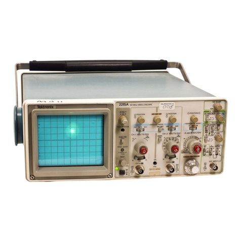
The 2440 Digital Oscilloscope.................................................................................................................. iii
1- 1 Dimensional drawing................................................................................................................................... 1-24
2- 1 LINE VOLTAGE SELECTOR, line fuse, and power cord receptacle
...............................................
2-1
3- 1 2440 simplified block diagram.................................................................................................................... 3-3
3-2 Simplified Memory Map of the 2440........................................................................................................ 3-18
3-3 System Clock wa eforms............................................................................................................................3-37
3-4 Simplified Peak Detector block diagram................................................................................................. 3-47
3-5 Simplified CCD architecture.........................................................................................................................3-49
3-6 Trigger Logic Array Control Data Byte.................................................................................................. 3-53
3-7 Jitter correction wa eforms........................................................................................................................ 3-57
3-8 Readout State Machine flow chart........................................................................................................... 3-71
3-9 Vertical Vector Generator............................................................................................................................3-73
3-10 DC Restorer.................................................................................................................................................... 3-78
3-11 GPIB data flow diagram................................................................................................................................3-81
3-12 GPIB three-wire handshake state diagram............................................................................................ 3-82
3-13 Video Option wa eforms...............................................................................................................................3-87
3-14 Video Option field-sync identification....................................................................................................... 3-88
3-15 PWM Regulator and In erter.......................................................................................................................3-94
3-16 PWM switching wa eforms.......................................................................................................................... 3-96
5-1 Adjustment locations for Displays 4 through 6 ..................................................................................... 5-4
5-2 Display 5— Vertical and Horizontal Gain, Offset, and Vector
Compensation adjustment pattern......................................................................................................... 5-5
5-3 Display 6— Integrator Time adjustment pattern.................................................................................... 5-6
5-4 (SN B010250 & Abo e) CH 1 and CH 2 CCD Clock Adjustments
(shown centered, as after doing part b)................................................................................................ 5-7
5-4 (SN B010249 & Below) CH 1 and CH 2 CCD Clock Adjustments
(shown centered, as after doing part b )................................................................................................ 5-8
5-5 CCD counts display and CM adjustment menu.................................................................................... 5-8
5-6 CCD sides 1 -4 for CH 1 before L-clock adjustment............................................................................. 5-12
5-7 Sides 1 and 3 before adjustment of LIS and after
..............................................................................
5-13
5-8 CH 1 with L-clocks correctly adjusted, but with stray samples
........................................................
5-14
5-9 Display for adjusting CCD A and T clocks............................................................................................. 5-15
5-10 Typical CH 1 and CH 2 displays after clock adjustment.................................................................... 5-16
5-11 Checking sample dispersion...................................................................................................................... 5-17
5- 12 Input and output (after adjustment) wa eforms.................................................................................... 5-20
6- 1 Multipin connector........................................................................................................................................ 6-8
6-2 Circuit board Location.................................................................................................................................. 6-16
6-3 Installation sequence for installing the crt frame screws
....................................................................
6-23
6-4 Trigger LED binary coding for diagnostic tests..................................................................................... 6-29
6-5 Main EXT DIAG Menu.................................................................................................................................. 6-30
6-6 Initial troubleshooting chart......................................................................................................................... 6-36
6-7 Mux Test wa eforms................................................................................................................................... 6-41
REV SEP 1988 ®
