TECPEL CL 325 User manual

Multifunction Calibrator
Model CL 325
CALIBRATOR
PROCESS
ENTER
0-24mA
K J E T
7
.
%
_%
%
8
0
4-20mA
mV 1V
12V
4
1
C F
0-20mA
5°
2
Hz
mV
V
9
°C
°F
mA
SHIFT
ON/OFF
6
3
-+
TC
-
+
+
-
°
TECPEL CO., LTD.

Features:
1. 4-20mA (1KΩload, 24V Loop Supply)
2. 0-100.00mV,0-1.000V, 0-12.000V
3. K, J, E, T Thermocouple (°C and °F)
4. Frequency 1-62500 Hz
5. 0.025% Basic Accuracy
6. Easy Key-pad Operation
7. Easy Step and Auto Ramp Functions
8. 0-20mA, 0-24mA selectable
9. 0-100% Input (mA, mV, V )
10. Beeper warning when output is open (mA) or short (mV,V)

Table of Contents
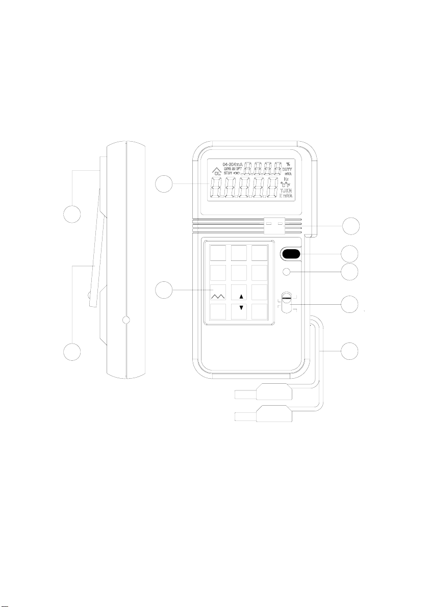
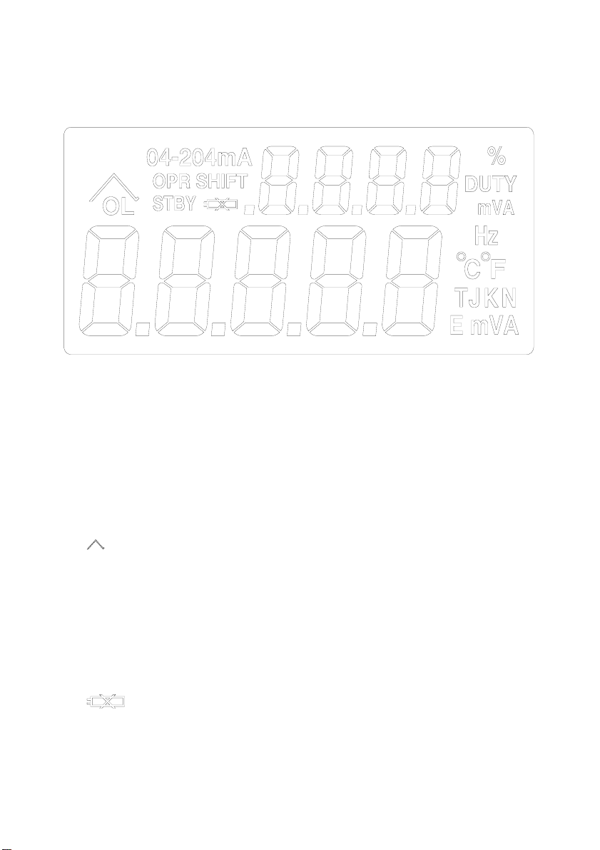
I. PANEL DESCRIPTION..............................................................................................................1
II. OPERATING INSTRUCTION.................................................................................................6
1. MA OUTPUT.................................................................................................................................6
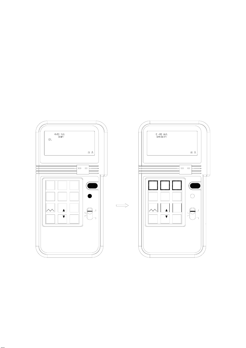
1a. General Operation 4 - 20mA........................................................................................6
1b. Select 0 - 20mAor 0 - 24mA........................................................................................7
1c. Enter a value less than 1................................................................................................8
2. MV, V OUTPUT........................................................................................................................9
2a. General Operation 0 - 100mV......................................................................................9
2b. Select 0 - 1V or 0 - 12V................................................................................................10
2c. Enter a value less than 1..............................................................................................11
3. HZ, FREQUENCYOUTPUT......................................................................................................12
4a. General Operation.........................................................................................................13
4b. Select °C, or °F...........................................................................................................15
4c. Select K, J, E, or Ttype Thermocouple................................................................17
4d. Enter a Negative Temperature...................................................................................18
5. % INPUT IN THE MA, MV, V FUNCTIONS...............................................................................19
6. EASYSTEP INTHE MA, MV, AND V FUNCTIONS .................................................................21
7.AUTO RAMP INTHE MA, MV, AND V FUNCTION...................................................................23
8. HOW TO GETNEGATIVE OUTPUT .........................................................................................26
III. ELECTRICAL SPECIFICATION.........................................................................................27
IV. USE THEACADAPTER.......................................................................................................32
V. USE EXTERNAL BATTERY PACK...................................................................................33
VI. BATTERY REPLACEMENT................................................................................................34

I. Panel Description
7
8
1
K J E T
0-24mA
ENTER
PROCESS
CALIBRATOR
6
_
%
.
7
0
8
%
%
mV 1V
4-20mA
1
4
12V °
2
°
5
0-20mA
C F
9V
mV
Hz
mA
F
°C
°
5
ON/OFF
SHIFT
3
6
TC+
-
4
3
2
9
1.LCD DISPLAY 6. NUMERICAL & FUNCTION KEYPAD
2.THERMOCOUPLE SOCKET 7. STAND
3.ON/OFF BUTTON 8. AC ADAPTOR INPUT SOCKET
4.SHIFT BUTTON 9. OUTPUT LEADS
5.FUNCTION SELECT SWITCH
1

1.mVAHz: Units
2.04-204mA : Range of mA
3.%: Percentage
4.JKET: Thermocouple type
5. : Ramp
6.OPR : Operate, Output, Normal
7.OL: Overload, Output, Abnormal
8.STBY: Standby, Internal Calibration in Progress
9.SHIFT: Select SHIFT functions
10. : Battery low
2

12V
4-20mA
mV 1V
7
.
%
C F
0-20mA
8
_%
%
0
45°°
ENTER
9
0-24mA
K J E T
6
123
4-20mA 0-20mA 0-24mA
123
1
.
Press SHIFT button, and then press one of these three buttons to select desired mA
range
2.
mV 1V
12V
4
Press SHIFT button, then press this button to select desired mV or V range
3

3.
C F
°°
5
Press SHIFT button, then press this button to select °C or °F
4.
K J E T
6
Press SHIFT button, then press this button to select desired type of thermocouple.
5. 7
Press SHIFT button, then press this button to perform auto-ramp function. To stop
the auto-ramp function, press this button again
6.
4
%
.
_

Press this button to enter negative temperature. Or press SHIFT button, then press
this button first to enter percentage in the mA, mV, and V functions.
0
%
8
%
7.
While the calibrator is in the SHIFT mode, and the percentage is entered, press this
button to increment %.
8.
ENTER
Always press this button to complete the entry of numbers.
II. Operating Instruction
1. mA Output
1a. General Operation 4 - 20mA
1 Turn the power on, and wait until the STBY symbol disappears (about 1
5

min.)
2 Plug the test leads into the output connectors of calibrator accordingly
(Black to black, red to red). Attach alligator clip if necessary.
3 Move the sliding switch to mA position
4 Press the keypad (including the decimal point) to enter the value of mA
directly.
5 Using the test leads or alligator clips, touch or clip on the terminals to be
calibrated.
312
CALIBRATOR
0-24mA
ENTER
PROCESS
%
_
.
%%
0
4
12V
mV 1V
4-20mA
7
°
5
0-20mA
C F
8
Hz °C
°F
SHIFT
6
V
mV
9
K J E T
mA
ON/OFF
+
-TC
8.000mA
°
Note: Always waits until STBY (standby) symbol in the LCD disappears before
any operation.
Note: Maximum 5 digits can be entered. If users enter less than 5 digits (1 to 4
digits), users must press ENTER button to indicate the end of entry. If users
enter 5 or more digits, calibrator will automatically end the entry and output
specified value current.
6

1b. Select 0 - 20mA or 0 - 24mA
The default setting for mA function is 4 - 20mA. But users can select 0 - 20mA or 0
-24 mA by pressing the SHIFT button to enter the SHIFT mode. Then press the
NUMBER 2 or NUMBER 3 button to select desired DC current range. After desired
range is selected, press the shift button to exit the SHIFT mode. Corresponding
current range symbol will be displayed in the LCD.
mV 1V
0-24mA
K J E T
CALIBRATOR
PROCESS
ENTER
%
%
.
_0
%
21
4-20mA
7
mV 1V
12V
4
0-20mA
8
C F
5°
Hz
F
°C
°
3
SHIFT
9mV
V
6
mA
ON/OFF
TC
-+
%
CALIBRATOR
PROCESS
0
%
.
_%ENTER Hz
F
°C
°
mV
ON/OFF
+
78
12V
45°C F
9V
6
K J E T
-TC
SHIFT
mA
° °
3
0-24mA
2
0-20mA
1
4-20mA
7

ENTER Hz
.
_%
PROCESS
CALIBRATOR
%0F
°C
°
C F
0-20mA
12V
4
mV 1V
7
°°
5
%
8
4-20mA
12 ON/OFF
SHIFT
K J E T
6
9V
mV
-
0-24mA
3
+
TC
mA
1c. Enter a value less than 1
In the mA functions, the standard way to enter a value less than 1 is to press leading
0 before pressing the decimal point. Though the decimal point can be entered, the
decimal point will not be shown in the LCD.
8

2. mV, V Output
2a. General Operation 0 - 100mV
1. Turn the power on, and wait until the STBY symbol disappears (about 2
min.).
2. Plug the test leads into the output connectors of calibrator accordingly
(Black to black, red to red). Attach alligator clip if necessary.
3. Move the sliding switch to mV, V position
4. Press the keypad (including the decimal point) to enter the value of mA
directly.
5. Using the test leads or alligator clips, touch or clip on the terminals to be
calibrated.
mV
%
ENTER
PROCESS
CALIBRATOR
_
.
%%
0Hz °C
°F
0-24mA
12
4
12V
mV 1V
4-20mA
7
°
5
0-20mA
C F
8
3
SHIFT
6
V
9
K J E T
mA
ON/OFF
+
-TC
REDBLACK
°
100.00mV
Note: Always wait until STBY (standby) symbol in the LCD to disappear before
any operation.
Note: Maximum 5 digits can be entered. If users enter less than 5 digits (1 to 4
digits), users must press ENTER button to indicate the end of entry. If users
enter 5 or more digits, calibrator will automatically end the entry and output
specified value current.
9

2b. Select 0 - 1V or 0 - 12V
The default setting for mV, V function is 0 - 100.00mV. Users can select 0 -
1.0000V or 0 -12.000V by pressing the SHIFT button to enter SHIFT mode.
Then press the NUMBER 4 button repeatedly to select desired DC voltage
range. After desired range is selected, press the SHIFT button again to exit the
SHIFT mode. Corresponding voltage range symbol will be displayed in the
LCD.
4-20mA
ENTER
PROCESS
CALIBRATOR
K J E T
0-24mA
5
mV 1V
12V
7
%
.
_
C F
°
8
%
0
%
4-20mA
4
10-20mA
2
6
V
Hz
9mV mA
°C
°F
-+
ON/OFF
SHIFT
TC
3
65
mV
CALIBRATOR
PROCESS
8
C F
7
°°
%
_0
%
.
%
K J E T
V
Hz
ENTER
9mA
C
°F
°
+
ON/OFF
-
2
0-20mA
1
TC
0-24mA
3
SHIFT
°12V
mV 1V
4
10

SHIFT
65
4C F
CALIBRATOR
PROCESS
%
.
_
%0
mV 1V
7
12V °
8
%
°
ENTER Hz
K J E T
9V
mV
°F
°C
mA
0-20mA4-20mA
12 ON/OFF
+
-
3
0-24mA
TC
2c. Enter a value less than 1
In the mV/V functions, the standard way to enter a value less than 1 is to press
the leading 0 before pressing the decimal point. Though the decimal point can
be entered first, the decimal point will not be shown in the LCD.
11

3. Hz, Frequency Output
1. Turn the power on, then plug the test leads into the output connectors of
calibrator accordingly (Black to black, red to red). Attach alligator clip if
necessary.
2. Move the sliding switch to Hz position
3. Press the keypad (excluding the decimal point) to enter the value of Hz
directly.
4. Using the test leads or alligator clips, touch or clip on the terminals to be
calibrated.
5.Because not all the frequencies are available between 126 to 62500Hz,
calibrator will automatically adjust and display the users input value to a
frequency, which is available and always larger or equal to users input.
0-20mA 0-24mA4-20mA
C F
PROCESS
CALIBRATOR
%
0
.
_
%
°
5
%
8
4
12V
7
mV 1V
Hz
ENTER C
°F
°
mV
6
9
K J E T
SHIFT
mAV
12
TC
-
3
+
ON/OFF 25000Hz
°
Note: The resolution of Hz function is 1 Hz. For the range 1-125Hz, all the
frequencies in between are available. But for the range 126 - 62500Hz, not all
the frequencies are available (total 604 frequencies available). Please refer to
section III Electrical Specifications for available frequencies.
12

4. Thermocouple Calibration of °C, °F.
4a. General Operation
1.Turn the power on, and wait until the STBY symbol disappears (about 1
min.).
2.Plug the corresponding connector (K-type connector for K-type
thermocouple, J-type connector for J-type thermocouple, ...) into TC
terminals of calibrator and thermometer to be calibrated.
3.Move the sliding switch to °C, °F position
4.Press the keypad (including the minus - button) to enter the value of
Temperature directly.
321 0-20mA
C F
CALIBRATOR
PROCESS
%
.0
%
_%
5
4
mV 1V
4-20mA
87
12V °
Hz
ENTER F
°C
°
mV
6
0-24mA
9
K J E T
mAV
SHIFT
TC
-+
ON/OFF
+
-
+
-
-+
°
100.0° C
13

312
CALIBRATOR
0-24mA
ENTER
PROCESS
%
_
.
%%
0
4
12V
mV 1V
4-20mA
7
°
5
0-20mA
C F
8
Hz °C
°F
SHIFT
6
V
mV
9
K J E T
mA
ON/OFF
+
-TC
100.0°C
°
Note: Users can plug the connector into the TC terminals of calibrator even
before the power is turned on for better thermal equilibrium between the TC
terminal and thermocouple connector.
Note: Only in the °C and °F functions, the negative values are allowed to be
entered. To enter negative temperature, press the minus"-" button first.
Note: Maximum 4 digits (including the "-" sign) can be entered.
If users enter less than 4 digits (1 to 3 digits), users must press
ENTER button to indicate the end of entry. If users enter 4 or
more digits, calibrator will automatically end the entry and output
specified value of temperature.
14

4b. Select °C, or °F
Users can select °C or °F by pressing the shift button to enter SHIFT mode. Then
press the NUMBER 5 button repeatedly to select desired temperature unit. After
desired unit is selected, press the SHIFT button again to exit the SHIFT mode.
Corresponding voltage °C or °F symbol will be displayed in the LCD.
mV 1V
4-20mA0-24mA
K J E T
CALIBRATOR
PROCESS
ENTER
.
%
7
_
%
0
%
8
1
4
mV 1V
4-20mA
12V
2
5
0-20mA
°C F
mV
9
Hz
V
F
°C
°
mA
SHIFT
ON/OFF
3
6
+
-TC
CALIBRATOR
PROCESS
ON/OFF
%
.
%0
_%
789
ENTER
1
12V
0-20mA
2
4
3
0-24mA
6
K J E T
SHIFT
+
-TC
°5
C F°°
°
°
Hz
F
C
mAV
mV
15

87
PROCESS
CALIBRATOR
0
%
_
.%
%9
ENTER
0-20mA
C F
4-20mA
12V
mV 1V
4°°
5
12
+
-
ON/OFF
0-24mA
K J E T
6SHIFT
3
TC
°
°
Hz C
F
mAV
mV
16

4c. Select K, J, E, or T type Thermocouple
Users can select K, J, E, or T type Thermocouple by pressing the shift button to
enter SHIFT mode. Then press the number 6 button repeatedly to select desired
type of thermocouple. After desired type is selected, press the shift button again to
exit the SHIFT mode. Corresponding thermocouple type (K, J, E, or T) symbol will
be displayed in the LCD.
mV 1V
4-20mA0-24mA
K J E T
CALIBRATOR
PROCESS
ENTER
.
%
7
_
%
0
%
8
1
4
mV 1V
4-20mA
12V
2
5
0-20mA
°C F
mV
9
Hz
V
F
°C
°
mA
SHIFT
ON/OFF
3
6
+
-TC
CALIBRATOR
PROCESS
ON/OFF
%
.
%0
_%
789
ENTER
1
12V
0-20mA
2
4
3
0-24mA
6
K J E T
SHIFT
+
-TC
°5
C F
°°
°
°
Hz
F
C
mAV
mV
17
Table of contents
Other TECPEL Test Equipment manuals
Popular Test Equipment manuals by other brands

Tektronix
Tektronix MSO70000C Series user manual

Keysight Technologies
Keysight Technologies 16047A Operation and service manual

Agilent Technologies
Agilent Technologies 1000B Series user guide

CharlesWater
CharlesWater 99090 Installation, operation and maintenance guide

Fluke
Fluke 714 instruction sheet

BIRD
BIRD AT-800 Operation manual