APPLIED ACOUSTICS Dura-Spark L80 User manual

Dura-Spark L80
Operation Manual

Dura-Spark L80 Operation Manual
SPK-L80-8000/A
__________________________________________________________________________________________________________
___________________________________________________________________________________________________________
Page 2of 20
Revision History
Issue
Change
No.
Reason for change
Date
A
-
Draft
03/09/20

Dura-Spark L80 Operation Manual
SPK-L80-8000/A
__________________________________________________________________________________________________________
___________________________________________________________________________________________________________
Page 3of 20
Table of Contents
REVISION HISTORY .......................................................................................................................................... 2
1. INTRODUCTION TO THE DURA SPARK SOUND SOURCE..................................................................... 5
2. COMPONENTS......................................................................................................................................... 6
3. THEORY OF OPERATION ......................................................................................................................... 6
4. DURA SPARK L80 POWER LEVELS.......................................................................................................... 6
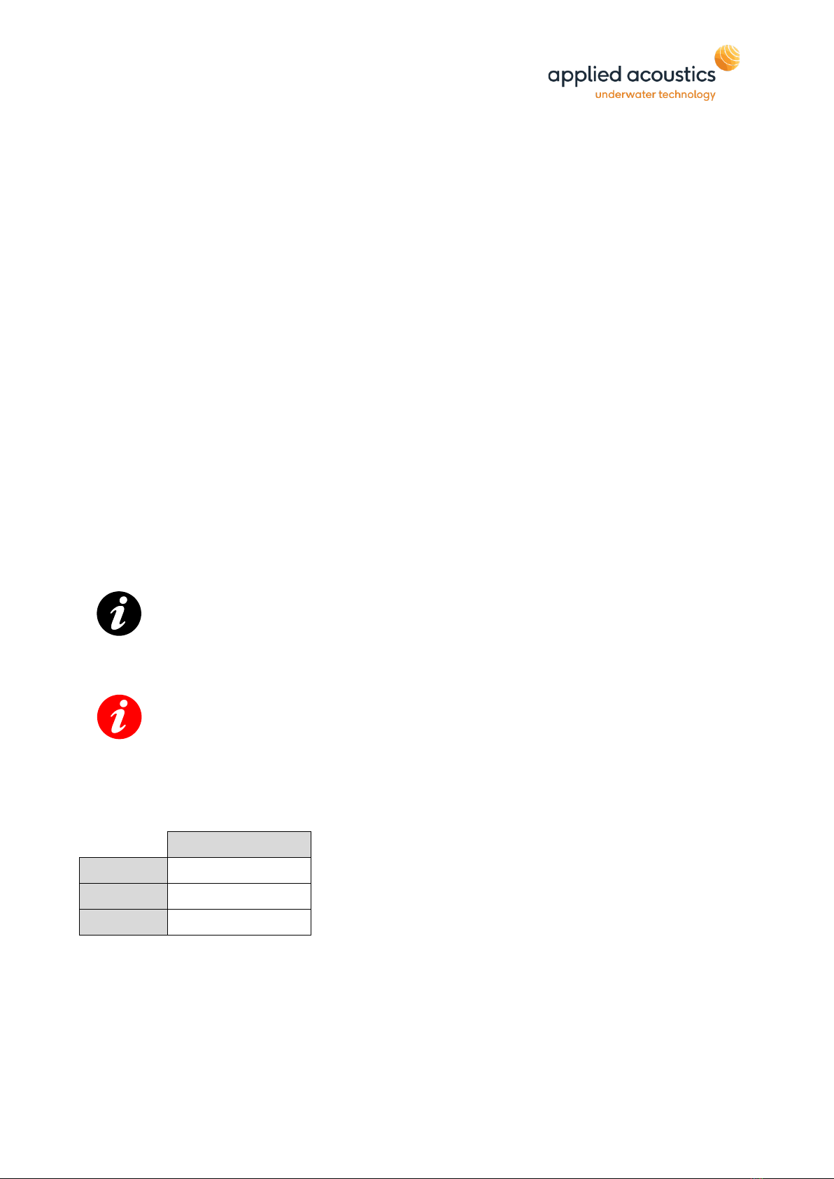
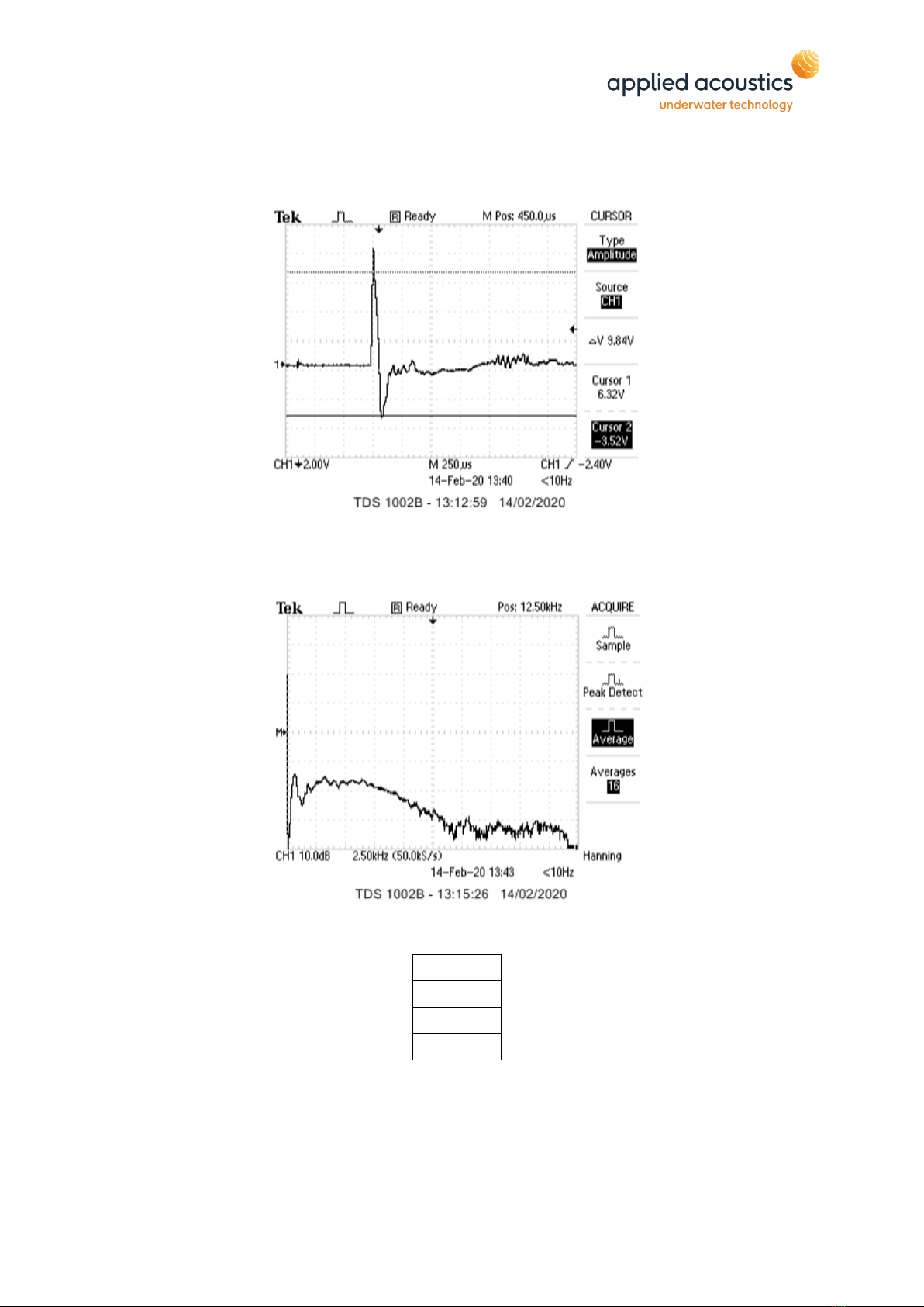
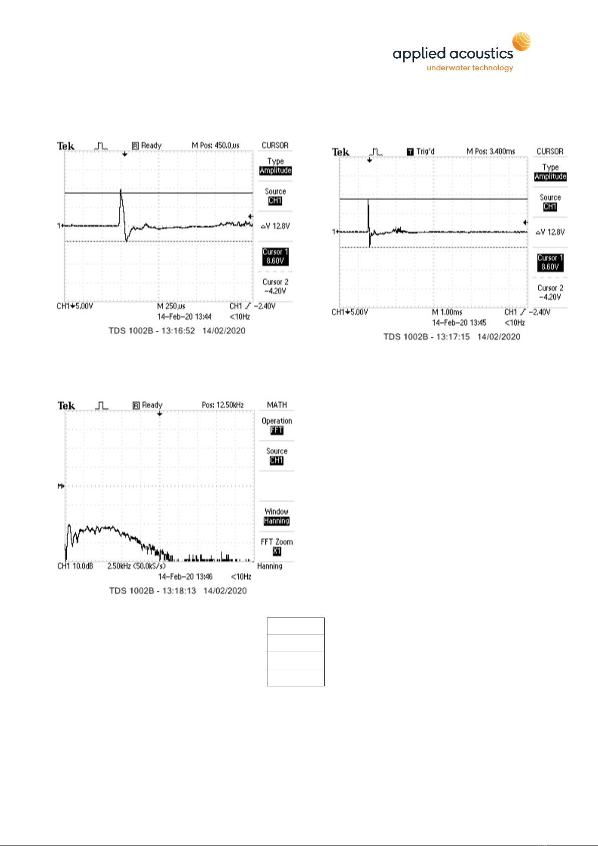
5. PULSE SIGNATURE................................................................................................................................... 7
100J................................................................................................................................................................ 7
200J............................................................................................................................................................... 8
300J............................................................................................................................................................... 9
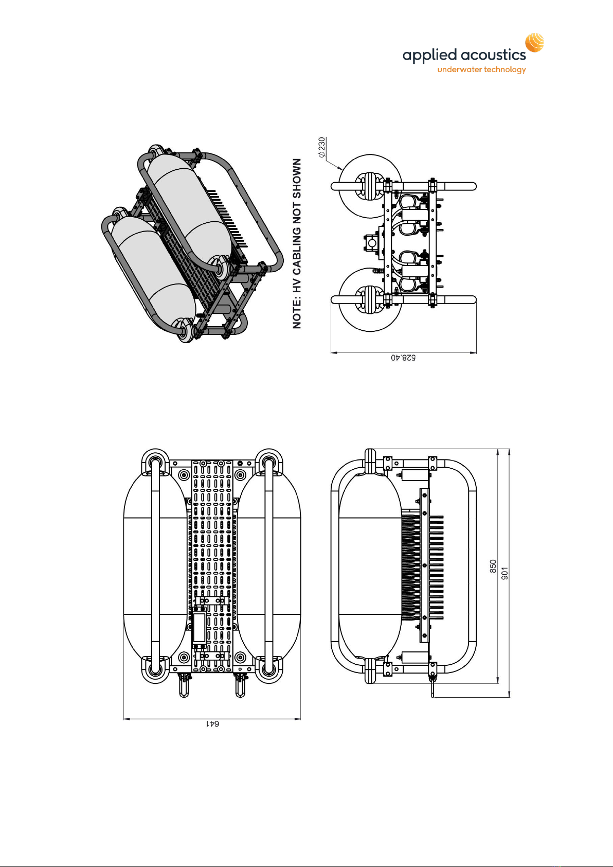
6. DIMENSIONS.......................................................................................................................................... 10
7. CABLING AND CONNECTIONS ............................................................................................................ 11
HVJ2001 JUNCTION BOX LAYOUT AND CONNECTIONS........................................................................................ 11
HVJ3001 JUNCTION BOX LAYOUT .................................................................................................................... 11
HVJ3001 JUNCTION BOX BUZZ BAR ARRANGEMENT ........................................................................................... 12
DURA SPARK 80 -40 TIP ARRANGEMENT........................................................................................................... 12
DURA SPARK 80 -80 TIP ARRANGEMENT........................................................................................................... 13
HVJ3000 JUNCTION BOX INTERLOCK WIRING ................................................................................................... 14
HVC2002 CABLE........................................................................................................................................... 15
8. DEPLOYMENT / INSTALLATION ............................................................................................................ 16
9. MAINTENANCE PROCEDURES.............................................................................................................. 17
TIP WEAR........................................................................................................................................................ 17
MECHANICAL .................................................................................................................................................. 17
10. END OF LIFE RECYCLING / DISPOSAL .................................................................................................. 17
11. SPECIFICATION ..................................................................................................................................... 18
PHYSICAL........................................................................................................................................................ 18
ELECTRICAL SPECIFICATION ............................................................................................................................... 18
COMPATIBILITY ................................................................................................................................................ 18
PERFORMANCE ................................................................................................................................................ 18

Dura-Spark L80 Operation Manual
SPK-L80-8000/A
__________________________________________________________________________________________________________
___________________________________________________________________________________________________________
Page 4of 20
Thank you for choosing applied acoustics ltd as one of your equipment suppliers. We
hope you experience many years of reliable operational use from our products.
modulus technology ltd carries out all technical support, servicing and repairs. If you
have any technical issues with our products please contact the modulus technology
team:
Tel: +44 (0)1493 416452
Email: techsupport@modulustechnology.com
Web: modulustechnology.com
Applied Acoustic Engineering Ltd has made every effort to ensure that the information
contained in this manual is correct at time of print. However our policy of continual product
improvement means that we cannot assume liability for any errors which may occur.
These written instructions must be followed fully for reliable and safe operation of the
equipment that this manual refers to. Applied Acoustic Engineering Ltd cannot be held
responsible for any issues arising from the improper use or maintenance of equipment
referred to in this manual or failure of the operator to adhere to the instructions laid out in
this manual. The user must be familiar with the contents of this manual before use or
operation.

Dura-Spark L80 Operation Manual
SPK-L80-8000/A
__________________________________________________________________________________________________________
___________________________________________________________________________________________________________
Page 5of 20
1. Introduction to the Dura Spark Sound Source
The Dura-Spark has been designed to provide a stable, repeatable sound source for
sub-bottom geophysical surveys. The long life, durable electrodes produce a
consistent pulse signature and keep operational maintenance to a minimum. This
provides increased survey efficiency and equipment reliability as the sparker tips
rarely need replacement.
The Dura-Spark L80 is based on the CAT100 catamaran, providing a stable platform
whilst under tow. The Dura-Spark L80 consists of 2 arrays of 40 tips forming a single
array of 80 tips, providing a powerful high resolution sound source.
The typical operational bandwidth of the Dura-Spark L80 is 500Hz to 5KHz. When
coupled with the CSP-Nv Seismic Power Supply the system offers 2000J/s peak
discharge rate, as well as industry leading design and safety standards.

Dura-Spark L80 Operation Manual
SPK-L80-8000/A
__________________________________________________________________________________________________________
___________________________________________________________________________________________________________
Page 6of 20
2. Components
•Dura Spark Catamaran complete with 2 x40 Tip Long Life Sparker Arrays.
•HVC2002 High Voltage Cable complete with HVJ2001 Junction Box.
3. Theory of Operation
The sound wave is generated by the electrical energy in the capacitors of the
CSP-Nv discharging across the sparker tips to the earth of the tow-body, through
the sea water to produce a pressure wave.
With increased energy levels a secondary discharge pulse is generated after the
initial discharge. The time delay between initial and secondary is proportional to
the level of energy being discharged. The secondary pulse is commonly known
as the ‘bubble pulse’.
The joule per tip rating should not be exceeded, each sparker tip is rated to 8-
10joule maximum. This is a total max power of 350joule. Exceeding this level will
result in damage to the sparker tip.
Note: - To prevent the bubble pulse the tip to power ratio should not exceed
2-3J per tip.
The joule per tip rating should not be exceeded, each sparker tip is rated to
8-10joule maximum. This is a total max power of 350joule. Exceeding this
level will result in damage to the sparker tip.
4. Dura Spark L80 Power Levels
80 Tips
Min
100J
Max
350J
Typical
200J

Dura-Spark L80 Operation Manual
SPK-L80-8000/A
__________________________________________________________________________________________________________
___________________________________________________________________________________________________________
Page 7of 20
5. Pulse Signature
100J
Pulse Width =
250
uSec
V peak to peak =
6.28
V
Source Level =
1.08837
V/Bar
At 1M
220.736
dB re 1.0V/uPa
At 1M

Dura-Spark L80 Operation Manual
SPK-L80-8000/A
__________________________________________________________________________________________________________
___________________________________________________________________________________________________________
Page 8of 20
200J
Pulse Width =
250
uSec
V peak to peak =
9.84
V
Source Level =
1.70534
V/Bar
At 1M
224.636
dB re 1.0V/uPa
At 1M

Dura-Spark L80 Operation Manual
SPK-L80-8000/A
__________________________________________________________________________________________________________
___________________________________________________________________________________________________________
Page 9of 20
300J
Pulse Width =
250
uSec
V peak to peak =
12.8
V
Source Level =
2.21833
V/Bar
At 1M
226.921
dB re 1.0V/uPa
At 1M

Dura-Spark L80 Operation Manual
SPK-L80-8000/A
__________________________________________________________________________________________________________
___________________________________________________________________________________________________________
Page 10 of 20
6. Dimensions

Dura-Spark L80 Operation Manual
SPK-L80-8000/A
__________________________________________________________________________________________________________
___________________________________________________________________________________________________________
Page 11 of 20
AAE REFERENCE - HVJ-3001-7000/2
HV CABLE
FROM CSP HV3500
CABLE
2
2
7. Cabling and Connections
HVJ2001 Junction Box Layout and Connections
HVJ3001 Junction Box Layout

Dura-Spark L80 Operation Manual
SPK-L80-8000/A
__________________________________________________________________________________________________________
___________________________________________________________________________________________________________
Page 12 of 20
HVJ3001 Junction Box Buzz Bar Arrangement
Before attempting to configure the HV3001 junction box with any of the following
arrangements, ensure that all HV equipment is turned off and the HV cable from the
CSP unit is disconnected.
Please note that the two bottom right studs are not common connections and must be
used to store the HV buzz bars when not in use.
Dura Spark 80 - 40 Tip Arrangement
Connect the Red Live terminal to the Red lead of the HVC-2002, Yellow
terminal to the yellow lead (not in circuit) and the Black GND terminal to
the Black lead of the HVC-2002.
The Blue Terminal is not used with the Dura Spark L80.

Dura-Spark L80 Operation Manual
SPK-L80-8000/A
__________________________________________________________________________________________________________
___________________________________________________________________________________________________________
Page 13 of 20
Dura Spark 80 - 80 Tip Arrangement
Connect the Red Live terminal to the Red lead of the HVC-2002, Yellow
terminal to the yellow lead and the Black GND terminal to the Black lead of
the HVC-2002.
The Blue Terminal is not used with the Dura Spark L80.

Dura-Spark L80 Operation Manual
SPK-L80-8000/A
__________________________________________________________________________________________________________
___________________________________________________________________________________________________________
Page 14 of 20
MICRO SWITCH
JUNCTION BOX CABLE
TO CSP
HV3500 CABLE
COM. NO
AAE REFERENCE - HVJ-3000-4000/1
HVJ3000 Junction Box Interlock Wiring
Note: When used with the Dura Spark the subsea interlock is by-passed
using the link provided.

Dura-Spark L80 Operation Manual
SPK-L80-8000/A
__________________________________________________________________________________________________________
___________________________________________________________________________________________________________
Page 15 of 20
HVC2002 Cable

Dura-Spark L80 Operation Manual
SPK-L80-8000/A
__________________________________________________________________________________________________________
___________________________________________________________________________________________________________
Page 16 of 20
8. Deployment / Installation
The towing bridle should be secured to the catamaran using two stainless
shackles on the two lower tow points and connected to the HV Cable Grip.
The cable tow point should be adjusted so that no load is applied to the
electrical connections or cable clamp.
A quick sea trial should be undertaken to check the floatation / towing
characteristics of the catamaran underway at roughly 3-5 Knots.
Note: No stress should be applied to the electrical connections whilst the
unit is undertow as this may cause failure during operation.

Dura-Spark L80 Operation Manual
SPK-L80-8000/A
__________________________________________________________________________________________________________
___________________________________________________________________________________________________________
Page 17 of 20
9. Maintenance Procedures
Tip Wear
Although Sparker tip wear is very low the sparker tips should be inspected prior
to deployment to ensure tip spacing is secure and electrode insulation is
adequate. If insulation has deteriorated remove excess tip and re-align tip.
Mechanical
The below procedures are advisory guidelines that are recommended.
Pre-Deployment:
•The recommended interval for a visual inspection is on every deployment of
the catamaran.
Visual Inspection (Pre Deployment)
•Check Electrical Connections are secure.
•Check Earth Connection to frame.
•Check for mechanical damage to fastenings and tow points.
•Check the floats.
•Check condition of anodes, replace if expired.
The Applied Acoustic Engineering Dura Spark does not require regular servicing
with the exception above operational inspections.
Note: - When storing for long periods it is recommended the catamaran is
cleaned with fresh water.
10. End of Life Recycling / Disposal
Within the UK, all electronic components and batteries must be taken for
separate collection at the end of their working life under the Waste Electrical
and Electronic Equipment (WEEE) Regulations 2013 and Waste Batteries and
Accumulators Regulations 2009 respectively. The AAE Technologies Ltd group (AAE Tg)
of companies as UK manufacturers will responsibly dispose of any returned end of life
AAE Tg components/batteries through registered/approved recycling schemes. In
order to prevent uncontrolled waste disposal and promote recycling, please contact
Technical Support for a RMA number and return any end of life items (if safe to do so)
carriage paid by the sender to our UK head office

Dura-Spark L80 Operation Manual
SPK-L80-8000/A
__________________________________________________________________________________________________________
___________________________________________________________________________________________________________
Page 18 of 20
11. Specification
Physical
Dura-Spark L80 Length 770mm
Height 537mm
Width 382mm Frame
740mm including floatation
Weight 37kg
Electrical Specification
Dura-Spark L80 200J, 2-3J per tip to minimise bubble collapse
component
350J Maximum
Compatibility
Source Seismic Power Supply HV Cable
Dura-Spark L80 CSP-N 1200 Negative HVC-2002
Dura-Spark L80 CSP-NP 350 Negative HVC-2002
Performance
Sound Output 80 Tip 220dB Typical
Pulse Length 0.2mS depending on power
Number of Tips 80 Total. 2 x 40
Connector Type RMK 1/0
Note:- Specification is subject to change without notice

Dura-Spark L80 Operation Manual
SPK-L80-8000/A
__________________________________________________________________________________________________________
___________________________________________________________________________________________________________
Page 19 of 20
THIS PAGE IS INTENTIONALLY LEFT BLANK

Table of contents
Other APPLIED ACOUSTICS Industrial Equipment manuals