S-Boom Operation Manual
CAT-0303-8000/3
__________________________________________________________________________________________________________
__________________________________________________________________________________________________________
Page 3of 26
Table of Contents
REVISION HISTORY......................................................................................................................................... 2
1.INTRODUCTION TO THE S-BOOM SYSTEM ........................................................................................ 5
2.COMPONENTS ........................................................................................................................................ 6
3.THEORY OF OPERATION....................................................................................................................... 6
4.PULSE SIGNATURE................................................................................................................................ 7
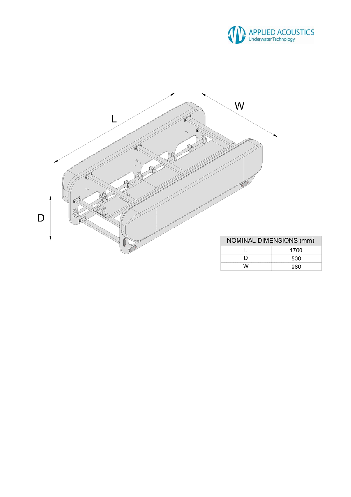
5.DIMENSIONS ........................................................................................................................................... 8
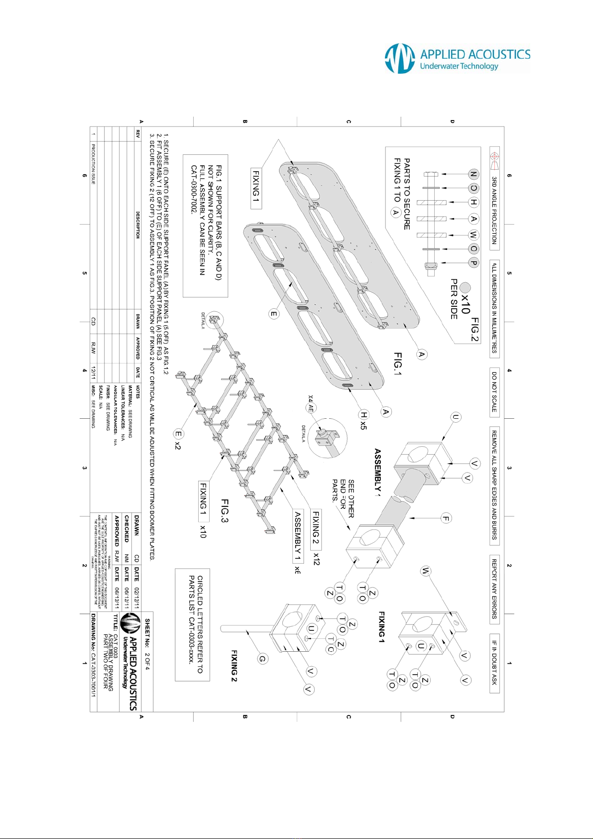
6.CATAMARAN ASSEMBLY...................................................................................................................... 9
7.CONFIGURATION.................................................................................................................................. 13
HVJ3000 JUNCTION BOX LAYOUT .................................................................................................................. 14
HVJ3000 JUNCTION BOX BUZZ BAR ARRANGEMENT ....................................................................................... 15
S-BOOM TRIPLE BOOMER ARRANGEMENT (POSITIVE CONNECTION)................................................................. 15
DOUBLE BOOMER ARRANGEMENT (POSITIVE CONNECTION)............................................................................. 15
SINGLE BOOMER ARRANGEMENT (POSITIVE CONNECTION) .............................................................................. 16
TRIPLE BOOMER ARRANGEMENT (NEGATIVE CONNECTION).............................................................................. 16
DOUBLE BOOMER ARRANGEMENT (NEGATIVE CONNECTION)............................................................................ 17
SINGLE BOOMER ARRANGEMENT (NEGATIVE CONNECTION)............................................................................. 17
8.CABLING................................................................................................................................................ 18
HVJ3000 JUNCTION BOX INTERLOCK WIRING ................................................................................................. 18
INTERLOCK CABLING SUBSEA ......................................................................................................................... 19
AA252 THERMAL INTERLOCK WIRING ............................................................................................................. 20
HVC3000 CABLE........................................................................................................................................... 21
9.DEPLOYMENT / INSTALLATION.......................................................................................................... 22
LIFTING ARRANGEMENT.................................................................................................................................. 23
10.MAINTENANCE PROCEDURES........................................................................................................ 24
11.END OF LIFE RECYCLING / DISPOSAL........................................................................................... 24
12.SPECIFICATION................................................................................................................................. 25
PHYSICAL....................................................................................................................................................... 25
SOUND OUTPUT ............................................................................................................................................. 25
COMPATIBILITY............................................................................................................................................... 25
ELECTRICAL INPUT ......................................................................................................................................... 25