POL-EKO SMART CLN 15 User manual

Laboratory incubators
models: CLN 15, CLN 32, CLN 53, CLN 115, CLN 180, CLN 240
CLW 15, CLW 32, CLW 53, CLW 115, CLW 180, CLW 240, CLW 400,
CLW 750, CLW 1000
Drying ovens
models: SLN 15, SLN 32, SLN 53, SLN 75, SLN 115, SLN 180, SLN 240
SLW 15, SLW 32, SLW 53, SLW 75, SLW 115, SLW 180, SLW 240,
SLW 400, SLW 750, SLW 1000
Drying ovens with nitrogen blow
models: SLWN1 15, SLWN1 32, SLWN1 53, SLWN1 115, SLWN1 240
SLWN2 15, SLWN2 32, SLWN2 53, SLWN2 115, SLWN2 240
Laboratory sterilizers
models: SRN 53, SRN 115, SRN 240
SRW 53, SRW 115, SRW 240, SRW 400, SRW 750, SRW 1000
Pass-through sterilizers
models: SRWP 115, SRWP 240
Before using the equipment, please read carefully this instruction manual!
Version 1.24
Issued 07.05.2021
Instruction manual SMART

Instruction manual CL, SL, SLWN, SR, SRWP SMART
2
Manufacturer's address:
POL-EKO-APARATURA sp. j.
ul. Kokoszycka 172 C
44-300 Wodzisław Śląski
Country of origin: Polska
As a manufacturer, we inform you that we took the necessary measures to ensure that this device fully meets your
expectations and is reliable for a long period of use. Due to the continuous improvement of our products, as well as the
expansion of our offer, any suggestions regarding additional functions and equipment functioning are welcome. Visit
our homepage www.pol-eko.com.pl/home-en/
Equipment disposal
This equipment is marked with the crossed out wheeled bin symbol to indicate that this equipment must not be dis-
posed of with unsorted waste. Instead it's your responsibility to correctly dispose of your equipment at lifecycle -end by
handling it over to an authorized facility for separate collection and recycling. It's also your responsibility to
decontaminate the equipment in case of biological, chemical and/or radiological contamination, so as to protect from
health hazards the persons involved in the disposal and recycling of the equipment. For more information about where
you can drop off your waste of equipment, please contact your local dealer from whom you originally purchased this
equipment.
By doing so, you will help to conserve natural and environmental resources and you will ensure that your equipment is
recycled in a manner that protects human health.
Thank you!

Instruction manual CL, SL, SLWN, SR, SRWP SMART
3
Contents
1. INTENDED USE AND IMPORTANT INFORMATION FOR THE USER.........................................................6
2. PACKAGE CONTENTS..................................................................................................................................7
3. BEFORE THE FIRST USE..............................................................................................................................8
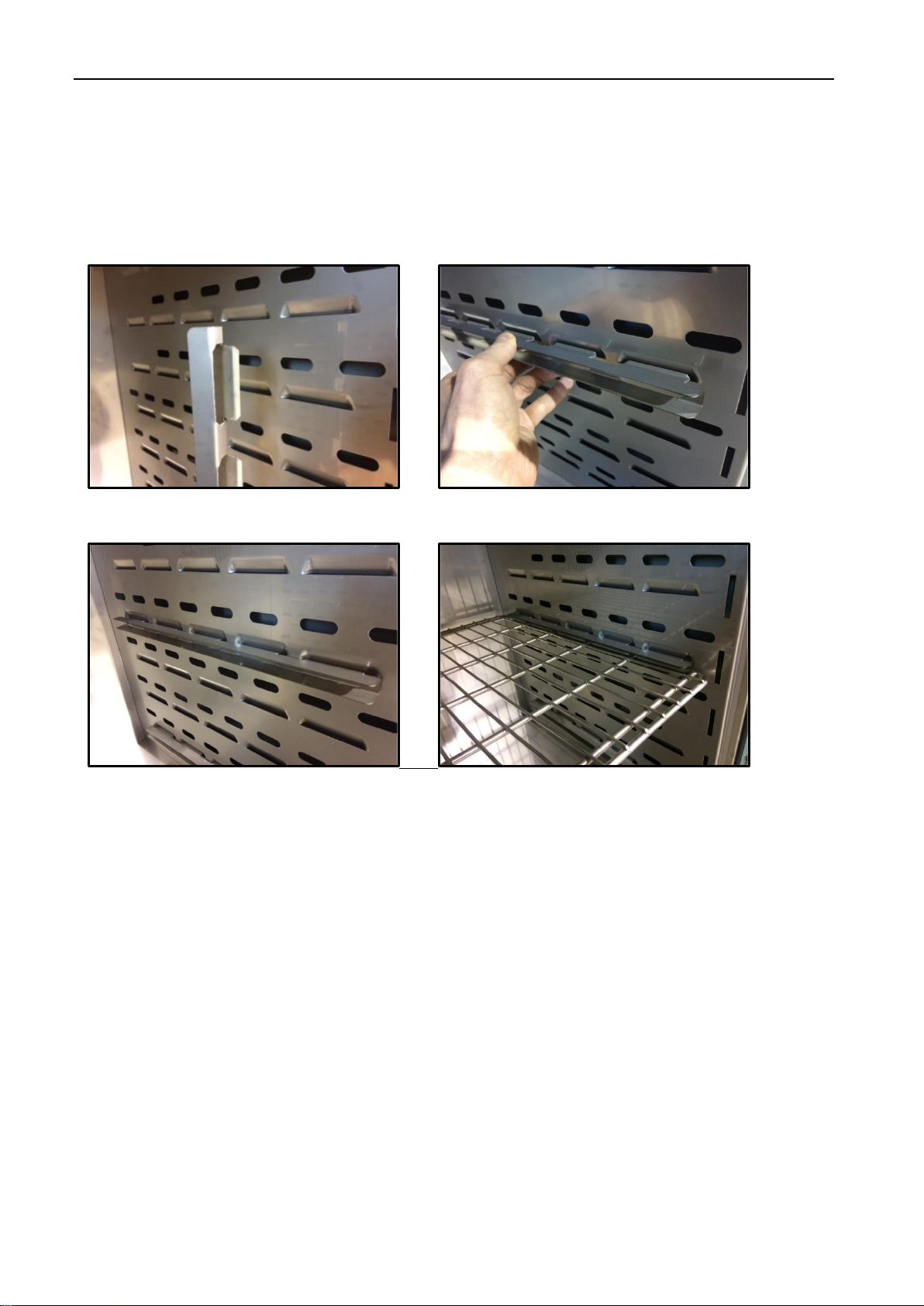
3.1. Installation of shelves ...........................................................................................................................10
3.2. Remarks on the placement of samples.................................................................................................10
3.3. Closing chamber door...........................................................................................................................11
4. DESCRIPTION OF THE DEVICE..................................................................................................................11
4.1. Design of CL, SL, SR, SRWP devices..................................................................................................11
4.2. Design of SRWP devices......................................................................................................................14
5. DEVICE EQUIPMENT (standard and optional)..........................................................................................16
5.1. External door with viewing window (optionally for CL, SL, SR).............................................................16
5.2. Internal glass door (standard for CL)....................................................................................................16
5.3. HEPA filter (optionally for all units) .......................................................................................................16
5.4. Internal socket (optionally for CL).........................................................................................................17
5.5. Door lock (standard for all units)...........................................................................................................17
5.6. Access port for external sensor (standard for all units).........................................................................18
5.7. Open door alarm (standard for all units) ...............................................................................................18
5.8. Internal light (optionally for all units) .....................................................................................................18
5.9. USB port (standard for all units)............................................................................................................19
5.10. Display battery backup (optionally for CL, SL, SLWN, SR, SRWP)......................................................19
6. DEVICE OPERATION...................................................................................................................................20
6.1. External memory (USB flash drive).......................................................................................................20
6.2. First boot...............................................................................................................................................20
6.3. Main screen.................................................................................................................................21
6.3.1. Information panel..............................................................................................................................22
6.3.2. The meaning of icons and symbols..................................................................................................24
6.3.3. Upper expandable and configurable menu.......................................................................................26
6.3.4. Alarm bar..........................................................................................................................................28
6.4. Quick Program......................................................................................................................................28
6.5. Programs.....................................................................................................................................30
6.5.1. Creating / editing a program.............................................................................................................31
6.5.2. Segments edition..............................................................................................................................32
6.5.3. Protection class................................................................................................................................35
6.5.4. Temperature protection class 3.1 (optionally)...................................................................................35
6.5.5. Priority..............................................................................................................................................35
6.5.6. Loop .................................................................................................................................................36
6.5.7. SR and SRWP devices –factory predefined sterilization programs.................................................36
6.6. Starting the program.............................................................................................................................36
6.6.1. The first way.....................................................................................................................................36
6.6.2. The second way...............................................................................................................................38

Instruction manual CL, SL, SLWN, SR, SRWP SMART
4
6.7. Quick Change of parameters................................................................................................................39
6.7.1. Quick change of set temperature .....................................................................................................39
6.7.2. Quick change of set time..................................................................................................................40
6.7.3. Quick change of fan efficiency and degree of air-flap opening.........................................................41
6.8. Statistics ......................................................................................................................................41
6.9. Data record..................................................................................................................................42
6.10. Event log .....................................................................................................................................43
6.11. Info ..............................................................................................................................................46
6.12. User settings panel......................................................................................................................46
6.12.1. Unlocking the touch screen..............................................................................................................47
6.13. Time ............................................................................................................................................48
6.14. Alarms.........................................................................................................................................49
6.14.1. Mute option.......................................................................................................................................49
6.15. Network.......................................................................................................................................50
6.16. Corrections...................................................................................................................................51
6.17. Archives.....................................................................................................................................52
7. INTERFACE..................................................................................................................................................52
7.1. MODBUS TCP......................................................................................................................................52
8. TEMPERATURE PROTECTION...................................................................................................................53
8.1. Temperature protection class in CL, SL, SR, SRWP models ...............................................................53
9. SLWN DRYING OVENS WITH NITROGEN BLOW......................................................................................54
9.1. Description of the kit.............................................................................................................................54
9.2. Connection............................................................................................................................................56
9.2.1. Connection of the Kit A.....................................................................................................................56
9.2.2. Connection of the Kit B.....................................................................................................................57
9.2.3. Connection of the Kit C.....................................................................................................................58
9.3. Shut-off solenoid valve for gas supply (optionally)................................................................................59
9.4. Operation and maintenance of the dry nitrogen blow system...............................................................59
9.5. Methodology for calculating the nitrogen flow rate in the drying oven...................................................60
10. SRWP pass-through sterilizers..................................................................................................................62
10.1. Precautions...........................................................................................................................................62
10.2. Package contents.................................................................................................................................62
10.3. Preparing the aperture in the wall.........................................................................................................62
10.4. Installation of SRWP sterilizer...............................................................................................................63
11. CONNECTING THE DEVICE TO A COMPUTER.........................................................................................65
12. CLEANING AND MAINTENANCE OF THE DEVICE...................................................................................65

Instruction manual CL, SL, SLWN, SR, SRWP SMART
5
12.1. Exterior cleaning...................................................................................................................................66
12.2. Interior cleaning....................................................................................................................................66
12.3. Cleaning the touch screen....................................................................................................................67
12.4. Consumables........................................................................................................................................68
13. ADVICE ON HOW TO SAFELY STORE THE DEVICE................................................................................68
14. TROUBLESHOOTING..................................................................................................................................68
14.1. Possible defects....................................................................................................................................68
15. WARRANTY CONDITIONS..........................................................................................................................69
16. RATING PLATE............................................................................................................................................70
17. TECHNICAL DATA.......................................................................................................................................71
17.1. CL, SL, SLWN*, SR, SRWP** devices .................................................................................................71
18. DECLARATIONs OF CONFORMITY ...........................................................................................................73

Instruction manual CL, SL, SLWN, SR, SRWP SMART
6
1. INTENDED USE AND IMPORTANT INFORMATION FOR THE USER
CL laboratory incubators, SL drying ovens, SR laboratory sterilizers are laboratory devices designed for incubation,
drying and sterilization with hot air of samples at following temperature ranges:
•laboratory incubators CL: 5C above ambient temperature … +100C
•drying ovens SL: 5C above ambient temperature … +300C
•laboratory sterilizers SR: 5C above ambient temperature … +250C
•pass-through laboratory sterilizers SRWP: 5C above ambient temperature … +250C
•drying ovens with nitrogen or other inert gas blow: 5C above ambient temperature … +250C
Laboratory incubators, drying ovens and laboratory sterilizers have an electric heating system. All devices are
controlled by a precise SMART controller, thanks to which the set temperature is maintained with good fluctuation and
variation. The devices are available in the following versions:
•with natural (N) air convection: models CLN, SLN, SRN
•forced (W) air convection: models CLW, SLW, SLWN, SRW (in the chamber there is one or more fans,
depending on unit’s capacity, which force air movement –for devices with forced air circulation, the symbol
appears on the screen.
Drying ovens with nitrogen flow, SLWN1 and SLWN2 models are used, among others, for the determination of total
moisture in hard coal according to the PN-ISO 589:2006 norm which requires that coal samples susceptible to oxida-
tion should be dried at a temperature of + 105°C in a drying oven with a nitrogen flow.
Requirements for the use of the equipment are given in point 6 of the norm. A drying oven with nitrogen flow should be
used to control the temperature in the range of + 105°C to + 110°C with the additional possibility of blowing with a
stream of dry nitrogen at a flow rate of about 15 volumes of the drying oven per hour. For detailed information on the
available models and equipment, see Section 9.
The meaning of information symbols
This symbol means that failure to follow the instructions could endanger people's health or life, or
damage the device. The manufacturer is not liable for damages resulting from non-compliance with
the instructions contained in the manual.
Applies to SL and SR: when operating at high temperatures (over 200°C), the door and the unit
housing may be hot.
This symbol indicates helpful tips.
To guarantee your security and the longevity of the unit, please comply with the following rules:
1.
The unit cannot be installed:
•outside,
•in damp places or places which can be easily flooded,
•near flammable or volatile substances,
•near acids or in corrosive environments.
2.
It is forbidden to:
•store inflammable or volatile substances inside the unit –equipment is not made in an explosion-proof
version,
•touch live parts of the unit,
•operate the unit with wet hands,
•put water vessels on the unit,
•climb on the unit,

Instruction manual CL, SL, SLWN, SR, SRWP SMART
7
•overload the shelves (the maximum load is described in technical data).
3.
You should:
•place samples in such a way to provide proper air circulation in the chamber,
•open the door for the shortest period of time to reduce temperature fluctuations,
•secure samples from being blown out by the chamber fan e.g powdery samples,
•always check that the doors are closed correctly,
•use only mains with earth to avoid electric shocks,
•unplug the power cable holding the protective cover and not the cable itself,
•disconnect the unit from the mains before undertaking any repairs or maintenance work (in order to not
lose the warranty during its duration, all repairs should be carried out by an authorized service),
•protect the power cable and the plug from any damage,
•disconnect the power plug before moving the unit,
•disconnect the power plug if the device will not be used for a long period of time,
•disconnect the unit and protect it from reconnecting if it has any visual fault.
Failure to comply with the above recommendations may result in damage to the device or deterioration of
technical parameters, as well as loss of warranty.
2. PACKAGE CONTENTS
Drying ovens (SL) and laboratory incubators (CL) in SMART version are delivered with:
Device
SL/CL
Capacity
15
32
53
75
115
180
240
400
750
1000
Shelves [pcs.]
1
1
2
2
2
3
3
3
5
6
Slides [pcs.]
2
2
4
4
4
6
6
6
10
12
Power cord [pcs.]
1
1
1
1
1
1
1
1
1
1
SL - INTEGRATED
Rubber cap [pcs.]
x
x
1
1
1
1
1
1
1
1
Key for door lock [pcs.]
2
2
2
2
2
2
2
2
2
2
Wrench (13mm) for wheels adjustment
[pcs.]
x
x
x
x
x
x
x
1
1
1
Quality Control Certificate [pcs.]
1
1
1
1
1
1
1
1
1
1
Laboratory sterilizers (SR) in SMART version are delivered with:
Device
SR
Capacity
53
115
240
400
750
1000
Shelves [pcs.]
2
2
3
3
5
6
Slides [pcs.]
4
4
6
6
10
12
Power cord [pcs.]
1
1
1
1
1
1
Rubber cap [pcs.]
1
1
1
1
1
1
Key for door lock [pcs.]
2
2
2
2
2
2
Wrench (13mm) for wheels adjustment [pcs.]
x
x
x
1
1
1
Quality Control Certificate [pcs.]
1
1
1
1
1
1
The manufacturer is not responsible for corrosion, damage to electronics or other elements of the
equipment caused by placing inside substances that have an adverse effect on the materials from
which it was made.

Instruction manual CL, SL, SLWN, SR, SRWP SMART
8
Pass-through sterilizers (SRWP) in SMART version are delivered with:
Device
SRWP
Capacity
115
240
Shelves [pcs.]
2
3
Slides [pcs.]
4
6
Power cord [pcs.]
1
1
Rubber cap [pcs.]
1
1
Key for door lock [pcs.]
4
4
Stand
1
1
Masking element
2
2
Quality Control Certificate [pcs.]
1
1
3. BEFORE THE FIRST USE
The manufacturer sends the device protected by cardboard profiles and foil. The device should be transported in an
upright position and the package should be secured against sliding during transport.
After transporting the device at a temperature below 10°С, wait at least 2 hours before connecting it
to the mains.
On the surface of unit’s components made of stainless steel, slight discoloration may occur. It is a result of the
technologies used in the production of metal sheet in accordance with the requirements of PN-EN 10088-2 standard
and it is not a defect of the unit.
In SL drying ovens, SR sterilizers and CL laboratory incubators there’s a ventilation air-flap at the
back of the device. Hot air comes out of the air-flap during operation of the device. The
manufacturer recommends using a non-flammable insulation screen on the wall or increasing the
distance from the wall. Failure to do so may result in permanent damage to the wall, and in extreme
cases even a fire.
Applies to drying ovens (SL, SLWN) and sterilizers (SR, SRWP). Before first boot, it is recommended
to turn on the device for 3 hours at the set temperature of 250°C. There might be a specific smell
coming out from the interior of the chamber and this is not a malfunction.
The place of installation of the unit should meet the following conditions:
•ambient temperature +10°C...+28°C,
•recommended relative humidity of the ambient air up to 60%,
•the unit has not been designed to work in highly dusty environments,
•ensure proper ventilation in the room,
•the device should be placed on a hard and stable surface,
•the unit should be placed at least 100mm away from the walls,
•the height of the room must be at least 300mm greater than the height of the unit,
•the unit is not designed to be built-in,
•the place of installation of the device should be equipped with a socket with parameters suitable for the
device.
After receiving the device, visually assess its condition and equipment in the presence of the
person delivering the goods. A courier company is responsible for any damage caused during
transport.

Instruction manual CL, SL, SLWN, SR, SRWP SMART
9
If you don’t comply with the above recommendations, the unit may get broken or it may worsen the technical
parameters such as:
•temperature fluctuation,
•temperature variation,
•power consumption
and may result in loss of warranty.
Wheels / leveling feet
If the device has been equipped with wheels or leveling feet:
•in the case of wheels after placing the unit at its destination, secure the device against
movement by locking the wheels
•in the case of feet, after placing the device in the destination, they should be leveled.
If the device is equipped with wheels, they must be locked and leveled. For this purpose
use the red knob mounted in the wheel housing. At the beginning, the knob can be
turned by hand, if it encounters resistance, use a 13 size wrench.
If the device is to be placed on a table (option) or base (option) which is equipped with the wheels with a lock, the
wheels MUST be locked after placing the table / base in its final destination.
Electric installation
Power supply of the equipment is indicated on a rating plate on the unit. Connect the device to a
socket with ground in order to avoid electric shocks in case of the unit’s failure.
The installation should be protected by a 16A slow-blow fuse and equipped with a residual current device.
Leveling wheels are ONLY for positioning the device at its destination. They can not be used to
transport the device!

Instruction manual CL, SL, SLWN, SR, SRWP SMART
10
3.1. Installation of shelves
To install the shelf or to change its position, follow these steps:
Install the shelf slide at the selected height by inserting it into perforations on the wall of the device. Do the same with
the slide on the opposite wall.
Slide the shelf into the installed shelf slides. Now, the shelf is correctly installed!
To remove a shelf, perform the above steps in reverse order.
3.2. Remarks on the placement of samples
To provide proper air circulation and stable conditions in which the samples are stored in the chamber, it is necessary
to keep the following rules:
•the max height of the samples should not exceed 1/3 of the space between the shelves,
•approx. 1/3 of the width and depth of the shelf should remain empty, while the distances between the
samples, as well as between the samples and the wall should be approximately equal.
The picture below is an example of the placement of samples in the chamber.

Instruction manual CL, SL, SLWN, SR, SRWP SMART
11
Hmax
H
Hmax
a
uv w
xy z
b
u+v+w > 1/3 a
x+y+z > 1/3 b
Hmax = 2/3H
u v w
x y z
H
≅
≅ ≅
≅
Front view
Top view
Shelf
Following the above rules will provide best optimal parameters of temperature fluctuation and variation.
3.3. Closing chamber door
The external solid door of the units CL, SL and SR have two-point lock and open door sensor. If the door has not been
closed properly, audible alarm will sound. You can set delay door alarm by: 30s, 1 min, 2 min, 5 min or 10 min (see
Section 6.14).
4. DESCRIPTION OF THE DEVICE
SMART models are equipped with a PID microprocessor temperature controller and a 4.3 inch color touch screen with
a resolution of 800x480.
4.1. Design of CL, SL, SR, SRWP devices
Below there’s a picture showing CL, SL, SR, SRWP type devices (exemplary picture) with a description of the
important components of the device.
The elements of the device are shown on the basis of a CLN 53.

Instruction manual CL, SL, SLWN, SR, SRWP SMART
12
Front view
1) rating plate
2) access port ø30mm for external
sensor
3) internal glass door (for CL)
4) adjustable feet
5) shelf
6) external solid door
7) temperature sensors
8) open door sensor
9) touch control panel
10) USB port
11) handle with key lock
1
2
3
7
4
5
6
10
9
8
11

Instruction manual CL, SL, SLWN, SR, SRWP SMART
13
6
5
4
3
1
2
Rear view
1) main switch
2) connector for connecting a hose
with nitrogen (only for SLWN
models)
3) air-flap
4) LAN port
5) fuse
6) main power socket C20

Instruction manual CL, SL, SLWN, SR, SRWP SMART
14
4.2. Design of SRWP devices
Below there’s a picture of pass-through sterilizer (exemplary photo) with a description of the important components of
the device.
Front view
1) main power socket C20
2) rating plate
3) access port ø30mm for external sensor
4) external solid door with handle with a key lock
5) touch control panel
6) USB port
7) ventilation grille
8) open door sensor
9) fuse
10) electronics cooling fan
11) LAN port
Side view
1) main switch
1
2
3
11
10
9
7
5
8
6
4

Instruction manual CL, SL, SLWN, SR, SRWP SMART
15
Rear view
1) green diode –lights up when the device is turned on
2) yellow diode - pulsates when the set temperature is being reached; lights up when the set temperature is reached
3) red diode - it lights up in the event of an alarm
4) external solid door
5) handle with a key lock
1
2
3
4
5
5
4

Instruction manual CL, SL, SLWN, SR, SRWP SMART
16
5. DEVICE EQUIPMENT (STANDARD AND OPTIONAL)
5.1. External door with viewing window (optionally for CL, SL, SR)
The external door with a viewing window is an optional equipment for CL, SL, SR models (except for CL/SL 15,32).
In SL drying ovens with door with viewing window, the maximum operating temperature is lowered to
+250°C at the factory.
During operation, when the temperature inside the chamber is high, do not touch components of
the external door with viewing window, as there is a risk of burns. Use protective gloves to
protect yourself against the effects of burns from hot components.
5.2. Internal glass door (standard for CL)
Internal glass door is a standard equipment in CL laboratory incubators. To open and
close the door use the plastic handle attached to the glass.
During operation, when the temperature inside the chamber is high, do not touch the internal
components and glass door, as there is a risk of burns. Use protective gloves to protect yourself
against the effects of burns from hot components.
5.3. HEPA filter (optionally for all units)
The HEPA filter is an optional accessory for CL incubators, SL drying ovens and
sterilizers. HEPA filter is used where the highest standards of clean air are required.
The equipment at the production stage is adapted to the installation of the filter. The
filter has H13 class to PN-EN1822-1:2019 norm. It’s located at the rear of the unit. The
filter itself is delivered separately. You should place it in the square filter cover so the
black gasket is outside, then screw the cover to the rear wall of the unit. Please ensure
that the distance between the filter and wall is not less than 100mm.
We do not recommend installing and removing internal glass door. Incorrect assembly or disassembly
may result in damage to the glass and injury to the user.

Instruction manual CL, SL, SLWN, SR, SRWP SMART
17
5.4. Internal socket (optionally for CL)
An internal socket with grounding and IP44 protection is an optional equipment for CL laboratory incubators. The
internal socket (depending on the model: 230V 50Hz / 230V 60Hz / 115V 60Hz) is intended for EU plugs or plugs type
B. The socket can be used to connect electrical devices inside the device.
In laboratory incubators with internal socket the maximum operating temperature is lowered to +70°C at
the factory.
Always make sure that the safety rules for working with electrical devices are followed!
5.5. Door lock (standard for all units)
All devices have a key lock. In the models CL, SL, SR, SRWP the key lock is situated in the door handle. Two keys are
supplied with the device (hung on the back of the device). Together with SRWP model 4 keys are provided.
The maximum permissible load of all sockets inside the device (max. 3 pcs.) is 200 [W].

Instruction manual CL, SL, SLWN, SR, SRWP SMART
18
5.6. Access port for external sensor (standard for all units)
A Ø30 mm access port can be used to insert an external temperature sensor for independent temperature control
inside the device. The access port has been secured with a rubber plug. The plug should cover the access port while
the unit is operating. If multiple cables have been inserted through the access port and it is not possible to use the plug,
secure the access port with adhesive tape. If you leave the access port open, it may affect temperature fluctuation and
variation inside the chamber.
5.7. Open door alarm (standard for all units)
All units have been equipped with an open door sensor. If you open the door, the icon: will appear (the number
above the icon presents open door counter. Press the icon to cancel the counter. The counter is also cancelled by
turning of the device). If the door remains open longer than the time set by the user (30s, 1 min, 2 min, 5 min, 10 min)
an acoustic signal, red pulsating alarm bar and „open door” alarm with active status will appear.
In SRWP pass-through sterilizers, the open door sensor is located on the front and back of the device - the open door
alarm is activated for the front and rear door.
5.8. Internal light (optionally for all units)
Internal light is optional for CL, SL, SR and SRWP devices. Internal light is integrated with an open door sensor. When
the light switches on, the icon . will appear on the display. For devices with door with viewing window, pressing
the icon allows you to turn the light ON or OFF (the light is not integrated with the open door sensor).
In incubators with internal light, the maximum operating temperature is lowered to + 70°C at the factory.
In drying ovens with internal light, the maximum operating temperature is factory reduced to + 250°C.
Open door sensor

Instruction manual CL, SL, SLWN, SR, SRWP SMART
19
5.9. USB port (standard for all units)
The USB port on the front panel is used only to transfer data from the device's internal memory to the flash drive. To do
this, insert the flash drive into the USB port on the front panel and then:
•go to the main menu ,
•go to the data record ,
•press and choose type of the file: *.csv, or *.plkx.
•press . Data has been copied.
After copying the data to the USB flash drive, before removing it from the USB socket, it should be unmoun-
ted by pressing the icon in the top drop-down list (Figure 1). If the pendrive is not unmounted after
connecting to the computer, a message about pendrive damage may be displayed with a repair proposal,
when actually the pendrive is not damaged
Figure 1 Unmounting USB flash drive
Data saved in the * .csv file can be opened in a spreadsheet. Data saved as * .plkx can be opened in the Lab Desk
program (additionally paid option). This program allows, among others, for data preview in the form of a table or a
graph. It also allows you to prepare a statistic report for a selected range of data, more information Section 6.9.
5.10.Display battery backup (optionally for CL, SL, SLWN, SR, SRWP)
Units in the SMART version can be optionally equipped with a battery backup of the display. The power loss and
switching to the battery backup display mode is signaled by a pulsating red frame around the display and a sound
signal (if it is turned on). In the battery backup display mode, all parameters are displayed, ie temperature. Other
alarms, e.g. exceeding the temperature range, are also signaled.
In order to extend the battery life, the display is dimmed all the time. Batteries are automatically charged in AC mode.

Instruction manual CL, SL, SLWN, SR, SRWP SMART
20
Batteries should be replaced every 12 months. During the warranty period, the replacement should be
performed by an authorized service. Otherwise, you will lose your warranty.
6. DEVICE OPERATION
This symbol means that a given window can be moved in the direction shown in the
picture.
6.1. External memory (USB flash drive)
The external memory (USB flash drive) allows to copy: instruction manual, data record, event log and service log from
the device memory. Before first use, the USB flash drive should be formatted in the FAT 32 file system. Insert the
device in the USB slot on the front of the device next to the display. Wait a few seconds, the correct reading is
indicated by the message „USB flashdrive connected” at the bottom of the screen.
6.2. First boot
During the first boot, the screen (Figure 2) will display information about saving the "Download" folder (with instruction
manual in pdf format) on the USB flash drive. In order to do it, insert the USB flash drive and wait a second for
hardware detection, then press .
If you press you quit downloading the folder. The window will appear again during the next boot. You can tick
„Don’t show again” so that the window will not be displayed after switching on the device. You can always download
the "Download" folder in the Info submenu. More information Section 6.11.
After copying the data to the USB flash drive, before removing it from the USB socket, it should be unmoun-
ted (see Section 5.8.).
USB slot is used to connect only a flash memory –a pendrive or a card reader with a memory card.
Connecting any other device (e.g. external hard drive) without consultation is not authorized by the
manufacturer and may damage the USB slot.
This manual suits for next models
52
Table of contents
Other POL-EKO Laboratory Equipment manuals