uv guard T Series User manual

Installation
and Operation
Manual
ATTENTION: Please read this manual carefully and follow the instructions.
Installation shall be carried out only by authorised technicians.
1300 052 052
uvguard.com
© Copyright UV Guard Australia. All rights reserved.
T-Series™
Models: UVG T10, UVG T18, UVG T30,
UVG T40 & UVG T75
T18 with
2” Tri-Clover
T10 with
1 ½” BSPT T30 with
3/4” Table D
T40/T75 with
2” Table D

2
T-Series™

3
T-Series™
Contents
1. Introduction ............................................................................................................ 4
1.1 General Safety Instructions 4
2. Assembly And Installation ..................................................................................... 5
2.1 Installing the Reactor 8
2.2 View Port or UV Intensity Sensor Installation 9
2.3 Quartz Thimble and UV Lamp Installation 10
2.4 Power Supply Box 13
2.5 Basic Thermal Relief Valve Installation 14
2.6 Industrial Thermal Relief System Installation 14
2.7 Building Management System (BMS) Fault Connection 15
2.8 SMS Alarm Module 16
3. Servicing And Operating ........................................................................................ 18
3.1 Servicing the Quartz Thimble 18
3.2 Servicing the UV lamp 19
3.3 Servicing the UV Sensor 20
3.4 Servicing and Operating the 40050 and 40090 Power Supply Boxes 20
3.5 Servicing and Operating the PLC Power Supply Boxes 22
4. Spare Parts ............................................................................................................ 24
5. Warranty Information ............................................................................................ 25

4
T-Series™
1. Getting Started
Delivery Inspection
Each unit is tested prior to packaging to ensure that the unit is operational and in good working
order.
Upon receipt of goods, be sure to check the shipment for any signs of damage, and if any
damage has occurred, notify both the carrier and the shipper in writing within 72 hours of the
damage and retain the parts and packaging for inspection.
Check that all working parts of the unit have been received.
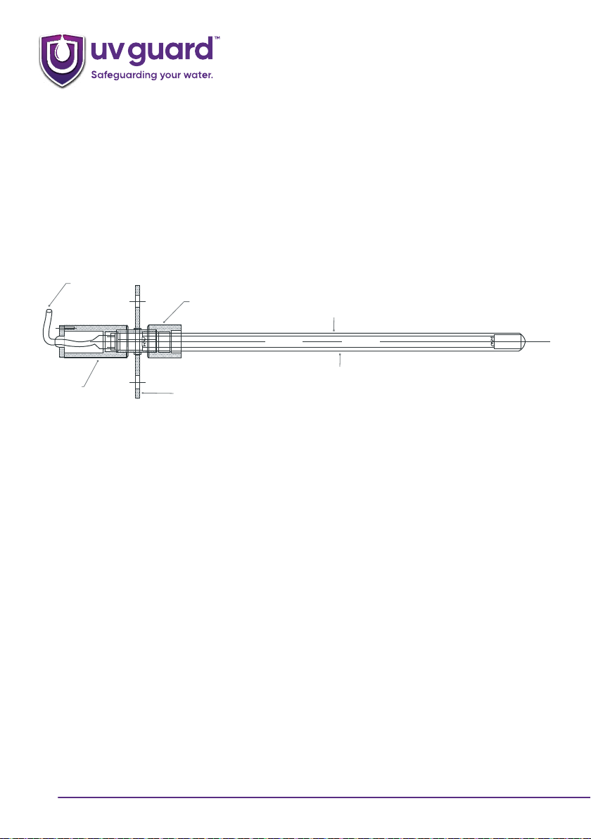
For a UVG T Series unit this will include:-
a. Tank Connection with Sealing Nuts
b. Power Supply Box with 4 Pin lamp connector
c. Quartz Thimble
d. UV lamp
e. O ring x 2 (normally included in tank connection)
Spares:-
Item UVG T20 UVG T30 UVG T30
UV lamp (ozone free) 11020 11030 11040
UV lamp (ozone producing) -11031 11041
Quartz thimble 20280 20290 20310
O ring seal 31000 31000 31000
2. SETTING UP
Disinfection Unit Mounting
The UVG T Series disinfection unit comes complete with its own flange mount. The standard flange will
be 2” table D. Other options such as, BSM, BSP, Triclover, Table E flange etc… are available on request.
The unit can be mounted in the vertical or horizontal position
Up to one metre space is required on the outside of the tank at the power head for servicing purposes.
(T40 requires 1000mm, T30 requires 600mm, T20 requires 400mm)
Ensure there is sucient space inside the tank to accommodate the glassware without interfering with
any mechanical components such as mixers.

5
T-Series™
Ensure the UV lamp and quartz thimble will not be impacted by any inlet flows or mechanical stress
that may cause them to break.
The components of the T series units that are inside the tank are water proof and can be fully
immersed.
Quartz Thimble
UV Lamp
Internal Clearance
Required Space Required For Servicing
BA
Internal Sealing Nut External Sealing Nut
Flange Tank Connection
Model \ Dimension A B
UVG T20 190 mm 300 mm
UVG T30 460 mm 600 mm
UVG T40 850 mm 1000 mm

6
T-Series™
3. ASSEMBLY
DUE TO THE FRAGILE NATURE OF THE QUARTZ THIMBLE - CARE MUST BE TAKEN WHEN INSTALLING THE
QUARTZ SLEEVE AND UV LAMP
Quartz Thimble Installation
Step 1
Unscrew the external sealing nut and the internal sealing nut from the end of the stainless steel tank
connection unit. Ensure that O ring 1 is sitting inside the threaded end of the external sealing nut (it
must sit inside its designated O ring groove immediately following the thread). Once this has been
checked, smear the O ring with some silicon grease.
Step 2
Unscrew the internal sealing nut from the stainless steel body and insert O ring 2 into the internal
sealing nut and lubricate the O ring with silicon grease.
Step 3
Remove the quartz thimble from its protective wrapping and insert the open end into the external
sealing nut so it slips past the O ring and rests against the stop inside the sealing nut and will not go
any further.
Step 4
Carefully hold the external sealing nut and quartz thimble and insert the domed end of the quartz
thimble through the nipple on the external side of the tank connection flange. Insert it all the way until
the sealing nut meets the sealing nipple and screw the sealing nut firmly hand tight.
Step 5
Now take the internal sealing nut with the O ring in place and insert the domed end of the quartz
thimble through the threaded opening of the internal sealing nut. Push the thimble up through the O
ring (or slide the internal sealing nut and O ring down the quartz thimble) until the threads meet and
then screw the internal sealing nut hand tight. There are now two O ring seals on the quartz thimble.
During this process silicon grease will be smeared on the outside of the quartz thimble.

7
T-Series™
Step 6
Having checked that the thimble is securely in its support, clean the quartz with methylated spirits on
a tissue to remove the silicon grease smear and fingerprints and dry with a clean cloth or tissue. With
step 6 complete the thimble is now in place.
Step 7
Now insert the complete assembly through the hole in the tank with the matching flange / connector
on the tank and secure the unit to the tank. Take care not to bang the quartz against the opening
when inserting it and securing the fitting. UV Lamp Installation
UV Lamp Installation
COTTON GLOVES OR SIMILAR SHOULD BE WORN WHEN HANDLING THE UV LAMP - FINGER PRINTS OR
MARKS OF ANY NATURE WILL HAVE A DETRIMENTAL EFFECT ON THE UV TUBES PERFORMANCE.
Step 1
Check that the quartz thimble is in place and the thimble O ring is compressed onto the thimble itself.
Step 2
Remove the UV lamp from its protective wrapping and wipe down with alcohol or methylated spirits
using a soft cloth or tissue.
Step 3
Insert the UV lamp into the quartz thimble through the sealing nut gasket and through the centre of
the sealing nut. Keep a firm hold of the UV lamp at all times until the lamp is properly connected to the
lamp lead. If the unit is installed vertically, NEVER drop the lamp into the quartz thimble, as this may
break the quartz thimble. Do not drop the UV lamp into the quartz thimble.
Step 4
Always keep a firm hold of the UV lamp until it is secured to its four pin connector. Push the female
4 pin connector firmly on to the lamp pins. Slide the UV lamp gently up into the thimble, holding the
lamp lead, until it will go no further.

8
T-Series™
Step 5
Locate the three holes in the end cap with the three holes on the end of the sealing nut. Screw all
three screws (M3) through the holes in the end cap, into the sealing nut.
Turn power on and the UV lamp will ignite. However it will take between 2 and 5 minutes for the lamp
to reach full output.
Quartz Tube
SS Sealing Nut
Power Cable
2” Table D Flange
(Other options also available: 2”
BSM, BSPM or Triclover)
UV Lamp
Aluminium
Sealing Nut
4. SERVICING
The following service schedule should be followed:-
Quartz thimble:
•Thimble is to be cleaned every 6 months or as required.
•Thimble is to be replaced every 24 months.
UV lamp:
•The lamp is to be replaced every 12 months.
Materials required for servicing:
•Cleansing cream or similar
•Methylated spirits or alcohol solution
•Soft tissue/cloth
•Silicon grease
•Cotton gloves

9
T-Series™
Servicing the UV Lamp
Step 1
Switch the mains power to the UV disinfection unit o.
Step 2
Remove the three screws that hold the end cap in place on the end of the sealing nut. The UV lamp
will be attached to the lead that goes through the end cap.
Step 3
Carefully pull the UV lamp out through the external sealing nut with the lamp lead. When there is
enough clearance and you can hold the UV lamp, disconnect the lamp connector from the UV lamp
and then remove the lamp completely from inside the quartz thimble. Always keep hold of the UV
lamp to prevent it being dropped into tank fitting and breaking the quartz thimble.
Step 4
Remove the replacement UV lamp from it’s protective wrapping and wipe down with a soft tissue/
cloth soaked in methylated spirits to remove any fingerprints.
Step 5
Insert the UV lamp into the quartz thimble through sealing nut gasket and the centre of the sealing
nut. If the unit is installed vertically, NEVER drop the lamp into the quartz thimble, as this may break the
quartz thimble. Do not drop the UV lamp into the quartz thimble.
Step 6
Always keep a firm hold of the UV lamp until it is secured to its four pin connector. Push the female
4 pin connector firmly on to the lamp pins. Slide the UV lamp gently up into the thimble, holding the
lamp lead, until it will go no further.
Step 7
Locate the three holes in the end cap with the three holes on the end of the sealing nut. Screw all
three screws (M3) through the holes in the end cap, into the sealing nut.
Switch power on - the UV lamp should flicker and come on. 2-5 minutes should pass before the UV
lamp has reached maximum output.

10
T-Series™
Servicing the Quartz Thimble:
Step 1
Switch o main power supply to the UV disinfection unit.
Step 2
Remove the UV lamp (refer to servicing of the UV lamp)
Step 3
•Note cotton gloves should be worn when handling the quartz thimble
Ensure that the liquid level in the tank is below the level of the connecting flange. Carefully disconnect
the flange / connection fitting from the tank, and carefully remove the unit with thimble attached
without banging the quartz against the tank opening. Particular care needs to be taken when the
quartz is installed horizontally, so the fitting doesn’t drop when it is fully disconnected from the tank.
Great care needs to be taken to avoid damaging the quartz thimble during this process. If the quartz
is broken inside the tank then the tank will need to be drained and cleaned to remove any of the
broken quartz.
i) If the thimble and O rings do not need replacing, then simply wipe down the thimble with a non-
abrasive cleansing cream and then wash down with water, taking care not to get water inside
the thimble. When the thimble is clean, wipe it down with methylated spirits. Then replace the
unit as described in the installation procedures.
ii) If the thimble or O rings need replacing then remove the thimble from its holding flange by
first unscrewing and removing the internal sealing nut and then unscrewing and removing the
external sealing nut. A new thimble and new O rings can be fitted as previously described in the
installation procedures .
Having completed this step the lamp needs to be reinstalled (see ‘Servicing of the UV lamp’), and the
unit will be ready for use.

11
T-Series™

UV-Guard Australia Pty Ltd
Head oce - 18/7 Packard Avenue
Castle Hill, NSW, 2154
sales@uvguard.com
+61 2 9631 4900
uvguard.com
This manual suits for next models
5
Table of contents