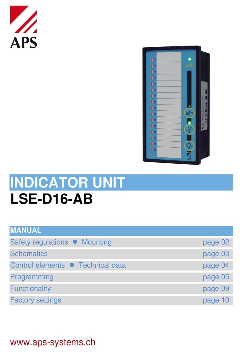
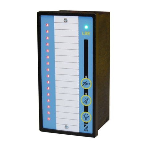
APS LSE-D16-BS User manual

OPERATION-/FAULT INDICATOR
LSE-D16-BS
MANUAL
Safety regulations Mounting page 02
Schematics page 03
Control elements Technical data page 04
Programming page 05
Functionality page 07
Factory settings page 10
www.aps-systems.ch

2
Safety regulations
Before the installation of the LSE-D16 Operation-/Fault indicator read these
instructions carefully and completely. Improper handling can result in severe
personal injury, substantial property damage or even death.
Cleaning
Before cleaning first disconnect the equipment from the mains. Do not use any
liquid cleaner or corrosive agent but solely a dampened cloth.
Installation
Installation work must be carried out by certified technical staff only. Follow the
instructions in this handbook. Observe the locally applicable regulations for the
safe and riskless handling of electrical installations
Supplementary power
Power supplies for the LSE-D16 Operation-/Fault indicator must comply with
the stipulations for safety extra-low voltage (SELV) given in IEC 346-4-41. We
recommend our power supplies of the EcoPower Series as they fulfil these
stipulations completely
Switching on the system
The LSE-D16 Operation-/Fault indicator has no master switch: the system is
alive as soon as the power supply has been switched on.
A switch must be provided in the building installation as a cut-off device. The
switch must be labelled appropriately, must be in the vicinity of the equipment
and must be easily accessible to the user.
Mounting
Firstly, the front cut-out of 138 x 68 mm must be made. Then slide the LSE-
D16 Operation-/Fault indicator trough the cut-out and fix the mounting clips.
Finally, tighten the screws of the mounting clips.
All electrical connections are effected by the plug-in screw terminals

3
Schematics
*
The functions of the outputs LT (Lamp test), LQ (Lamp acknowledgement) and
HQ (Horn acknowledgement.) can be customised see page 9, output
functions.
The LAN connection is currently used only for firmware updates only.

4
Control elements
The following buttons are integrated in the front of the unit:
Horn acknowl.
The built-in buzzer and the horn output are
deactivated.
Lamp acknowl
All queued alarms are acknowledged
Lamp acknowl.
All LEDs as well as the lamp test output are
activated for appr. 5 seconds.
Technical data
Indicator process
New value or first-up indicator
Signalling
16 Multicolour LED / integrated buzzer
Indicator inputs
16 inputs each, NO/NC operation/fault
Time delay
5s/10s/60s for all fault inputs, global
Automatic alarm acknowledgement
5s/10s/60s for all fault inputs, global
NO/NC
All operation –fault inputs, separate
System inputs
Horn ack. HQ / lamp ack. HQ / lamp test LT
System outputs
Horn until HQ / common. / lamp test 5sec.
Optional output functions
HQ button / LQ button / common priority 2
Maximum load output relais
6A 30VDC 7 6A 250VAC
Control elements
Horn ack. / alarm ack. / lamp test
Supply voltage
8-30VDC / 12-28.5VAC, 40-80Hz
Signal voltage
24V AC/DC ± 20%
Voltage system inputs
Analogue Supply voltage
Voltage system outputs
Current sink max. 30VDC
System output load
Max. 50mA
Power consumption
Max. 3W
Weight
260g
Dimensions WxHxD
72x144x75mm
Front panel cut out
138 x 68mm
Terminals
Plug-in screw terminals 0.2 -. 2.5mm2
Mounting position
Any
Protection degree housing
IP40
Protection connector
IP20
Temperature range
0 to 65°C

5
Programming
General
Programming can be done either with the web interface or with the operating
elements on the unit. The use of the web interface is described in a separate
documentation. Download the documentation from the homepage: www.aps-
systems.ch
Using the controls in programming mode:
Icon
Description
Designation
Function in programming mode
Horn
acknowledgement
HQ
Navigation up
Alarm acknowledge
LQ
Switch
Lamp test
LT
Navigation down
The programming mode is started as follows:
Power up the unit and push the HQ and LT keys at the same time within 10
seconds. If no other keys are pressed within 5 seconds, LSE-D16 will switch
back to operating mode. If additional keys are pressed, the programming mode
remains active for 30 seconds. If no other key is pressed for 30 seconds, LSE-
D16 will return to operating mode and will take over the programming. The
programming mode can be ended by pushing the HQ and LT keys. The
settings are saved. While the programming mode is active, the power LED
blinks green.
Programming levels
LSE-D16-BS Operation-/Fault indicator has 6 programming levels:
1. Fault inputs (red): Normally open / closed switchover
2. Operating inputs (green): Normally open / closed switchover
3. Virtual DIP switch: time delays and system settings
4. Activation LT-Output as Common Output Priority 2
5. RGB-Colour setting fault inputs
6. RGB-Colour setting operating inputs
Levels 4 to 6 are deactivated in the factory settings.
They can be activated in level 3 with the virtual DIP switch 16.

6
When the programming mode is activated, LSE-D16-BS Operation-/Fault
indicator starts at the level that was last used. The levels can be changed in
active programming mode using the HQ and LT navigation keys. If for example
Level 2 is active on operating input 1, pushing the HQ keys switches the LSE-
D16 -/Fault indicator to level 1.
Level 1
Signalisation: Power-LED blinking green Input-LED blinking green
Level 1 is used to set if the fault indicator inputs are a NO closing contact or a
NC opening contact. The green flashing LED signals the selected fault
indicator input. The LQ key is used to switch the function:
Red LED off = NO closing contact
Red LED on = NC opening contact
Level 2
Signalisation: Power-LED blinking green Input-LED blinking red
Level 2 is used to set if the operating inputs are a NO closing contact or a NC
opening contact.The red flashing LED signals the selected operating input.
The LQ key is used to switch the function:
Green LED off = NO closing contact
Green LED on = NC opening contact

7
Level 3
Signalisation: Power-LED blinking green LQ-LED blinking green
Level 3 is used to set the following additional parameters:
Green LED = DIP-Switch off / Red LED = DIP-Switch on
Bold = Factory setting
LED
Status
Function
1
Off
All fault indicator inputs without switch-on delay
2
Off
1
On
All fault indicator inputs with 5s switch-on delay
2
Off
1
Off
All fault indicator inputs with 10s switch-on delay
2
On
1
On
All fault indicator inputs with 60s switch-on delay
2
On
3
Off
Internal buzzer on
3
On
Internal buzzer off
4
Off
Horn output as the image of the HQ key (active during keystroke)
4
On
Horn output as horn relay, active until HQ
5
Off
LQ output as the image of the LQ key (active during keystroke)
5
On
LQ output as common indicator
6
Off
According operation-LED suppressed whilst fault
6
On
According operation-LED not suppressed whilst fault
7
Off
Automatic alarm acknowledgement off
8
Off
7
On
Automatic alarm acknowledgement (AAA) during 5s after energising
8
Off
7
Off
Automatic alarm acknowledgement (AAA) during 10s after energising
8
On
7
On
Automatic alarm acknowledgement (AAA) during 60s after energising
8
On
9
Off
Handle pending alarms after the AAA as new alarm
9
On
Leave pending alarms acknowledged after the AAA
10
Off
Operate in ‘new value’ mode
10
On
Operate in ‘first value’ mode
11
Off
Keep status over power loss
11
On
Reset status at power loss
12
Off
Horn output normally open NO
12
On
Horn output normally closed NC)
13
Off
LQ output normally open NO
13
On
LQ output normally closed NC
14
Off
All LEDs not dimmed
14
On
All LEDs dimmed in idle state (no fault input active)
15
Off
LAN setting according to the parameterisation in the web interface
15
On
LAN setting overridden with Fixer IP: 192.168.1.123
16
Off
Advanced programming levels 4-6 off
16
On
Advanced programming levels 4-6 on
The functionality of the LSE-D16-BS Operation-/Fault indicator was enhanced
continuously. Older units do not cover all described functions.

8
Level 4
Signalisation: Power-LED blinking green LQ-LED blinking magenta
In level 4, the LT output (terminal 8) can be switched to common output priority
2. As soon as at least one fault input is assigned to the common output priority
2, the function is activated. Fault inputs that are assigned to priority 2 no longer
activate the common output priority 1.
The red blinking LED signals the selected fault input. Press LQ to change the
function:
LED off = not activated
LED lights green = activated on common output priority 2
Level 5
Signalisation: Power-LED blinking green LQ-LED blinking yellow
In level 5, the LED colour can be selected separately for each fault input.
The fault inputs light up in the previously selected colour; the colour changes
with each press of the the LQ button. The colours available are red, green,
yellow, dark blue, magenta, light blue and white.
Level 6
Signalisation: Power-LED blinking green LQ-LED blinking dark blue
In level 6, the LED colour can be selected separately for each operation input.
The operation inputs light up in the previously selected colour; the colour
changes with each press of the the LQ button. The colours available are red,
green, yellow, dark blue, magenta, light blue and white.

9
Functionality
New value indicator
Each incoming fault is indicated through the flashing of its associated visual
indicator. When lamp acknowledgement is activated, the visual indicator goes
from a flashing- to a continuous light as long as that the fault is still present.
The visual indicator will extinguish if the fault was removed in the meantime.
Setting with DIP-Switch 10, see page 7.
First-up value indicator
If several alerts arise one after the other, or almost simultaneously, the
indicator will only flash for the alert which was the first to arrive. If an alert
becomes inactive before lamp acknowledgement, the visual indicator will
continue to flash until lamp acknowledgement takes place. Once this occurs,
the visual indicator will extinguish. All other alerts will be indicated with a
steady light as long as they remain present. When lamp acknowledgement is
activated, the visual indicator for the first alert that was saved becomes a
permanent light, as long as the fault is still present. The visual indicator will
extinguish if the fault was removed in the meantime. Setting with DIP-Switch
10, see page 7.
Automatic alarm acknowledgement AAA
The automatic alarm acknowledgement is used to suppress alarms after
energising the unit. The suppression time can be set to 5, 10 or 60 seconds.
This functionality is meant for machinery which is raising alarms after starting
because the operation state is not reached immediately. The treatment of
alarms which are still active after the suppression time can be chosen between
raising a new alarm or leave them acknowledged. Setting with DIP-Switch 7 -
10, see page 7.
Output functions
Basic function
factory setting
Alternative
function
Setting location
Horn output until HQ
HQ-Output active as long as
the HQ button is pressed
Level 3
DIP-Switch 4
Common output
LQ -Output active as long as
the LT button is pressed
Level 3
DP-Switch 5
LT-Output activated for appr.
5 sec. by pressing the LT
Common Output Priority 2
Level 3 DIP 16
+ Level 4 *
* The fault inputs which shall activate the common output priority 2 can be
selected in the level 4. Remember to activate the advance programming in
level 3 with DIP-Switch 16.

10
Factory settings
The LSE-D16-24-BS is delivered with the following settings:
- Level 1: All fault inputs = Closing contant NO
- Level 2: All operation inputs = Closing contant NO
- Level 3: DIP-Switch 1-3 = off
- Level 3: DIP-Switch 4-5 = on
- Level 3: DIP-Switch 6-16 = off
- Level 4: Common output priority 2 = not active
- Level 5: LED-Colour for all fault inputs = red
- Level 6: LED-Colour for all operation inputs = green
Factory settings level 3
LED
Status
Funktion
1
Off
All fault indicator inputs without switch-on delay
2
Off
All fault indicator inputs without switch-on delay
3
Off
Internal buzzer on
4
On
Horn output as horn relay, active until HQ
5
On
LQ output as common indicator
6
Off
According operation-LED suppressed whilst fault
7
Off
Automatic alarm acknowledgement off
8
Off
Automatic alarm acknowledgement off
9
Off
Handle pending alarms after the AAA as new alarm
10
Off
Operate in ‘new value’ mode
11
Off
Keep status over power loss
12
Off
Horn output normally open NO
13
Off
LQ output normally open NO
14
Off
All LEDs not dimmed
15
Off
LAN setting according to the parameterisation in the web interface
16
Off
Advanced programming levels 4-6 off
Reset to factory settings
The factory settings can be restored by pressing the three buttons HQ+LQ+LT
simultaneously for at least 10 seconds. All previous settings are lost; resetting
to the factory settings cannot be undone.
01.23
APS systems AG
Neumatt 4
CH-4626 Niederbuchsiten Tel. +41 (0)62 517 88 33
Switzerland E-Mail: systems@aps-systems.ch www.aps-systems.ch
Table of contents
Other APS Measuring Instrument manuals
Popular Measuring Instrument manuals by other brands

Fine Offset Electronics
Fine Offset Electronics WH0280 instruction manual

Xylem
Xylem ebro EBI DA Set manual

FS
FS FOPM-203 quick start guide

ATI Technologies
ATI Technologies PQ45H O & M Manual

Bosch
Bosch GRL Professional 240 HV Original instruction

Endress+Hauser
Endress+Hauser magphant operating instructions

Emerson
Emerson Micro Motion 1700 Configuration and Use Manual

Alere
Alere Cholestech LDX Quick reference guide

Craind Impianti
Craind Impianti KDN Installation, operation and maintenance manual

MONARCH INSTRUMENT
MONARCH INSTRUMENT RCA instruction manual

Bushnell GOLF
Bushnell GOLF Tour V5 Shift owner's guide

PASCO
PASCO PS-3521 instruction sheet