APT 8KW User manual

User Manual
8KW
SOLAR INVERTER /
CHARGER
Version: 1.0

Table Of Contents
1.About This ............................................................................................................1
1.1 Manual Purpose.............................................................................................................. 1
1.2 Scope .............................................................................................................................. 1
2.Safety Instructions................................................................................................1
3. Introduction..........................................................................................................1
3.1 Features .......................................................................................................................... 1
3.2 Basic System Architecture ............................................................................................... 2
3.3 Product Overview............................................................................................................ 3
4. Installation ........................................................................................................... 4
4.1 Unpacking And Inspection ............................................................................................. 4
4.2 Preparation ...................................................................................................................... 4
4.3 Mounting The Unit............................................................................................................ 4
4.4 Battery Connection .......................................................................................................... 5
4.5 AC Input/output Connection............................................................................................ 7
4.6 PV Connection................................................................................................................. 8
4.7 Final Assembly .............................................................................................................. 12
4.8 RS232/USB Communication Connection....................................................................... 12
4.9 Wi-Fi Connection
(
Optional
)
......................................................................................... 12
4.10 Dry Contact Signal....................................................................................................... 13
4.11 Bluetooth Communication (Optional) ........................................................................... 13
5. Operation........................................................................................................... 14
5.1 Power ON/OFF .............................................................................................................. 14
5.2 Operation And Display Panel ......................................................................................... 14
5.3 LCD Display Icons ......................................................................................................... 15
5.4 LCD Setting ................................................................................................................... 16
6. Parallel Installation Guide.................................................................................. 23
6.1Parallel Operation Cable................................................................................................. 23
6.2 Matters Needing Attention In Single-phase Parallel Operation ...................................... 23
6.3 Single-phase Parallel Operation Cable Connection....................................................... 24
6.4 Matters Needing Attention In Three-phase Parallel Operation....................................... 26
6.5 Three-phase Parallel Operation Cable Connection ....................................................... 27
7. Faults Code ....................................................................................................... 32
8. Warning Code ...................................................................................................32
9. Parallel Faults Code .......................................................................................... 33
10. Trouble Shooting ............................................................................................. 34
11. Specifications .................................................................................................. 37
11.1 Line Mode Specifications ............................................................................................. 37
11.2 Inverter Mode Specifications ........................................................................................ 38
11.3 Charge Mode Specifications ........................................................................................ 39
11.4 General Specifications ................................................................................................. 40
12. Installation Dimension Drawing .......................................................................40

1
1.About This
1.1 Manual Purpose
This manual describes the assembly, installation, operation and troubleshooting of this unit. Please read this
manual carefully before installations and operations. Keep this manual for future reference.
1.2 Scope
This manual provides safety and installation guidelines as well as information on tools and wiring.
2.Safety Instructions
WARNING: This chapter contains important safety and operating instructions. Read and keep this
manual for future reference.
1.Before using the unit, read all instructions and cautionary markings on the unit, the batteries and all
appropriate sections of this manual.
2.CAUTION --To reduce risk of injury, charge only deep-cycle lead acid type rechargeable batteries.
Other types of batteries may burst, causing personal injury and damage.
3.Do not disassemble the unit. Take it to a qualified service center when service or repair is required.
Incorrect re-assembly may result in a risk of electric shock or fire.
4.To reduce risk of electric shock, disconnect all wire before attempting any maintenance or cleaning.
Turning off the unit will not reduce this risk.
5.CAUTION – Only qualified personnel can install this device with battery.
6.NEVER charge a frozen battery.
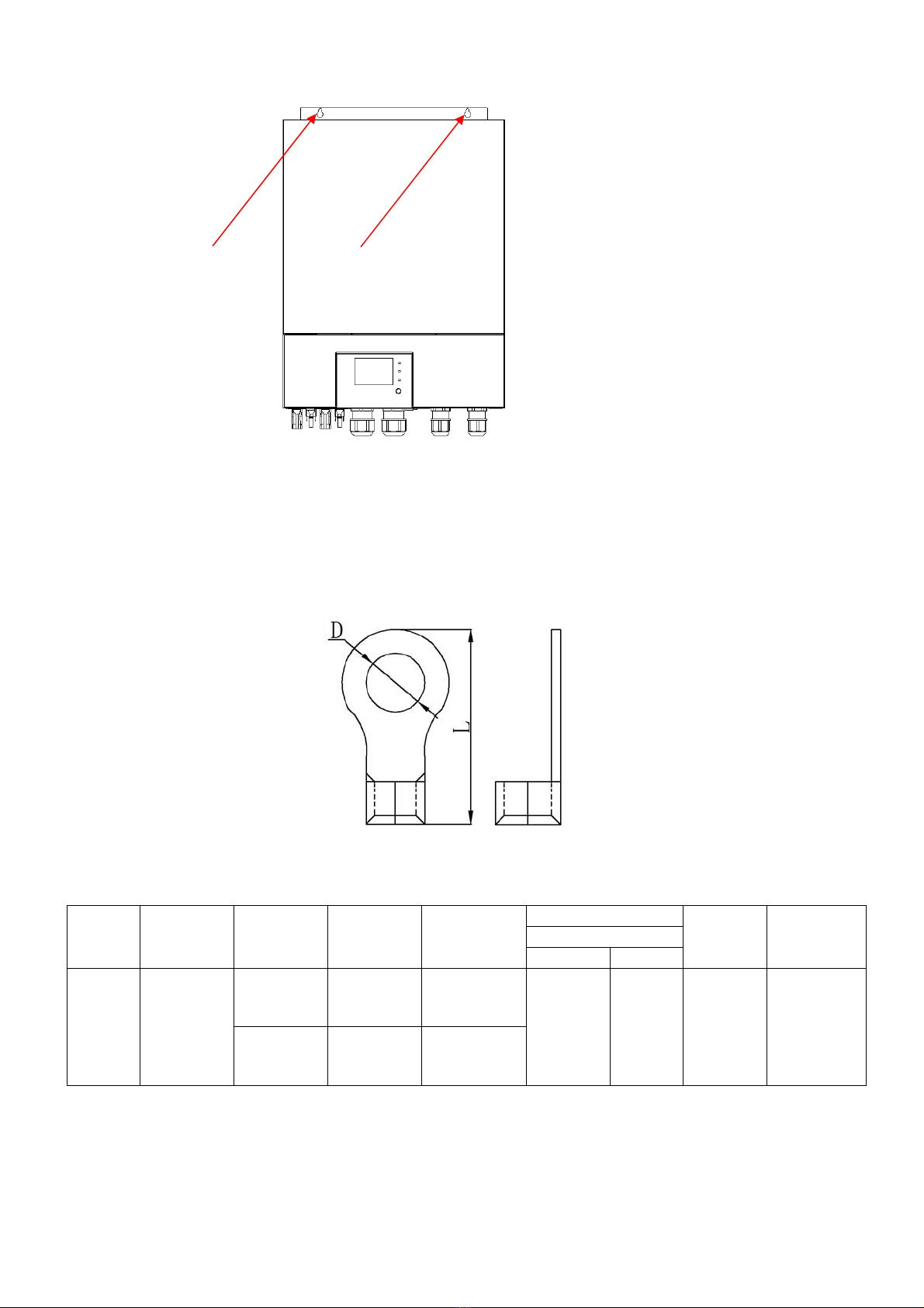
7.For optimum operation of this inverter/charger, please follow required spec to select appropriate cable size.
It’s very important to correctly operate this inverter/charger.
8.Be very cautious when working with metal tools on or around batteries. A potential risk exists to drop a tool
to spark or short circuit batteries or other electrical parts and could cause an explosion.
9.Please strictly follow installation procedure when you want to disconnect AC or DC terminals. Please refer
to INSTALLATION section of this manual for the details.
10.Fuses are provided as over-current protection for the battery supply.
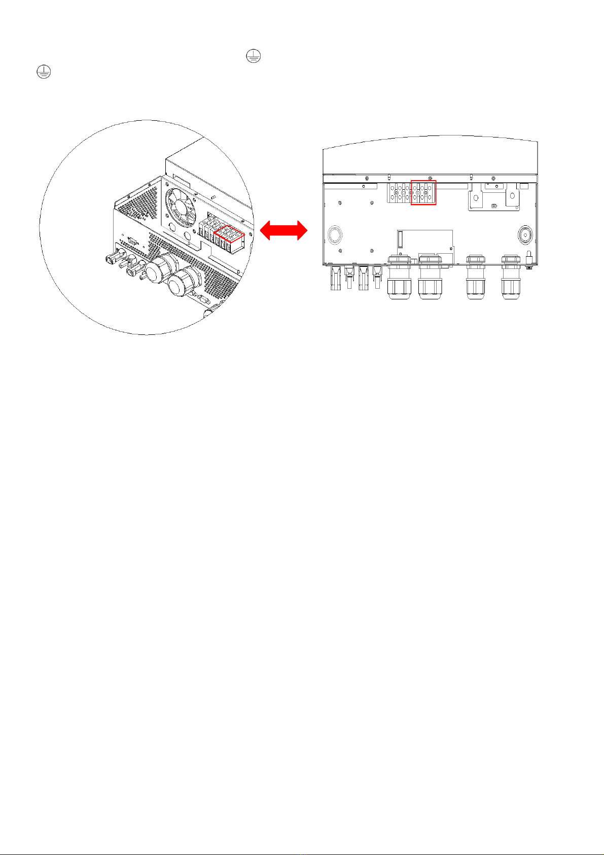
11.GROUNDING INSTRUCTIONS -This inverter/charger should be connected to a permanent grounded
wiring system. Be sure to comply with local requirements and regulation to install this inverter.
12. NEVER cause AC output and DC input short circuited. Do NOT connect to the mains when DC input short
circuits.
13.Warning!! Only qualified service persons are able to service this device. If errors still persist after following
troubleshooting table, please send this inverter/charger back to local dealer or service center for maintenance.
14. WARNING: Because this inverter is non-isolated, only three types of PV modules are acceptable:
single crystalline, poly crystalline with class A-rated and CIGS modules. To avoid any malfunction, do not
connect any PV modules with possible current leakage to the inverter. For example, grounded PV modules will
cause current leakage to the inverter. When using CIGS modules, please be sure NO grounding.
15. CAUTION: It’s required to use PV junction box with surge protection. Otherwise, it will cause damage on
inverter when lightning occurs on PV modules.
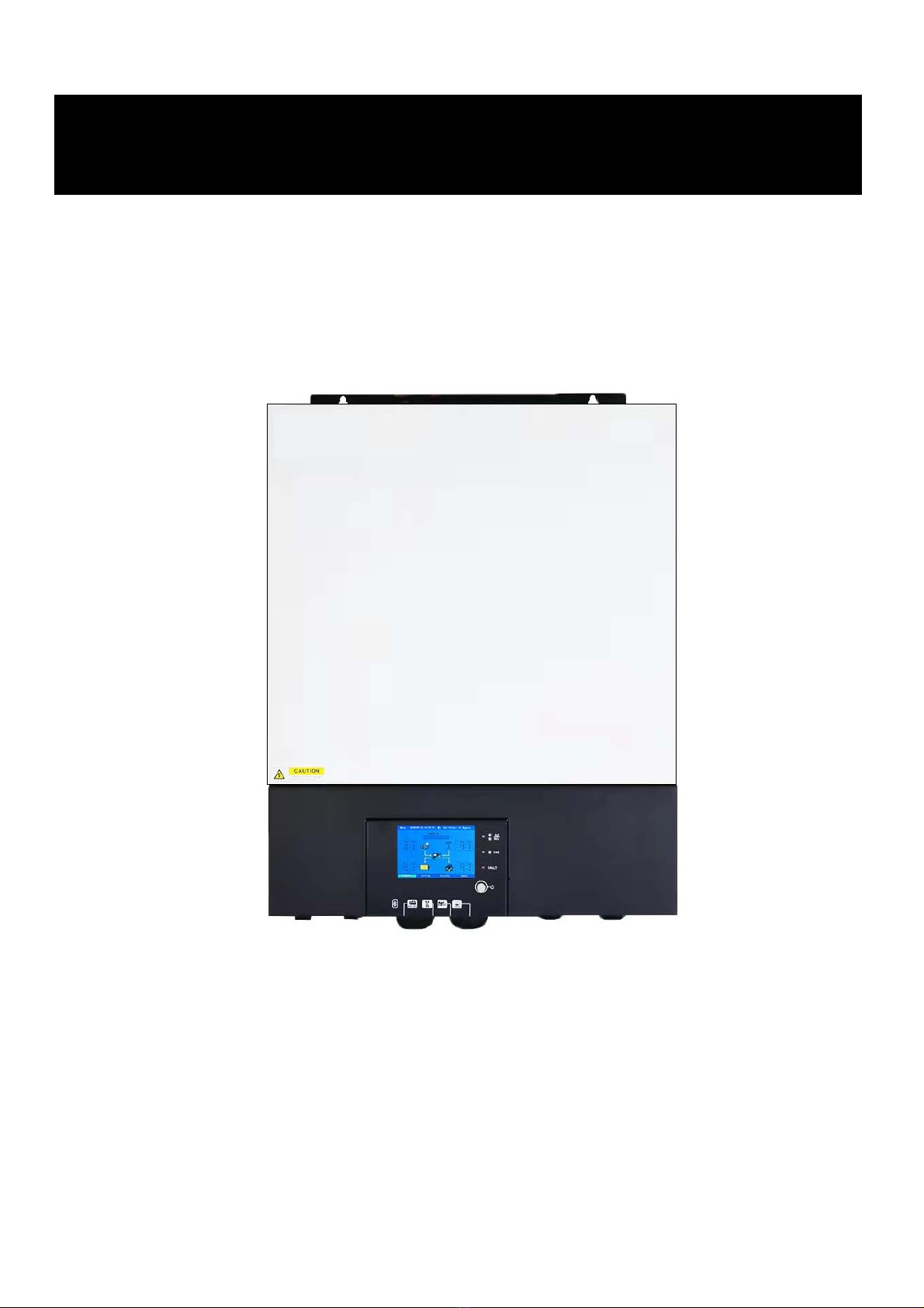
3. Introduction
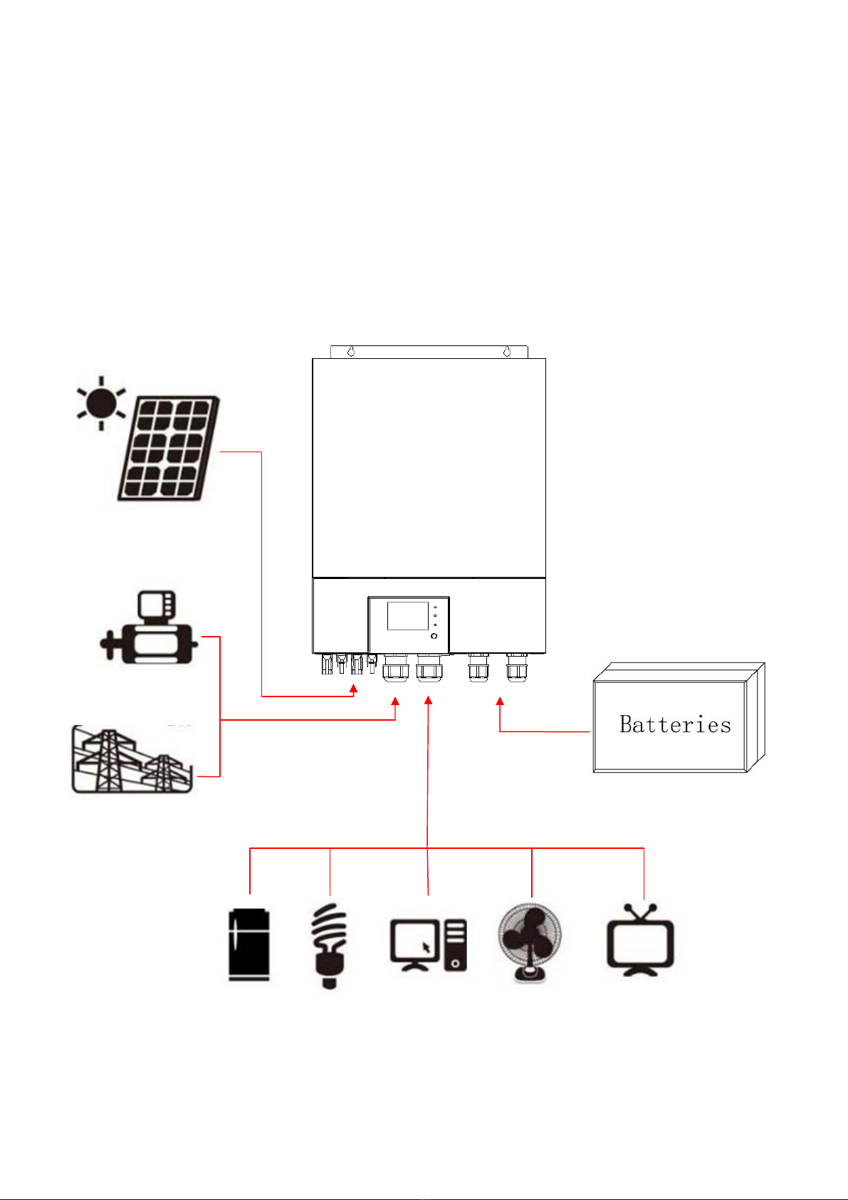
This is a multi-function inverter, combining functions of inverter, solar charger and battery charger to offer
uninterruptible power support in a single package. The comprehensive LCD display offers user-configurable
and easy-accessible button operations such as battery charging current, AC or solar charging priority, and
acceptable input voltage based on different applications.
3.1 Features
1.ON/Off grid inverter
2.Pure sine wave inverter
3. External WIFI devices (APP is required)
4. Communication ports with BMS (RS485, CAN)
5.Support the selection of wide and narrow range of AC input.
6.Configurable AC/Solar charger priority via LCD control panel
7.Configurable battery charging current based on applications via LCD control panel
8.Compatible to utility mains or generator power
9.Auto restart while AC is recovering
10.Overload / Over temperature / short circuit protection
11.Cold start function

2
3.2 Basic System Architecture
The following illustration shows basic application for this unit. It also required the following devices to have a
complete running system:
Generator or Utility
mains.
PV
modules
Consult with your system integrator for other possible system architectures depending on your requirements.
This inverter can power various appliances in home or office environment, including motor-type appliances
such as tube light, fan, refrigerator and air conditioners.
NOTE: The following picture is only a schematic diagram of the equipment .If the actual chassis does not
conform to the schematic due to a structural upgrade, it is subject to prior notice.
Figure 1 Basic hybrid PV System O
verview
Solar power
Generator
Or
Utility Load
Battery packs

3
3.3 Product Overview
NOTE: The following picture is only a schematic diagram of the equipment .If the actual chassis does not
conform to the schematic due to a structural upgrade, it is subject to prior notice.
1: Remote LCD module communication port 2: Generator dry contact
3: USB port 4: RS485 port/CAN port
5: RS232 port 6: Battery positive
7: Battery negative 8: Parallel port
9: Current sharing port 10: PV1 negative connector
11: PV1 positive connector 12: PV2 negative connector
13: PV2 positive connector 14: WIFI port
15: Power on/off switch 16:AC input connector
17:AC output connector
Note: RS485,CAN communication share the same port ,so it can’t be used at the same time.
Communication port definition:
RS232 1:RXD , 2:TXD,8:GND
RS485 6:485-B ,7.485-A
CAN 3:CAN-H,5:CAN-L

4
4. Installation
4.1 Unpacking And Inspection
Before installation, please inspect the unit. Be sure that nothing inside the package is damaged. You should
have received the following items inside of package:
The inverter x1
User manual x 1
RS232 Communication cable x1
USB Communication cable x 1
Parallel communication cable x 1(No parallel machine ,No need)
Current sharing cable x 1 (No parallel machine ,No need)
PV connectors x 2 sets
4.2 Preparation
Before connecting all wire, please take off bottom cover by removing two screws.
NOTE: The following picture is only a schematic diagram of the equipment .If the actual chassis does not
conform to the schematic due to a structural upgrade, it is subject to prior notice.
4.3 Mounting The Unit
Consider the following points before selecting where
to install:
1.Do not mount the inverter on flammable construction
materials.
2.Mount on a solid surface
3.Install this inverter at eye level in order to allow the
LCD display to be read at all times.
4.The ambient temperature should be between -10°C
and 55°C to ensure optimal operation.
5.The recommended installation position is to be adhered
to the wall vertically.
6.Be sure to keep other objects and surfaces as shown
in the right diagram to guarantee sufficient heat dissipation
and to have enough space for removing wires.
WARNING:SUITABLE FOR MOUNTING ON CONCRETE OR OTHER NON-COMBUSTIBLE SURFACE
ONLY.
50cm
50cm
20cm 20cm

5
Install the unit by screwing four screws. It’s recommended to use M4 or M5 screws.
4.4 Battery Connection
CAUTION: For safety operation and regulation compliance, it’s requested to install a separate DC over-current
protector or disconnect device between battery and inverter. It may not be requested to have a disconnect
device in some applications, however, it’s still requested to have over-current protection installed. Please refer
to typical amperage in below table as required fuse or breaker size.
WARNING! All wiring must be performed by a qualified personnel.
WARNING! It's very important for system safety and efficient operation to use appropriate cable for battery
connection. To reduce risk of injury, please use the proper recommended cable and terminal size as below.
Recommended battery cable and terminal size:
Ring terminal:
Model
Typical
Amperage
Battery
capacity
Wire Size Cable mm2Ring Terminal
Torque
value Length
Dimensions
D (mm) L (mm)
8KW 190.5A
100AH
1AWG
50
8.4
51
5 Nm 1M
200AH 1/0AWG 70
Please follow below steps to implement battery connection:
1. Assemble battery ring terminal based on recommended battery cable and terminal size.
2. Fix two cable glands into positive and negative terminals.

6
48VDC battery connection diagram
3. Insert the ring terminal of battery cable flatly into battery connector of inverter and make sure the nuts are
tightened with torque of 5 Nm. Make sure polarity at both the battery and the inverter/charge is correctly
connected and ring terminals are tightly screwed to the battery terminals.
WARNING: Shock Hazard
Installation must be performed with care due to high battery voltage in series
CAUTION!! Do not place anything between the flat part of the inverter terminal and the ring terminal.
Otherwise, overheating may occur.
CAUTION!! Do not apply anti-oxidant substance on the terminals before terminals are connected tightly.
CAUTION!! Before making the final DC connection be sure positive (+) must be connected to positive (+) and
negative (-) must be connected to negative(-).

7
4.5 AC Input/output Connection
CAUTION!! Before connecting to AC input power source, please install a separate AC breaker between
inverter and AC input power source. This will ensure the inverter can be securely disconnected during
maintenance and fully protected from over current of AC input.
CAUTION!! Please refer to the input and output screen on the machine before wiring, make sure correct wiring.
WARNING! All wiring must be performed by a qualified personnel.
WARNING! It's very important for system safety and efficient operation to use appropriate cable for AC input
connection. To reduce risk of injury, please use the proper recommended cable size as below. Suggested
cable requirement for AC wires
Model
Gauge
Torque Value
8KW
8
AWG
1.4~ 1.6Nm
Please follow below steps to implement AC input/output connection:
1. Before making AC input/output connection, be sure to protector disconnected first.
2. Remove insulation sleeve 10mm for six conductors. And shorten phase L and neutral conductor N 3 mm.
3. Fix two cable glands into input and output sides.
4. Insert AC input wires according to polarities indicated on terminal block and tighten the terminal screws.
Be sure to connect PE protective conductor ( ) first.
→Ground (yellow-green)
L→LINE (brown or black)
N→Neutral (blue)
WARNING:
Be sure that AC power source is disconnected before connect wire to the unit.

8
5. Then, insert AC output wires according to polarities indicated on terminal block and tighten terminal screws.
Be sure to connect PE protective conductor ( ) first.
→Ground (yellow-green)
L→LINE (brown or black)
N→Neutral (blue)
6. Make sure the wires are securely connected.
CAUTION: Important
Be sure to connect AC wires with correct polarity. If L and N wires are connected reversely, it may cause
utility short-circuited when these inverters are worked in parallel operation.
CAUTION: Appliances such as air conditioner requires at least 2~3 minutes to restart because it’s required to
have enough time to balance refrigerant gas inside of circuits. If a power shortage occurs and recovers in a
short time, it will cause damage to your connected appliances. To prevent this kind of damage, please check
manufacturer of air conditioner if it’s equipped with time-delay function before installation. Otherwise, this
inverter/charger
will be trigger overload fault and cut off output to protect your appliance but sometimes
it still causes internal damage to the air conditioner.
4.6 PV Connection
CAUTION: Before connecting to PV modules, please install separately DC circuit breakers between inverter
and PV modules.
CAUTION: It is forbidden for inverter to share the same solar panel group.
NOTE1: Please use 600Vdc/30A circuit breaker.
NOTE2: The overvoltage category of the PV input is II.
Please follow the steps below to implement PV module connection:
WARNING: Because this inverter is non-isolated, only three types of PV modules are acceptable: single
crystalline and poly crystalline with class A-rated and CIGS modules.
To avoid any malfunction, do not connect any PV modules with possible current leakage to the inverter. For
example, grounded PV modules will cause current leakage to the inverter. When using CIGS modules, please
be sure NO grounding.
CAUTION: It’s required to use PV junction box with surge protection. Otherwise, it will cause damage on
inverter when PV modules are struck by lightning.
Step 1:Check the input voltage of PV array modules. This system is applied with two strings of PV array.
Please make sure that the maximum current load of each PV input connector is 18A.
CAUTION: Exceeding the maximum input voltage can destroy the unit!! Check the system before wire
connection.
Step 2: Disconnect the circuit breaker and switch off the DC switch.
Step 3: Assemble provided PV connectors with PV modules by the following steps.

9
Components for PV connectors and Tools:
Female connector housing
Female terminal
Male connector housing
Male terminal
Crimping tool and spanner
Prepare the cable and follow the connector assembly process:
Strip one cable 8 mm on both end sides and be careful NOT to nick conductors.
Insert striped cable into female terminal and crimp female terminal as shown below.
Insert assembled cable into female connector housing as shown below.
Insert striped cable into male terminal and crimp male terminal as shown below.
Insert assembled cable into male connector housing as shown below.

10
Step 4: Check correct polarity of connection cable from PV modules and PV input connectors. Then, connect
positive pole (+) of connection cable to positive pole (+) of PV input connector. Connect negative pole (-) of
connection cable to negative pole (-) of PV input connector.
WARNING! For safety and efficiency, it's very important to use appropriate cables for PV module connection.
To reduce risk of injury, please use the proper cable size as recommended below.
CAUTION: Never directly touch the terminals of inverter. It might cause lethal electric shock.
PV1 Connection
PV2 Connection
Model Cable (mm2)AWG Torque value(max)
8KW 4 12 1.2-1.6 Nm

11
Recommended Panel Configuration
When selecting proper PV modules, please be sure to consider the following parameters:
1. Open circuit Voltage (Voc) of PV modules not to exceed maximum PV array open circuit voltage of the
inverter.
2. Open circuit Voltage (Voc) of PV modules should be higher than the start-up voltage.
INVERTER MODEL
8KW
Max. PV Array Power
4000W*2
Max. PV Array Open Circuit Voltage
450Vdc
PV Array MPPT Voltage Range
120Vdc~450Vdc
Recommended solar panel configuration:
Solar Panel Spec.
(reference)
- 250Wp
- Vmp: 30.7Vdc
- Imp: 8.3A
- Voc: 36Vdc
- Isc: 8.4A
- Cells: 60
SOLAR INPUT 1 SOLAR INPUT 2 Q'ty of panels
Total Input Power
Min. in series: 4pcs, per input
Max. in series: 12pcs, per input
4pcs in series
x
4pcs
1000W
x
4pcs in series
4pcs
1000W
12pcs in series
x
12pcs
3000W
x
12pcs in series
12pcs
3000W
6pcs in series 6pcs in series
12pcs
3000W
6pcs in series,
2
strings
x
12pcs
3000W
x
6pcs in series,
2
strings
12pcs
3000W
8pcs in series,
2
strings
x
16pcs
4000W
x
8pcs in series,
2
strings
16pcs
4000W
9pcs in series, 1 string 9pcs in series, 1 string
18pcs
4500W
10pcs in series,
1
string
10pcs in series,
1
string
20pcs
5000W
12pcs in series,
1
string
12pcs in series,
1
string
24pcs
6000W
6pcs in series,
2
strings
6pcs in series,
2
strings
24pcs
6000W
7pcs in series,
2
strings
7pcs in series,
2
strings
28pcs
7000W
8pcs in series,
2
strings
8pcs in series,
2
strings
32pcs
8000W

12
4.7 Final Assembly
After connecting all wirings, re-connect three cables and then put bottom cover back by screwing two screws
as shown below.
4.8 RS232/USB Communication Connection
Please download software “SolarPower” from the official website. When the inverter is connected to the
computer, the following interface will be displayed.
Note: The following dates are for reference only.
4.9 Wi-Fi Connection
(
Optional
)
1. The device has its own standard WIFI port, if users need to monitor the status and information of the device
through WIFI, they must connect to the WIFI collector.
2. Users can download”SmartEss” WIFI monitoring software from the app store on their phone.
3. Inverters come equipped with factory-integrated Wi-Fi capability which makes it very easy to integrate into a
home network (Wi-Fi Dongle is Optional) this makes it ideal for local monitoring via the inverter’s own wireless
home network or for online monitoring platforms
.

13
4.10 Dry Contact Signal
There is one dry contact (3A250VAC) available on the rear panel. It could be used to deliver signal to external
device when battery reaches warning level.
Unit Status Condition
NC & C C & NO
Power Off Unit is off and no output is powered Open Close
Power On Battery voltage <Setting the voltage in program 12 Close Open
Battery voltage >Setting the voltage in program 13 Open Close
4.11 Bluetooth Communication (Optional)
This unit is equipped with a Bluetooth transmitter. Download “RevoMonitor” APP from Google Play . Once
the APP is download, you may connect “RevoMonitor” APP to your inverter with the pairing password “1234”.
The communication distance is roughly 6 ~ 7 meters.
Note:1.the following date are for reference only.
2.Bluetooth APP only supports Android phone users.

14
5. Operation
5.1 Power ON/OFF
Once the unit has been properly installed and the batteries are connected well, simply press On/Off
switch(located on the button of the case) to turn on the unit.
5.2 Operation And Display Panel
The operation and display panel, shown in below chart, is on the front panel of the inverter. It includes three
indicators, four function keys and a LCD display, indicating the operating status and input/output power
information.
1. PV input information 2. Operation information
3. AC/INV indicator 4. AC Input information
5. Charging indicator 6. AC Output information
7. Fault indicator 8. About button
9. History button 10. Setting button
11. Diagram button 12. Battery information
PV1/PV2

15
5.3 LCD Display Icons
Icon
Description
operation time
Operation information include fault and warning code
Input voltage ,current and power information
Output voltage ,current and power information
PV input voltage , PV input current ,PV input power information
NOTE: the information of PV1 and PV2 is automatically switched every 3 seconds
Battery voltage ,current and power information
Indicates the DC/AC inverter circuit is working
Parallel status
Explain: “PAR”:Parallel mode , “M”:Host, “S”:Slave
“01”:Parallel number
Grid mode is enable
PV1/PV2
Grid

16
Inverter working status
Battery mode run status: Bat inv
Utility mode run status: AC Bypass
PV +Utility mode run status: PV+AC
Volume icon
LCD Version,
Inverter Version,
Mppt Version,
Machine Type
This button includes generation,event,help
language,working mode,input,output ,
battery,charge, PV,parallel,date and time,Grid ,peak valley,
and other
work state diagram
5.4 LCD Setting
After press function button, the unit will enter setting mode. Set password: 1155
Setting
Language Work Mode Input Output
Battery Charge PV Parallel
Date&Time Grid Res. Other
Exit

17
item
menu description
Language
Default: English
Work Mode
AC :(default) AC will provide power to the
loads as the priority, solar charging the
battery. When solar energy is insufficient,
AC and solar energy charge the battery at
the same time. When AC is unavailable, it
will be powered by solar energy or
batteries.
Solar: (option) solar energy provides
power to the loads as the priority. When
the solar energy is sufficient, the extra
energy will charges the battery. When
solar energy is insufficient for load,
batteries and solar will
supplies power
the
loads
at the
same time.
When solar energy
and batteries are insufficient or solar
energy is unavailable, AC power to the
loads and charge the battery at the same
time.
Battery:(option) Battery provides power
to the loads as the priority. AC provides
power to the loads when battery voltage
drop to low-level warning voltage or
setting point, and the AC power will
charge the battery. When the battery is
fully charged, battery provides power to
the loads again.
AC+PV: (option) solar energy provides
power to the loads as the priority. If solar
energy is not sufficient to power all loads,
AC energy will supply power to the loads
at the same time.
Input
Wide range : (default)
AC input voltage range will be within 90-
280VAC.
Narrow range: (option)
AC input voltage range will be within 170-
280VAC.

18
Output
220V(option)
230V(default)
240V(option)
50HZ(default)
60HZ(option)
Battery
1.Lead
acid battery(default)
2.Lithium(option)
3.No Bat: no battery(option)
4.User: (option)
4.1. If “User-Defined” is selected, Bulk
charging voltage and Floating charging
voltage, setting range: 48.0V to 60V,
Increment of each click is 0.1V.
4.2. if you have a lithium battery, you can
choose this option.
4.3.if the BMS communication is
connected between the inverter and the
lithium battery, the display battery icon will
display “USER”.
Battery
1.Low Vol Disconnect:
Setting voltage point back to utility source
when selecting “Solar” or “Battery”.
setting range :44.0V to 51V, Increment of
each click is 0.1V.
2. Shutdown Vol
Setting range is from 42.0V to 48.0V.
Increment of each click is 0.1V.
3. High Vol Reconnect:
Setting voltage point back to battery mode
when selecting “Solar” or “Battery” .setting
range: 48.0V to 58V, Increment of each
click is 0.1V.
This manual suits for next models
1
Table of contents
Other APT Inverter manuals