Aqua HC151+CST User guide

HC151+CST / HC151+PImA / HC200+CST
ENGLISH
USE AND MAINTENANCE INSTRUCTIONS MANUAL FOR DOSING PUMP
HC151+CST HC151+PImA HC200+CST

HC151+CST / HC151+PImA / HC200+CST
ENGLISH
2

HC151+CST / HC151+PImA / HC200+CST
ENGLISH
3
INDEX
1. GENERAL RULES..................................................................................................................................... 4
1.1 SHIPPING AND TRANSPORTING THE PUMP ................................................................................. 4
1.2 INSTALLATION STANDARDS ........................................................................................................... 4
1.3 PROPER USE OF THE PUMP ........................................................................................................... 4
2. OPERATION .............................................................................................................................................. 6
2.1 OVERALL DIMENSIONS.................................................................................................................... 6
2.2 TECHNICAL FEATURES.................................................................................................................... 6
2.3 HYDRAULIC FEATURES ................................................................................................................... 7
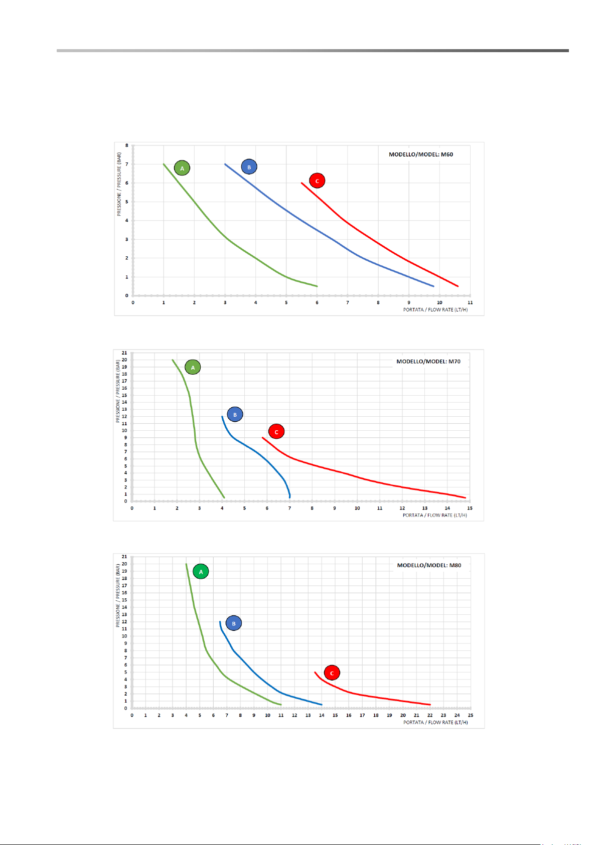
2.4 PERFORMANCE GRAPHS ................................................................................................................ 8
2.4.1 grafici relativi alle versioni a 230V ..................................... Errore. Il segnalibro non è definito.
2.5 CONTENT OF THE PACKAGE .......................................................................................................... 9
3. HC151+CST/HC200+CST....................................................................................................................... 10
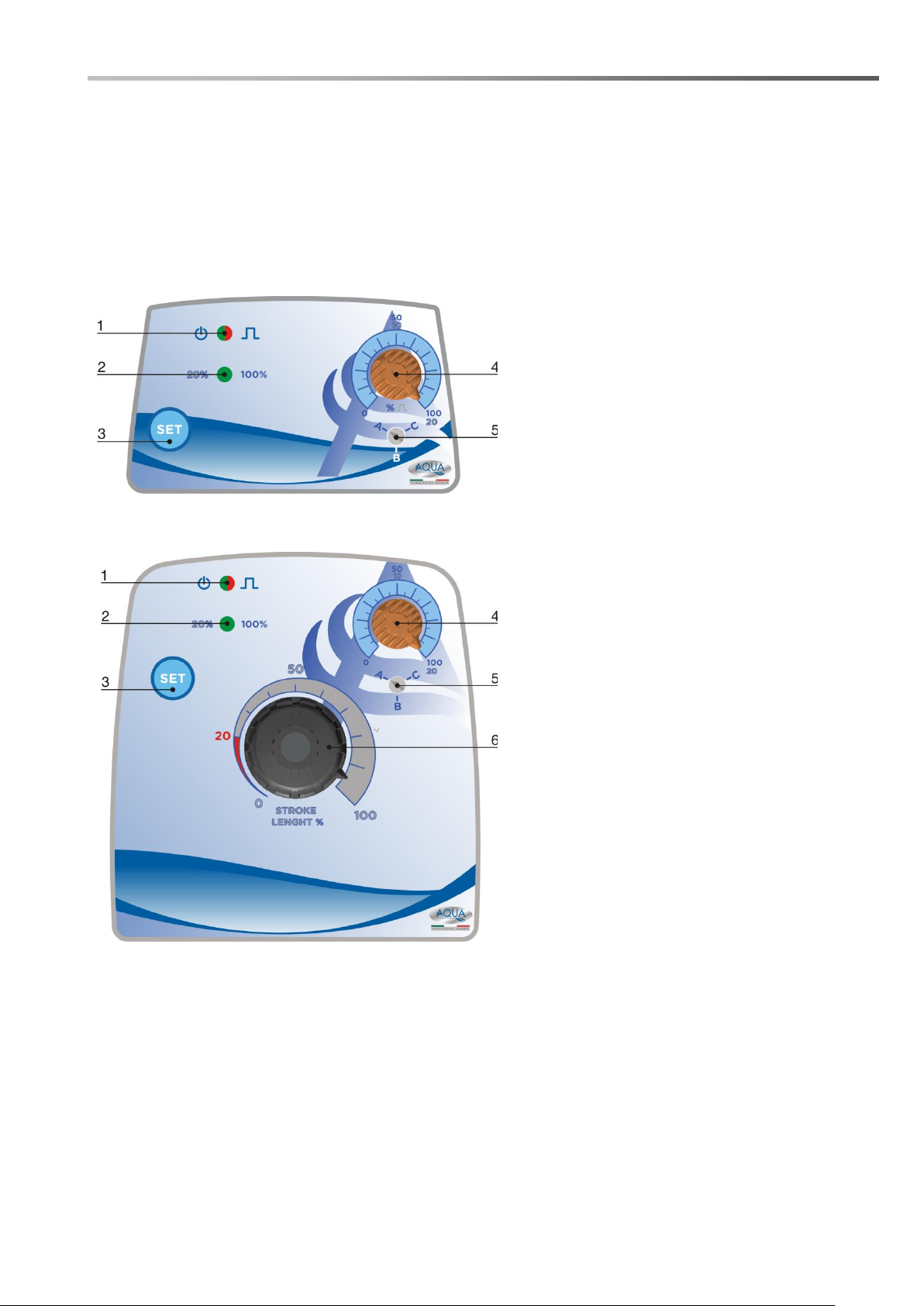
3.1 HC151+CST/HC200+CST PUMP CONTROLS ............................................................................... 10
3.2 HC151+CST/HC200+CST OPERATING MODE ............................................................................. 10
3.3 MODIFICATION OF PUMP PERFORMANCE ................................................................................. 11
4. HC151+PImA........................................................................................................................................... 12
4.1 HC151+PImA PUMP CONTROLS ................................................................................................... 12
4.2 MODIFICATION OF PUMP PERFORMANCE ................................................................................. 12
4.3 HC151+PImA OPERATING MODE.................................................................................................. 13
4.5 HOW TO CHOOSE THE PERFORMANCES OF A PUMP .............................................................. 14
4.6 HOW TO CALCULATE THE MULTIPLICATION VALUE (1xN) ....................................................... 14
4.7 HOW TO CALCULATE THE DIVISION VALUE (1:N) ...................................................................... 14
5. DOSING PUMPS INSTALLATION RULES............................................................................................. 15
6. ELECTRICAL CONNECTIONS ............................................................................................................... 16
6.1 HC151+ PImA model pump .............................................................................................................. 16
5.1 CHOICE OF THE PUMP VOLTAGE................................................................................................. 16
7. TROUBLESHOOTING ............................................................................................................................. 17
7.1 PROBLEM –CAUSE –SOLUTION.................................................................................................. 17
8. CLEANING AND MAINTENANCE .......................................................................................................... 17
8.1 CLEANING THE PUMP .................................................................................................................... 17
8.2 PUMP MAINTENANCE..................................................................................................................... 18
9. WARRANTY............................................................................................................................................. 18
EXPLODED VIEWS ........................................................................................................................................ 20

HC151+CST / HC151+PImA / HC200+CST
ENGLISH
4
1. GENERAL RULES
Carefully read the warnings listed below as they provide important information regarding the rules for
installation, use and maintenance.
Please keep this manual carefully for further reference.
1.1 SHIPPING AND TRANSPORTING THE PUMP
The equipment must be transported in its original packaging, organized and built in such a way as to
minimize shocks and to protect the protruding parts that can be damaged. If there is a need for transport
after the equipment has already been installed (e.g. for a return for repair or replacement), reuse the
original packaging or a sufficiently sturdy packaging with the equipment protected with absorbent
material ( eg bubble wrap). The external packaging must be such as to ensure the safety of the
equipment in the event of a fall from 1 meter in height.
1.2 INSTALLATION STANDARDS
Install the dosing pump so that it is easily accessible whenever maintenance is required. Never
obstruct the place where the dosing pump is located.
The servicing and maintenance of the dosing pump and all its accessories must always be carried out
by qualified personnel.
AQUA SpA cannot be held responsible for damage to persons or things caused by poor installation or
incorrect use of the dosing pump.
Check that the ground is fully functional and corresponds to the regulations in force. Make sure
there is a high sensitivity differential switch (0.03 A). Check that the pump ratings are compatible
with those of the mains supply. Never install the pump directly in parallel with inductive loads
(eg motors / solenoid valves) but if necessary use an "insulation relay". Inside the pump there
are two protections: a varistor and a fuse.
1.3 PROPER USE OF THE PUMP
The use of this pump must comply with the methods and instructions set out in this manual.
The pump can dose chemicals that can be harmful to human health and for this reason it is essential that must
be used by qualified personnel who adopt the appropriate safety methods and personal protective equipment.
AVOID IMPROPER USE of the equipment in order to avoid damage to things and people, due to uncontrolled
splashes, drips, electrical contacts, etc.
The following uses can be considered improper uses, in indicative and non-exhaustive form:
- Dosing of products not consistent with the materials with which the pump is made;
- Dosing of explosive and / or flammable products;
- Dosing of fluids with excessive viscosity (1000 cps), such as to prevent the priming of the pump itself;
- Dosage of food liquids, if intended to maintain such use;
P: dosing pump
R: relay
I : Switcher or multi-pole
security device
E: Motor or generally
inductive charge
A: supply voltage

HC151+CST / HC151+PImA / HC200+CST
ENGLISH
5
- Avoid inverting the pump delivery and suction;
- Avoid powering the pump with voltages other than those indicated in the technical specifications;
- Avoid connecting any equipment other than specific equipment to the signal outputs (level, pulse
counter, current signal, etc.);

HC151+CST / HC151+PImA / HC200+CST
ENGLISH
6
2. OPERATION
The HC151+ CST HC200+ CST and HC151+ PImA analogue pumps are solenoid driven dosing pumps that
can operate at constant flow (CST version) or at proportional flow according to an external signal (PI-mA
version). Depending on the model, there may be: a BNC connector for connecting a level sensor and / or a 4-
pole connector for connection to a current signal (mA) or from a pulse-emitting water meter.
2.1 OVERALL DIMENSIONS
HC151+
HC200+
2.2 TECHNICAL FEATURES
Power supply: 100÷240VAC ± 10% –50/60Hz
Insulation Class: CLASS I
Absorbed power: see “2.3 - Hydraulic Features”
Fusible: 2 A –RIT
Protection Grade: IP65
Environmental conditions: Closed environment, altitude up to 2000m, room temperature from
5°C up to 40°C, maximum relative humidity 80% (linearly decreases
until it is reduced to 50% at 40°C).
THE EQUIPMENT, SUBJECT TO THIS DOCUMENT, ARE NOT
INTENDED TO BE INSTALLED AND USED IN EXPLOSIVE
ATMOSPHERE ENVIRONMENTS. IT ISN’T AN ATEX PUMP.

HC151+CST / HC151+PImA / HC200+CST
ENGLISH
7
2.3 HYDRAULIC FEATURES
Hydraulic characteristics of the 230V version
SOLENOID
TYPE
FLOW RATE
PRESSURE
STROKES
INJECTION
VALUE
ABSORBED
POWER
l/h
bar
spm
ml/stroke
Watt
60
A
1
7
100
0,17
13
5
1
0,83
13
B
3
7
150
0,33
16
9
1
1
16
C
5,5
6
180
0,51
22
10
1
0,93
22
70
A
1,8
20
75
0,40
18
4
1
0,89
18
B
4
12
120
0,56
25
7
1
0,97
25
C
5,8
9
180
0,54
27
14
1
1,30
27
80
(only HC151)
A
4
20
150
0,44
24
10
1
1,11
24
B
6,5
12
200
0,54
27
13
1
1,08
27
C
13,5
5
300
0,75
35
20
1
1,11
35
The above data refer to tests carried out with water at room temperature. Values can fluctuate by 10%.
With chemical products with a different viscosity than that of water, the flow rate data may undergo even
sensitive variations.
Hydraulic characteristics of the 110V version
SOLENOID
TYPE
FLOW RATE
PRESSURE
STROKES
INJECTION
VALUE
ABSORBED
POWER
l/h
bar
spm
ml/stroke
Watt
60
A
1,5
7
100
0,25
18
5
1
0,83
18
B
4,5
7
150
0,5
23
7
1
0,78
23
C
6
6
180
0,56
28
8,8
1
0,81
28
70
A
1
20
75
0,22
21
4,5
1
1
21
B
4
12
120
0,56
31
7
1
0,97
31
C
6,8
9
180
0,63
41
10,8
1
1
41
80
(only HC151)
A
3
17
150
0,33
27
10
1
1,11
27
B
7,5
12
200
0,63
36
13
1
1,08
36
C
11
5
230
0,80
44
16
1
1,16
44
The above data refer to tests carried out with water at room temperature. Values can fluctuate by 10%.
With chemical products with a different viscosity than that of water, the flow rate data may undergo even
sensitive variations.

HC151+CST / HC151+PImA / HC200+CST
ENGLISH
8
2.4 PERFORMANCE GRAPHS
2.4.1 graphs relating to the 230V versions

HC151+CST / HC151+PImA / HC200+CST
ENGLISH
9
2.4.2 graphs relating to the 110V versions
2.5 CONTENT OF THE PACKAGE
▪HC151+pump
▪User’s manual
▪Injection valve PP-GL-VT (PVDF-CE-VT only for PI-mA model)
▪Foot filter PP-GL-VT (PVDF-CE-VT only for PI-mA model)
▪2 meters PE discharge tube
▪2 meters PVC suction tube

HC151+CST / HC151+PImA / HC200+CST
ENGLISH
10
▪2 meters PVC bleed valve tube (2 m)
▪Fixing bracket
▪Set of screws and plugs for wall mounting
3. HC151+ CST/HC200+ CST
3.1 HC151+CST/HC200+CST PUMP CONTROLS
The HC151 + CST pump control panel looks like this:
HC151+
HC200+
3.2 HC151+CST/HC200+CST OPERATING MODE
The pump can works in the following mode:
•ON-OFF Mode
- the pump doses at a constant frequency based on the percentage set using the strokes frequency
knob (4)
When it turns on for the first time the pump is set, by default, in Stand-by (green LED (1) steady)
with 100% scale frequency (green LED (2) steady).
To activate the pump, press and hold the SET (3) button for 2 seconds, the pump will start to work
(red LED (1) flashing) at the frequency set using the hand knob (4); to stop the pump press and hold
the SET button for 2 seconds
1. Green/Red LED Stand-by/Pulse;
2. Green LED stroke frequency scale;
3. Function/Enter button;
4. Strokes frequency hand knob;
5. Pump performances selector;
6.Stroke lenght adjustment knob (only for
HC200+).

HC151+CST / HC151+PImA / HC200+CST
ENGLISH
11
To change the scale frequency from 100% to 20% press SET (3) button; ATTENTION: the selection
of the frequency scale can be performed only when the pump is in stand-by mode.
NOTE: after a power failure the pump will return to the state prior to the power failure (Eg: if the pump
was operating at the time of the power failure, on its return, the pump will continue working).
3.3 MODIFICATION OF PUMP PERFORMANCE
The HC151+/HC200+ pumps are equipped with a selector (5) on the control panel which allows greater
flexibility in the choice of the performances obtainable from the pump.
The function of the selector is described below:
1. Switch off the dosing pump;
2. By means of a flat screwdriver, rotate the
selector from its actual position to the destre one
(A-B-C), each one corresponding to the datas of
“2.3 - HYDRAULIC FEATURES” on pag. 21,
depending on pump model chosen (solenoids 60,
70 or 80);
3. Switch on the dosing pump.
Example:

HC151+CST / HC151+PImA / HC200+CST
ENGLISH
12
4. HC151+ PImA
4.1 HC151+PImA PUMP CONTROLS
The HC151+ PImA pump control panel looks like this:
4.2 MODIFICATION OF PUMP PERFORMANCE
The HC151+/ pump is equipped with a selector (9) on the control panel which allows greater flexibility in the
choice of the performances obtainable from the pump.
The function of the selector is described below:
1. Green/Red LED, Stand-by/Pulse;
2. Orange LED, Level alarm;
3. Green/Red LED, frequency scale (green),
divider 1:1000 (red);
4. Green/Red LED, 4-20mA signal (green),
divider 1:100 (red);
5. Green/Red LED, multiplier (green), divider
1:10 (red);
6. Function/Enter button;
7. Red LED, divider 1:1;
8. Strokes frequency hand knob/multiplier-
divider scale 1/10/100/1000;
9. Pump performances selector
1. Switch off the dosing pump;
2. By means of a flat screwdriver, rotate the selector
from its actual position to the destre one (A-B-C),
each one corresponding to the datas of “2.3 -
HYDRAULIC FEATURES” on pag. 21, depending
on pump model chosen (solenoids 60, 70 or 80);
3. Switch on the dosing pump.
Example:

HC151+CST / HC151+PImA / HC200+CST
ENGLISH
13
4.3 HC151+PImA OPERATING MODE
The pump can operate in one of the following modes,
which can be selected by pressing the SET button:
1. When it turns on for the first time the pump is set, by
default, in Stand-by (green LED (1) steady) with
100% scale frequency (green LED (3) steady), press
SET button to move to the next function;
2. Green LED flashing (3),20% scale frequency, this
means the function it has been selected. It is now
possible to obtain a more precise adjustment of the
percentage of strokes using the hand knob (8) is
used, press the SET button to move to the next
function;
3. Green LED (4) steady, 4-20mA proportional
functioning: the mA current supplied to the pump
(via an input signal) will determine the proportional
dosage. By means the hand knob (8) it is possible to
set the max frequency of the pump (in percentage)
associated to the maximum mA current value (which
it is 20 mA) (ex.: hand knob (8) set on 50%, at 20mA
the pump will works at 50% of the maximum
frequency);
4. Green LED (5) steady, pulse emitting water meter
proportional functioning –1XN multiplier mode:
pulses supplied by water meter, are multiplied by the
value set with the hand knob (8) (from 10 to 100);
5. Red LED (7) steady, pulse emitting water meter
proportional functioning –1:N divider mode –
(divider mode 1÷1): a pulse provided by the water
meter generates a strokes from the pump.
6. Red LED (5) steady, pulse emitting water meter
proportional functioning –1:N divider mode –
(divider mode 1÷10): pulses provided by a water
meter, are divided (from 1 to 10) by means the hand
knob (8).
7. Red LED (4) steady, pulse emitting water meter
proportional functioning –1:N divider mode –
(divider mode 10÷100): pulses provided by a water
meter, are divided (from 10 to 100) by means the
hand knob (8).
8. Red LED (3) steady, pulse emitting water meter
proportional functioning –1:N divider mode –
(divider mode 100÷1000): pulses provided by a
water meter, are divided (from 100 to 1000) by means
the hand knob (8).
Note: It is advisable to use the "multiplier" mode in the
presence of water meters that provide few pulses and it is
necessary to multiply them to allow the pump to dose
correctly.
It is advisable to use the "divider" mode in the presence of
water meters that provide many pulses and it is necessary
to divide them to allow the pump to dose correctly.
ATTENTION: to confirm that you want
to use the selected mode, you must
hold down the SET button for 2
seconds. To return to "selection"
mode, press and hold the SET button
again for 2 seconds.

HC151+CST / HC151+PImA / HC200+CST
ENGLISH
14
4.5 HOW TO CHOOSE THE PERFORMANCES OF A PUMP
Being known the value of m3(cubic meters) of water of the plant to be treated and the quantity of
chemical to be dosed, expressed in ppm (gr / m3), it is possible to define the minimum flow rate (l / h) of
the metering pump required, using the following formula:
𝑙/ℎ = 𝑝𝑝𝑚 × 𝐾 × 𝑚3
1000
Where:
- ppm = quantity of chemical to be dosed, expressed in ppm (gr / m3)
- K = dilution coefficient of the chemical to be dosed. Pure chemical K=1
(Example: Sodium Hypochlorite at 12%; K = 100:12 = 8,3)
- m3= maximum flow rate of the water to be treated expressed in m3
4.6 HOW TO CALCULATE THE MULTIPLICATION VALUE (1xN)
𝑁 = 𝑝𝑝𝑚 × 𝐾
𝑖𝑚𝑝/𝑙 × 𝑐𝑐 × 1000
Where:
- ppm = quantity of chemical to be dosed, expressed in ppm (gr / m3)
- K = dilution coefficient of the chemical to be dosed. Pure chemical K=1
(Example: Sodium Hypochlorite at 12%; K = 100:12 = 8,3)
- pulses/l = pulses per liter supplied by the pulse emitting water meter
- cc = quantity of chemical dosed per single injection from the dosing pump
4.7 HOW TO CALCULATE THE DIVISION VALUE (1:N)
𝑁 = 𝑖𝑚𝑝/𝑙 × 𝑐𝑐
𝑝𝑝𝑚 × 𝐾 × 1000
Dove:
- ppm = of chemical to be dosed, expressed in ppm (gr / m3)
- K = dilution coefficient of the chemical to be dosed. Pure chemical K=1
(Example: Sodium Hypochlorite at 12%; K = 100:12 = 8,3)
- pulses/l = pulses per liter supplied by the pulse emitting water meter
- cc = quantity of chemical dosed per single injection from the dosing pump
If in the calculation of the parameter "N", it results:
▪
N <1 (N less than 1) it is necessary to install a water meter with a higher number of pulses per liter or a
dosing pump with a higher flow rate per injection.
▪
N>1000 (N more than 1000) it is necessary to install a dosing pump with a lower flow rate per injection.

HC151+CST / HC151+PImA / HC200+CST
ENGLISH
15
5. DOSING PUMPS INSTALLATION RULES
Strictly follow the instructions for a correct installation of the dosing pump to avoid malfunctions. The most
frequent cases are described below:
• Locate the pump as shown in Figure 1, bearing in mind that it can be mounted either below or above the level
of the chemical to be dosed within the maximum limit of 2 meters (we suggest 1.5 meters). The injection point
must always be placed higher than the chemical to be injected.
• If the system to be treated works at atmospheric pressure and the chemical tank must absolutely be
positioned higher than the injection point (Figure 2), periodically check the functionality of the injection valve
(I), as its excessive wear could lead to unintentional injection of the chemical into the plant due to gravity (even
with the dosing pump stopped). If the problem persists, insert a counter-pressure valve (V) correctly calibrated
between the dosing pump and the injection point.
• For chemicals that emit aggressive fumes, do not install the pump on top of the tank unless the tank is
hermetically sealed (Figure 3).
Figure 1
Figure 2
Figure 3

HC151+CST / HC151+PImA / HC200+CST
ENGLISH
16
6. ELECTRICAL CONNECTIONS
6.1 HC151+ PImA model pump
The connector on the bottom of the pump allows the connection of an external signal coming from a
pulse emitting water meter or a mA signal. Obviously, if a pulse emitting water meter is connected, a
mA signal cannot be connected and vice versa. The pump is also equipped with a BNC connector for
connecting a level probe (not included in the package).
5.1 CHOICE OF THE PUMP VOLTAGE
The HC151+ CST and HC151+ PIMA pumps can work with two different power supply voltages: 230V
(standard) and 110V. To choose 110V operation it is necessary to open the pump and remove the jumper
shown in the following figures.
ATTENTION: this procedure must be carried out with the pump turned off and disconnected from the
power supply.

HC151+CST / HC151+PImA / HC200+CST
ENGLISH
17
Jumper mounted (standard): version 230V Jumper removed: version 110V
7. TROUBLESHOOTING
The solenoid driven dosing pump is a relatively robust device, therefore the chances of mechanical failures
are low. Sometimes chemical leaks may occur from nipples or loose hose nuts of the pump head or simply
due to breakage of the discharge pipe. If one of the above cases occurs, user has to first disconnect the unit
from the power supply, then replaces the damaged part, cleans the unit from any chemical leaks, then restart
the pump.
7.1 PROBLEM –CAUSE –SOLUTION
Below are listed some of the problems that may occur, the causes and solutions
PROBLEM
POSSIBLE CAUSE
SOLUTION
The pump does not switch on
The pump is not powered
The protection fuse is blown up.
The electronic board is damaged
Connect the pump to the mains.
Replace the fuse.
Replace the electronic board.
The pump does not dose but the
solenoid is working
The foot filter is obstructed.
The suction tube is empty, the
pump is not primed.
Air bubbles in the hydraulic
circuit.
The chemical in use generates
gas
Clean the foot filter.
Repeat the priming procedure.
Check nipples and hoses
Open the bleed valve and let the air
goes out.
Replace the pump head with
automatic bleed version.
The pump does not dose and
the solenoid does not works or
the stroke is greatly muffled.
Crystals formation, valve
occlusion and / or the balls are
blocked.
The injection valve is obstructed
Clean the valves and try to circulate
water instead of the chemical
product.
Replace the valves of the pump
head.
Replace the injection valve.
8. CLEANING AND MAINTENANCE
8.1 CLEANING THE PUMP
The pump must be periodically cleaned in order to ensure its efficiency. We suggest to carry out regular
cleaning during maintenance period.

HC151+CST / HC151+PImA / HC200+CST
ENGLISH
18
Before carrying out any maintenance or cleaning operations on the dosing pump, it is necessary to:
1. Make sure that it is electrically disabled (both polarities) by disconnecting the conductors from the contact
points of the power supply by opening the omnipolar switch;
2. Eliminate in the most appropriate and gradual way, (paying the utmost attention not to generate splashes),
the existing pressure in the pump body and in the delivery pipe, by opening the appropriate air bleed valve.
3. Remove the protective cover of the pump body, to highlight any underlying leaks and encrustations;
4. Clean any incrustations due to leaks or drips on the pump body or on the entire pump structure, paying
particular attention to the lower part of the pump where, usually, any incrustations due to drips accumulate;
5. Reassemble the cover of the pump body, the delivery and suction pipes, close the air bleed valve and
reconnect the pump electrically;
6. Carry out priming if necessary and restore the normal operating status of the pump.
8.2 PUMP MAINTENANCE
Under normal operating conditions, the metering pump should be checked monthly.
To avoid malfunctions or sudden stops, carefully check the following items:
- check that the electrical and hydraulic connections are intact;
- check for any leaks on the connections of the pump head or the injection valve;
- check that there are no parts of the pump or pipes corroded.
Always empty the pump head from chemical, if there could still be presence of dangerous chimica inside the
pump head it is mandatory to declare it filling the RETURN MATERIAL AUTHORIZATION module.
Always use original spare parts if it is necessary to replace worn parts
All technical assistance operations must be performed only by expert and authorized personnel. If the
pump requires direct assistance from the manufacturer, it is necessary to remove all the liquid inside
the pump head and dry it BEFORE packing it in its original box!
9. WARRANTY
The product is covered by the manufacturer's warranty for manufacturing defects. The methods and conditions
are set forth in the "General Conditions of Sale" document of AQUA SpA.

HC151+CST / HC151+PImA / HC200+CST
ENGLISH
19

HC151+CST / HC151+PImA / HC200+CST
EXPLODED VIEWS
HC151+
This manual suits for next models
2
Table of contents
Other Aqua Lighting Equipment manuals
Popular Lighting Equipment manuals by other brands

PSL
PSL CONOPLUS GREEN D0004 user manual

Maytronics
Maytronics MINERAL SWIM O3 user manual

Stoane Lighting
Stoane Lighting BPX Installation and maintenance instructions

Rosco
Rosco RoscoLED VariWhite Gaffer Kit user guide

Hilti
Hilti SL 6-A22 manual

Vision & Control
Vision & Control LDLF30x480-B470/UDC Instructions for use