manuals.online logo
Brands
  1. Home
  2. •
  3. Brands
  4. •
  5. Elko
  6. •
  7. Lighting Equipment
  8. •
  9. Elko inels RFSAI-161B User manual

Elko inels RFSAI-161B User manual

02-217/2016 Rev.0
RFSAI-161B
Automatic light control
EN
Made in Czech Republic
ceiling mounted /mounting in an installation box
(even under the existing button/switch) /
mounting into the light cover /
Connection /
Characteristics /
• Switch component with one output channel which is used in combination with detectors for
automatic lighting control.
• Each RFSAI-161B can be programmed with 1x RFMD-100, 1x RFWD-100 and 1x wireless control-
ler (RFWB-40/G or RF KEY).
• The terminals on the component give you the opportunity to connect a wired detector or an
existing key installation.
• It enables connection of the switched load up to 1x 12 A (3000 VA).
• The programming button on the unit is also used for manual control of the output.
• For components it is possible to set the repeater function via the RFAF/USB service device.
• Range up to 160 m (in open space), if the signal is insufficient between the controller and unit,
use the signal repeater RFRP-20 or protocol component RFIO2that support this feature.
• Communication frequency with bidirectional protocol iNELS RF Control2(RFIO2).
Assembly /
1 / 4
L
N
18 15
L N
RFSAI-161B/230V
RFSAI-161B/120V
RFSAI-161B/24V L
N
18 15
24 V
24 V AC/DC
Radio frequency signal penetration through various construction materials /
60 - 90 % 80 - 95 % 20 - 60 % 0 - 10 % 80- 90 %
brick walls wooden structures
with plaster boards
reinforced
concrete metal partitions common glass
☺
☺
☺
☺

☺
RFRP-20
For more information, see “Installation manual iNELS RF Control”:
http://www.elkoep.com/catalogs-and-brochures
Automatyczne sterowanie oświetleniem
PL
• Urządzenie załączające z 1 kanałem wyjściowym w połączeniu z czujnikami służy do automa-
tycznego sterowania oświetleniem.
• W każdym RFSAI-161B można zaprogramować 1x RFMD-100, 1x RFWD-100 oraz 1x bezprzewo-
dowy sterownik (RFWB-40/G lub RF KEY).
• Zaciski urządzenia pozwalają na podłączenie przewodowego czujnika lub istniejącego przy-
cisku w instalacji.
• Pozwala na podłączenie obciążenia włączanego do 1x 12 A (3 000 VA).
• Przycisk programowania w urządzeniu działa również jako ręczny sterownik wyjścia.
• W urządzeniach można ustawić funkcję wzmacniacza sygnału (repeatera) za pomocą urządze-
nia serwisowego RFAF/USB.
• Zasięg do 160 m (w wolnej przestrzeni), w przypadku niewystarczającego sygnału pomiędzy
sterownikiem oraz urządzeniem użyj wzmacniacza sygnału (repeatera) RFRP-20 lub urządzenia
s protokołem RFIO2, wspierającego tę funkcję.
• Częstotliwość komunikacji z dwukierunkowym protokołem iNELS RF Control2(RFIO2).
Charakterystyka
Montaż
Podłączenie
Przenikanie fal radiowych przez różnego rodzaju materiały budowlane
ściana z cegły
konstrukcje drewniane
z płytami gipsowo-
kartonowymi
ściana
żelbetowa
ścianki
metalowe zwykłe szkło
Szczegółowe informacje znajdziesz na stronie “Installation manual iNELS RF Control”:
http://www.elkoep.com/catalogs-and-brochures
montaż do puszki instalacyjnej
(również pod istniejący przycisk / włącznik)
montaż w suficiemontaż do pokrywy lampy
02-217/2016 Rev.0
RFSAI-161B
Automatic light control
EN
Made in Czech Republic
TIME - fine time setting
- setting the time within the selected gross time interval
RANGE - rough time setting
- set the desired time interval for lighting.
• Terminal board - connection for external switch.
• LED STATUS - indication of the device status - relay
switching, RF communication.
• Manual control is performed by pressing the PROG
button for less than 1s.
• Programming is performed by pressing the PROG button
for more than 1s.
In programming and erasing mode, each time the con-
troller button is pressed or the battery is inserted into the
detector, the LED on the RFSAI-161B device lights up for a
long time to indicate the command is received.
Indication, manual control /
LED
terminal board /
button PROG /
fine time setting / rough time setting /
Functions and programming /
Description of function /
2 / 4
3
PROG >1s
1 x
Press of programming button on
receiver RFSAI-161B shorter then
1 second will finish programming
mode, LED switches off.
1
PROG > 1s
1 x
RFMD-100: set DIP2 to OFF.
Insert the battery into the detector (see
detector manual). This will store the
detector in the RFSAI-161B memory.
Press of programming button on
receiver RFSAI-161B for 1second will
activate receiver RFSAI-161B into
programming mode. LED is flashing
in 1s interval.
Programming detector /
2RFWD-100RFMD-100
ON
1 2
+
CR2032
ON
1 2 3
+
+
+
-
AAA
+
-
AAA
Output relay can be closed:
• For set time
- opening or closing the door
- pressing the PRG button on RFSAI-161B
Relay closing is not blocked by the previous press of the MASTER-OFF button. If the relay is
closed in this way, the PIR detector and external input are disabled.
• Permanently
- if the RFMD-100 PIR detector detects movement
- closing the external input
Relay closing is blocked by previous pressing of MASTER-OFF button. To unlock, press buttons
1, 2 or 3 on the assigned remote control.
Automatyczne sterowanie oświetleniem
PL
TIME - delikatne nastawianie czasu
- ustawienie podzakresu czasowego w ramach wybranego zakresu czasowego.
RANGE - grube nastawianie czasu
- ustawienie wymaganego przedziału czasu świecenia.
• Listwa zaciskowa - podłączenie zewnętrznego przełącznika.
• LED STATUS - sygnalizacja stanu pracy urządzenia – załą-
czenie przekaźnika, komunikacja RF.
• Sterowanie ręczne poprzez naciśnięcie przycisku PROG
< 1s.
• Programowanie poprzez naciśnięcie przycisku PROG > 1s.
W trybie programowania oraz kasowania każde naciśnięcie
przycisku sterownika lub włożenie baterii do czujnika, na
długo świeci dioda LED w urządzeniu, sygnalizując odbiór
polecenia.
delikatne nastawianie
czasu
grube nastawianie
czasu
Przekaźnik wyjściowy można załączyć:
• Na okres ustawionego czasu
- przez otwarcie lub zamknięcie drzwi
- przez naciśnięcie przycisku PRG na RFSAI-161B
Załączenie przekaźnika nie jest blokowane wcześniejszym naciśnięciem MASTER-OFF. O ile
przekaźnik jest załączony w ten oto sposób, następuje skasowanie blokady czujnika PIR oraz
wyjścia zewnętrznego.
• Na stałe
- o ile czujnik PIR RFMD-100 zarejestruje ruch
- przez załączenie wyjścia zewnętrznego
Załączenie przekaźnika jest blokowane wcześniejszym naciśnięciem MASTER-OFF. Odbloko-
wania dokonujesz poprzez naciśnięcie przycisków 1, 2 lub 3 na przypisanym sterowniku.
W RFMD-100 ustaw DIP-2 w pozycji OFF.
Włóż baterię do czujnika (patrz instrukcja
obsługi). Przez to czujnik zostaje zapisany
w pamięci RFSAI-161B.
Programowanie czujnika
Sygnalizacja, sterowanie ręczne
Funkcje i programowanie
Opis funkcji
listwa zaciskowa
przycisk PROG
Po naciśnięcie przycisku PROG na
urządzeniu RFSAI-161B na 1 se-
kundę, urządzenie wchodzi w tryb
programowania. Dioda LED miga w
odstępie 1s.
Po naciśnięciu przycisku PROG na
urządzeniu RFSAI-161B krótszym niż
1 sekunda, następuję koniec trybu
programowania (LED gaśnie).
02-217/2016 Rev.0
RFSAI-161B
Automatic light control
EN
Made in Czech Republic
Deleting one detector from the memory /
Delete actuator /
Pull the battery out of the detector. By pressing the program-
ming button on the actuator for 5 seconds, deletion of one de-
tector activates. The LED flashes in an interval of 1s.
Inserting the battery into the detector will send a signal to erase
the device memory.
The LED goes out and the actuator returns to operating mode.
PROG > 5s
1 x
3 / 4
Programming RFWB-40/G or RF KEY drivers /
PROG > 5s
1 x
Deleting one position of the transmitter /
By pressing the programming button on the actuator for 5 sec-
onds, deletion of one transmitter activates. LED flashs 4x in each
1s interval.
Pressing the required button on the transmitter deletes it from
the actuator's memory.
To confirm deletion, the LED will confirm with a flash long and
the component returns to the operating mode.
13
PROG > 1s
1 x PROG < 1s
1 x
Press of programming but-
ton on receiver RFSAI-61B for
1 second will activate receiver
RFSAI-61B into programming
mode. LED is flashing in 1s
interval.
Press the MASTER-OFF button
at position 4 on the controller.
Press of programming button
on receiver RFSAI-61B shorter
then 1 second will finish pro-
gramming mode, the LED
goes out.
2

1 x
Deleting the entire memory /
By pressing the programming button on the actuator for 8 seconds, deletion oc-
curs of the actuator's entire memory. LED flashs 4x in each 1s interval.
The actuator goes into the programming mode, the LED flashes in 0.5s intervals
(max. 4 min.). You can return to the operating mode by pressing the Prog button
for less than 1s.
PROG > 8s
1 x
Automatyczne sterowanie oświetleniem
PL
Naciśnij przycisk MASTER-OFF w
pozycji 4 w urządzeniu.
Programowanie sterownika RFWB-40/G lub RF KEY
Po naciśnięcie przycisku PROG
na urządzeniu RFSAI-161B na
1 sekundę, urządzenie wcho-
dzi w tryb programowania.
Dioda LED miga w odstępie 1s.
Po naciśnięciu przycisku PROG
na urządzeniu RFSAI-161B
krótszym niż 1 sekunda, nastę-
puję koniec trybu programo-
wania (LED gaśnie).
Usunięcie jednego czujnika z pamięci
Kasowanie ustawień urządzenia
Wyjmij baterię z czujnika. Poprzez naciśnięcie przycisku progra-
mowania na 5 s uaktywni się tryb usunięcia jednego czujnika.
Dioda LED miga w odstępie 1s.
Założenie baterii do czujnika spowoduje nadanie sygnału,
przez co zostanie usunięty z pamięci.
Dioda LED zgaśnie, urządzenie wróci do trybu roboczego.
Kasowanie całej pamięci
Po naciśnięciu przycisku PROG na urządzeniu RFSAI-161B na 8s, skasowana zosta-
nie cała pamięć urządzenia. LED 4-krotnie w odstępach 1 sekundowych mignie.
Urządzenie wejdzie w tryb programowania, dioda LED miga w odstępie 0.5s (przez
maks. 4 min).
Powrót do trybu roboczego następuje po naciśnięciu przycisku PROG na mniej
niż 1 s.
Kasowanie jednej pozycji sterownika
Po naciśnięciu przycisku PROG na urządzeniu RFSAI-161B na 5s,
uaktywni się kasowanie jednej pozycji sterownika. LED 4-krot-
nie w odstępach 1 sekundowych mignie.
Naciśnięcie przycisku na sterowniku usunie ustawienia z pamię-
ci urządzenia.
Aby potwierdzić skasowanie, dioda LED powoli mignie, ele-
ment wróci do trybu operacyjnego.
02-217/2016 Rev.0
RFSAI-161B
Automatic light control
EN
Made in Czech Republic
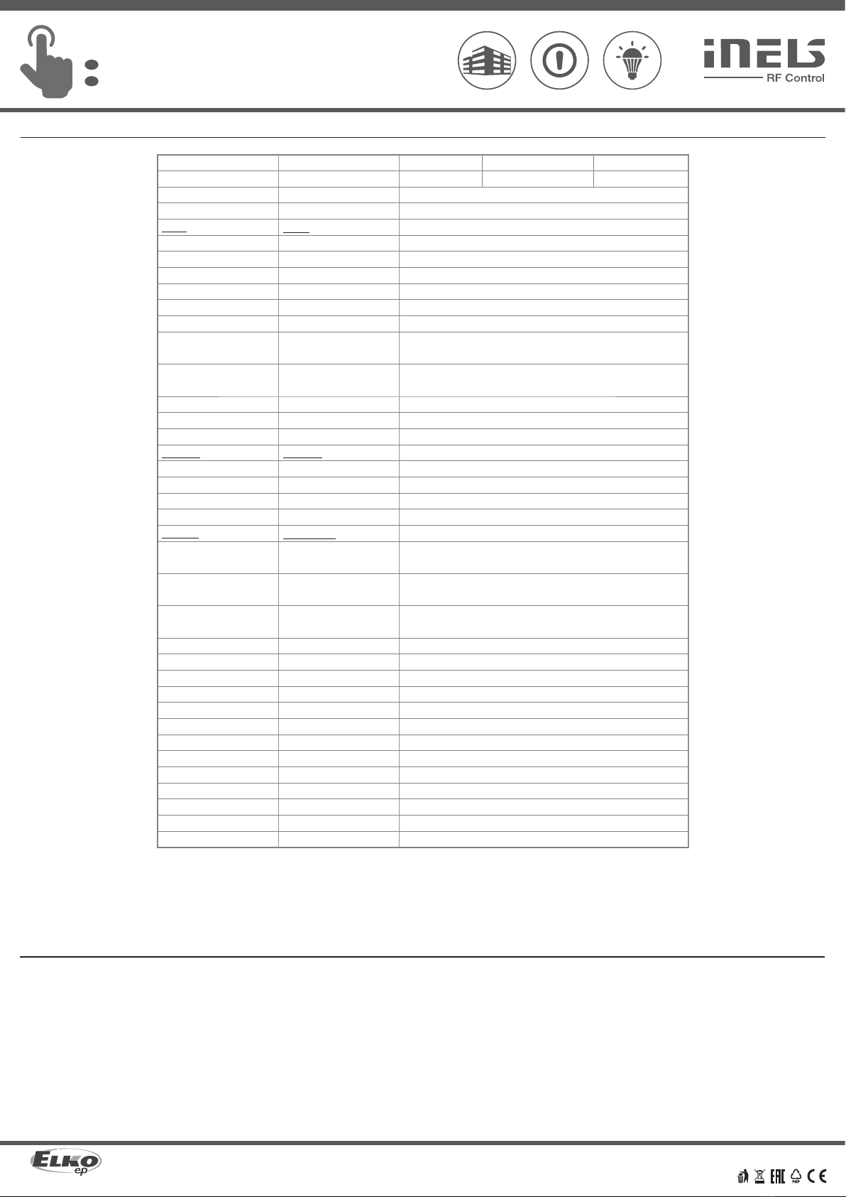
Technical parameters /
* Control button input is at the supply voltage potential.
Attention:
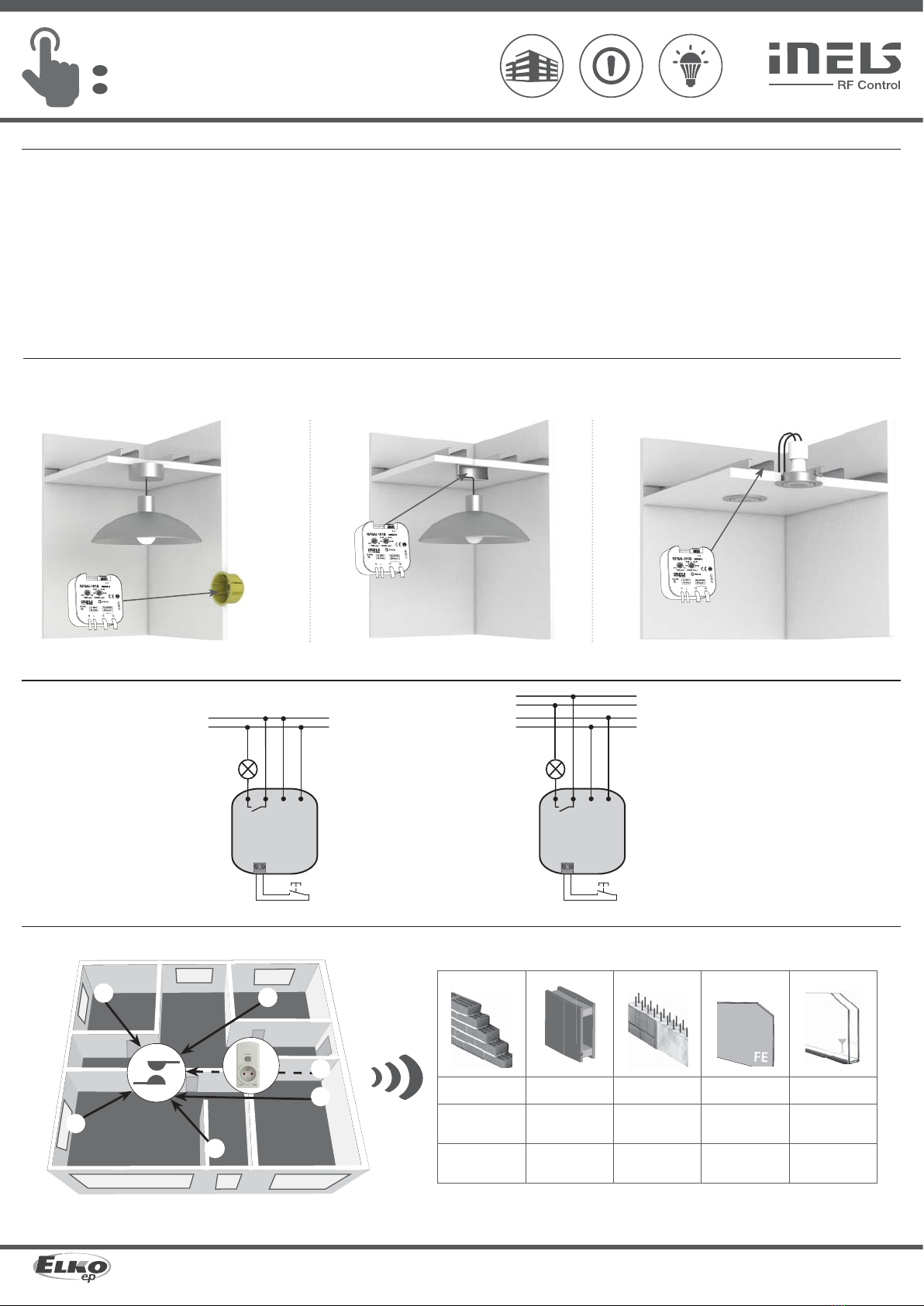
When you instal iNELS RF Control system, you have to keep minimal distance 1 cm between each units.
Between the individual commands must be an interval of at least 1s.
4 / 4
Instruction manual is designated for mounting and also for user of the device. It is always a part of its packing. Instal-
lation and connection can be carried out only by a person with adequate professional qualification upon under-
standing this instruction manual and functions of the device, and while observing all valid regulations. Trouble-free
function of the device also depends on transportation, storing and handling. In case you notice any sign of damage,
deformation, malfunction or missing part, do not install this device and return it to its seller. It is necessary to treat
this product and its parts as electronic waste after its lifetime is terminated. Before starting installation, make sure
that all wires, connected parts or terminals are de-energized. While mounting and servicing observe safety regula-
tions, norms, directives and professional, and export regulations for working with electrical devices. Do not touch
parts of the device that are energized – life threat. Due to transmissivity of RF signal, observe correct location of
RF components in a building where the installation is taking place. RF Control is designated only for mounting in
interiors. Devices are not designated for installation into exteriors and humid spaces. The must not be installed into
metal switchboards and into plastic switchboards with metal door – transmissivity of RF signal is then impossible.
RF Control is not recommended for pulleys etc. – radiofrequency signal can be shielded by an obstruction, inter-
fered, battery of can get flat etc. and thus disable remote control.
Warning
Supply voltage:
Apparent power:
Dissipated power:
Supply voltage tolerance:
Output
Number of contacts:
Rated current:
Switching power:
Peak current:
Switching voltage:
Min. switching power DC:
Insulation voltage between
relay outputs and internal circuits:
Isolates. voltage open relay
contact:
Mechanical service life:
Electrical service life (AC1):
Indication of relay switch:
Controlling
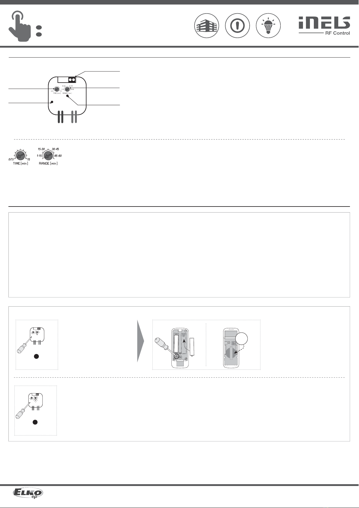
RF command from the detector:
Manual control:
External button:
Range in open space:
Other data
Open contact voltage external
switch:
Resistor for the management of
external switch:
Resist. of connection for open
contact:
Galvanic isolation of input:
Operating temperature:
Storage temperature:
Working position:
Mounting:
Protection:
Overvoltage category:
Contamination degree:
Terminals:
Terminals (CY wire, Cross-section):
Terminal length:
Dimensions:
Weight:
Automatyczne sterowanie oświetleniem
PL
* Wejście dla włącznika ma ten sam potencjał co napięcie zasilania.
Uwaga:
Podczas instalacji systemu iNELS RF Control koniecznym jest dotrzymanie minimalnej odległości
1 cm pomiędzy elementami.
Wymagany jest odstęp min. 1s pomiędzy kolejnymi poleceniami.
Instrukcja obsługi służy do celów montażu oraz dla użytkowników urządzeń. Instrukcja obsługi zawsze wchodzi w skład
opakowania urządzenia. Montaż oraz podłączenie mogą wykonywać wyłącznie osoby z odpowiednimi kwalifikacjami
zawodowymi, zgodnie z obowiązującymi przepisami, które w odpowiedni sposób zapoznały się z instrukcją obsługi
oraz działaniem urządzeń. Bezproblemowe działanie urządzeń jest również zależne od wcześniejszego sposobu
transportu, magazynowania oraz manipulacji. W przypadku wykrycia jakichkolwiek oznak uszkodzenia, odkształcenia,
awarii lub brakujących elementów, prosimy o nieinstalowanie urządzenia oraz zwrócenie się do sprzedawcy. Urządzenie
lub jego części muszą być potraktowane po końcu okresu używania jako odpad elektroniczny. Przed rozpoczęciem
instalacji należy upewnić się, że wszystkie przewody, podłączone części lub terminale nie są pod napięciem. W trakcie
montażu lub konserwacji koniecznym jest dotrzymanie przepisów bezpieczeństwa, norm, dyrektyw oraz przepisów
branżowych, dotyczących pracy z urządzeniami elektrycznymi. Nie należy dotykać części urządzeń pod napięciem
- ryzyko zagrożenia życia. Ze względu na właściwe przenikanie fal radiowych RF, pamiętaj o właściwym umieszczeniu
urządzeń w budynku, w którym są instalowane. Urządzenia RF Control są przeznaczone wyłącznie do montażu wewnątrz
budynków. Urządzenia nie mogą być instalowane na zewnątrz lub w pomieszczeniach wilgotnych, dalej nie mogą być
instalowane w metalowych szafach rozdzielczych lub plastikowych szafach rozdzielczych z metalowymi drzwiami -
uniemożliwi prawidłowe przenikanie fal radiowych. Urządzeń RF Control nie należy używać do sterowania urządzeniami
o podwyższonym ryzyku, takimi jak pompy, el. urządzenia grzewcze bez termostatu, windy, dźwigi, itp. - przepływ fal
radiowych może być przerwany, naruszony przez przeszkodę, bateria nadajnika może być rozładowana itp. Z wyżej
wymienionych powodów może dojść do zakłócenia lub uniemożliwienia sterowania.
Ostrzeżenie
230 V AC / 50-60 Hz 120 V AC / 60 Hz 12-24 V DC / AC 50-60 Hz
9 VA 9 VA -
0.7 W
+10 %; -15 %
1x switching / przełączny (AgSnO2)
12 A / AC1
3000 VA / AC1, 288 W / DC
30 A / max. 4s at / przy zmianie 10%
250 V AC1 / 24 V DC
100 mA / 10 V
basic insulation (Cat. III surges by EN 60664-1) /
izolacja podstawowa (kat. przep. III wg EN 60664-1)
1 kV
3x10⁷
5x10⁴
red / czerwona LED
866 MHz, 868 MHz, 916 MHz
button PROG / przycisk PROG (ON/OFF)
cable lenght max. 12 m / maks. długość przewodu: 12m*
up to / do 160 m
3 V
<1 kΩ
>10 kΩ
no / nie
-15 ... + 50 °C
-30 ... + 70 °C
any / dowolna
free at lead-in wires / luźne na przewodach doprowadzających
IP30
III.
2
0.5 - 1 mm2
2x 0.75 mm2 , 2x 2.5 mm2
90 mm
49 x 49 x 21 mm
50 g
Napięcie zasilania:
Moc pozorna:
Moc rozproszona:
Tolerancja napięcia zasilania:
Wyjście
Ilość styków:
Prąd znamionowy:
Moc włączana:
Prąd szczytowy:
Napięcie włączane:
Min. moc włączana DC:
Napięcieizolacyjne pomiędzy wyjściami
przekaźnikaoraz obwodami wewnętrznymi:
Napięcie izolacyjne rozwartego
styku przekaźnika:
Trwałość mechaniczna:
Trwałość elektryczna (AC1):
Sygnalizacja załączenia przekaźnika:
Sterowanie
Polecenie RF ze sterownika:
Sterowanie ręczne:
Przyciskiem zewnętrznym:
Zasięg w wolnej przestrzeni:
Pozostałe dane
Napięcie styku rozwartego
przełącznika zewn.:
Rezystancja przewodów prze-
łącznika zewnętrznego:
Opór przewodów przy
wyłączonym przycisku:
Izolacja galwaniczna wejścia:
Temperatura robocza:
Temperatura składowania:
Pozycja robocza:
Umocowanie:
Szczelność:
Kategoria przepięcia:
Stopień zanieczyszczenia:
Blok zacisków:
Zaciski (przewód CY, średnica):
Długość zacisków:
Wymiary:
Waga:
Dane techniczne

Other Elko Lighting Equipment manuals

Elko inels RFSAI-161B/230V User manual

Elko

Elko inels RFSAI-161B/230V User manual

Elko iNels RFDA-73M/RGB User manual

Elko

Elko iNels RFDA-73M/RGB User manual

Elko inels RFSAI-62B/230V User manual

Elko

Elko inels RFSAI-62B/230V User manual

Elko iNels RFDA-73M/RGB User manual

Elko

Elko iNels RFDA-73M/RGB User manual

Elko inels RFSAI-161B/230V User manual

Elko

Elko inels RFSAI-161B/230V User manual

Elko iNels RFDA-73M/RGB User manual

Elko

Elko iNels RFDA-73M/RGB User manual

Popular Lighting Equipment manuals by other brands

ProLights LEDCOMPASS8 user manual

ProLights

ProLights LEDCOMPASS8 user manual

GE StayBright HO HO HO Assembly manual

GE

GE StayBright HO HO HO Assembly manual

PLG PICTOR 5 user manual

PLG

PLG PICTOR 5 user manual

Vision & Control LDLF60x240-W5K7/UDC Instructions for use

Vision & Control

Vision & Control LDLF60x240-W5K7/UDC Instructions for use

MaxLite TRK WS Series operating instructions

MaxLite

MaxLite TRK WS Series operating instructions

Vega Industries PEl 6 Installation and instruction manual

Vega Industries

Vega Industries PEl 6 Installation and instruction manual

EuroLite LED FE-60 IR Flower Effect user manual

EuroLite

EuroLite LED FE-60 IR Flower Effect user manual

Inspire LEDFLEXI 2128KS-5-CCT-P instruction manual

Inspire

Inspire LEDFLEXI 2128KS-5-CCT-P instruction manual

LARSON EPL-MJ LED Series instruction manual

LARSON

LARSON EPL-MJ LED Series instruction manual

GE 75976 instructions

GE

GE 75976 instructions

Experia IRiS instruction manual

Experia

Experia IRiS instruction manual

NANLUX Dyno 650C manual

NANLUX

NANLUX Dyno 650C manual

Secom NOTTEC 30W Mounting instructions

Secom

Secom NOTTEC 30W Mounting instructions

LIGMAN JET 49 installation manual

LIGMAN

LIGMAN JET 49 installation manual

Elation Focus Spot 250R manual

Elation

Elation Focus Spot 250R manual

Future light PHB-300E Pro-Head-Beam user manual

Future light

Future light PHB-300E Pro-Head-Beam user manual

Integral LED ILEMPK010 installation instructions

Integral LED

Integral LED ILEMPK010 installation instructions

Varytec Street Bar IP65 16x3W TW user manual

Varytec

Varytec Street Bar IP65 16x3W TW user manual

manuals.online logo
manuals.online logoBrands
  • About & Mission
  • Contact us
  • Privacy Policy
  • Terms and Conditions

Copyright 2025 Manuals.Online. All Rights Reserved.