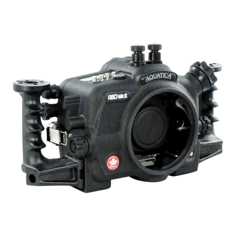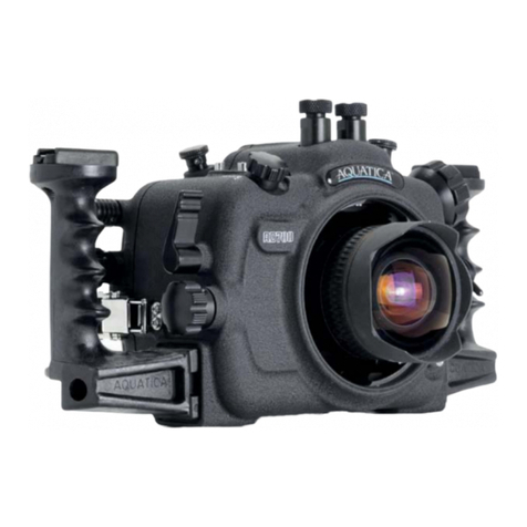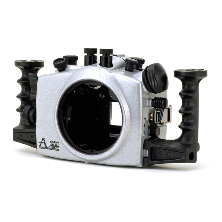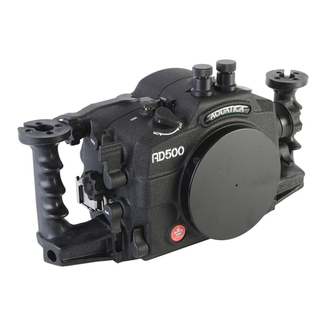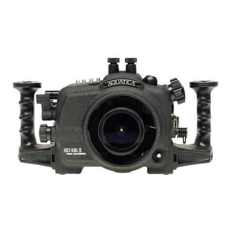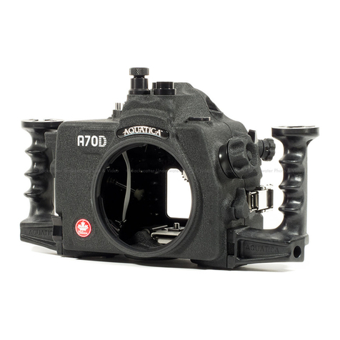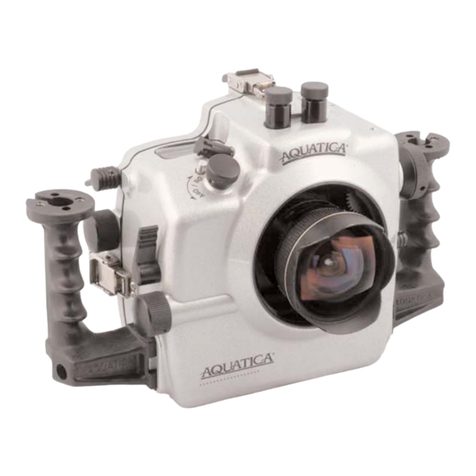
CONTROLS AND COMPONENTS IN DETAILS
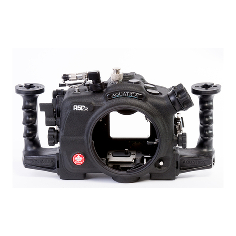
1. CAMERA QUICK RELEASE TRAY: This tray slide into the housing
to secures the camera into place.
2. CAMERA TRAY RELEASE TAB: Pressing on this tab will free the
quick release tray from the housing
3. CAMERA MOUNTING SCREW: Used to fasten the camera to the
Quick Release Tray
4. CAMERA ALIGNMENT POSTS: Two posts are provided to securely
keep the camera in alignment.
5. SHUTTER RELEASE LEVER: This extended lever provides
efcient access to the shutter release, always pull the shutter release
lever gently back, part way activates the camera meter and auto focus.
Pulling the lever back all the way triggers the camera. Note that
depending on the AF mode used, the camera lens may need to focus
properly before letting the camera trigger. Applying undue pressure on
the lever will not make the camera trigger faster and may only results
on damage to the camera shutter release.
6. MAIN DIALS ACCESS KNOB: Rotates clockwise and counter
clockwise. Use alone or in combination with other controls to select or
set various camera functions or modes. In “Manual” exposure mode,
this control the shutter speed settings (see camera manual).
7. HAND GRIPS (X2): Left and right grip allowing the mounting of
strobe arms and accessories.
8. GRIP’S ACCESSORIES MOUNTING HOLES: Two1/4-20 TPI
holes on each grip are ready to accept TLC Base Brackets or TLC
Base Ball for strobe arms or accessories.
9. M-Fn & AF AREA BUTTON: press to select either the focus point
or M-Fn.
10. ISO LEVER: Pull to engage the ISO value selector button rotate
either the Main Dial Knob (# 6) or the Quick Control Dial Knob (# 37).
11. TOP LCD PANEL WINDOW: Allows a clear view of the camera
top LCD panel.
12. EXPOSURE COMPENSATION BUTTON: Press to engage the
exposure compensation button, rotate the Quick Control Dial Knob
(#37) to sect the desired value.
13. WHITE BALANCE BUTTON: Press to engage the exposure
compensation button, rotate the Quick Control Dial Knob (#37) to select
the desired value.
14. LCD PANEL ILLUMINATION BUTTON: Press to illuminate the top
and rear LCD Panel
15. ACCESSORY BULKHEAD PLUG: This bulkhead connection allows
connecting various accessories to the housing; it has a ½ inch diameter
dimension.
16. RIGHT BULKHEAD CONNECTOR: Due to user preferences,
this bulkhead connector function may vary from housings to housing.
(see section on strobe connectors)
17. LEFT BULKHEAD CONNECTOR: Due to the user preferences, this
bulkhead connector function may vary from housings to housing.
(see section on strobe connectors)
18. BAYONNET MOUNTING FLANGE: allows the mounting of different
ports and extension rings on the housing.
19. PORT RELEASE LEVER: pull to release the locking mechanism
when removing a port or extension.
20. MOUNTING HOLE FOR ACCESSORY: a 1/4”-20 TPI hole is
supplied to accept a TLC accessory or TLC base ball for mounting a
strobe arm or a modeling light.
21. ACCESSORY BULKHEAD PLUG: This bulkhead connection allows
connecting various accessories to the housing; it has a ½ inch diameter
dimension.
22. FOCUS/ZOOM RELEASE DISC: A release disk is provided to
disengage the knob should you want to us a non AF-S lens in autofocus
or when you wish to remove the camera from the housing with lens
attached.
23. FOCUS/ZOOM KNOB: Turning allows manual focus of a single
focus lens or rotation of the zoom mechanism of a lens.
24. FOCUS/ZOOM PINION GEAR: Engages and operates the focus
or zoom gear attached to the lens.
25. LENS RELEASE KNOB: activates the lens release button on the
camera allowing easy removal of the lens.
26. LENS RELEASE KNOB LEVER: Applies pressure on the camera
lens lock button
27. ACCESSORY BULKHEAD PLUG: This bulkhead connection
allows connecting various accessories to the housing; it has a 16mm
diameter dimension.
28. SHOOTING MODE BUTTON: Press this button and rotate either
the Main Dial Knob (# 6) or the Quick Control Dial Knob (# 37) to
select the shooting mode.
29) AF-DRIVE BUTTON: Press this button and rotate the Main
Dial Knob (# 6) to select the AF Mode or the Quick Control Dial
Knob (# 37) to select the Drive mode.
30. METERING MODE & FLASH EXPOSURE COMPENSATION:
Press this button and rotate the Main Dial Knob (# 6) to select the
Metering Mode or the Quick Control Dial Knob (# 37) to select the
Flash Exposure Compensation
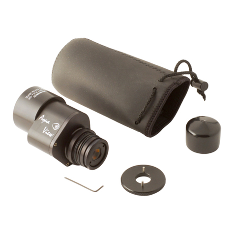
31. REMOVABLE VIEWFINDER: Afull view of the illuminated camera
viewnder displays all the necessary information. This viewnder
be can be removed and replaced with an optional enhanced Aqua
View Finder (straight or angled) for a larger displayed image.
Page 4
