Controls in detail, continued
17. MAIN BULKHEAD CONNECTOR: Two connectors are supplied as standard and are for connecting Nikonos type Sync Cord. This
is the main connector and can be ordered in 5 pins (for use with TTL converter) or 2 pins (default for manual strobe operation) and in
Ikelite versionn of 5 pins (for use with TTL converter) or 2 pins (for manual strobe operation).
18. SECONDARY BULKHEAD CONNECTOR: This connector is available in 2 pins for manual operation in a Nikonos type, it is dicon-
nectable and can be used in conjunction with the remote control # 19300 for remote triggering of the camera underwater.
19. AF-ON BUTTON: Press to activate auto focus, refer to camera manual for a description of the different options.
20. TOP LCD WINDOW: displays essential camera operating data.
21. AF / AE LOCK LEVER: Press down lever to engage auto focus or/and auto exposure, see camera manual for the different options
associated to this button.
22. LATCHES: Two heavy duty latches are provided with safety locks to protect against accidental opening.
23. FOCUS AREA / MULTI SELECTOR BUTTONS: These buttons have multiple uses. They allow the selection of the focus area, in
the menu mode, they are used to scroll up or down and left to right to choose from your menu selection and they are used in the delete
mode.
24. AUTOFOCUS MODE SELECTOR SWITCH: Rotate to select the desired focusing pattern of the camera.
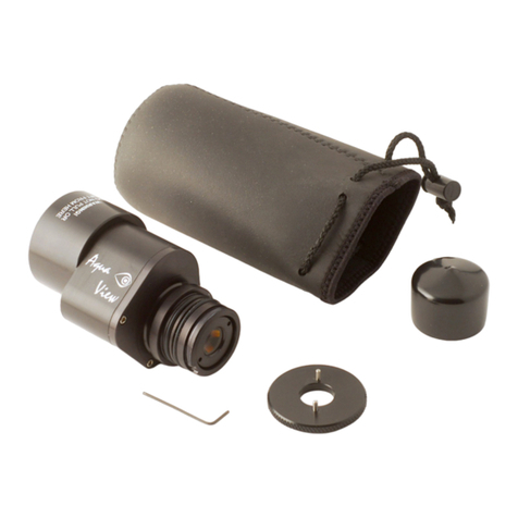
25. VIEWFINDER: A full view of the illuminated camera viewnder displays all necessary information. It is removable and can be replaced
with the Aqua View Finder # 20054 for enhanced viewing.
26. REAR VIEW DISPLAY WINDOW : allow viewing of menu and images
27. OK BUTTON : Press to acknowledge selected function.
28. PLAYBACK ZOOM IN BUTTON: Press to zoom in the image.
29. THUMBNAIL BUTTON: Press to zoom out and/or display images in “contact sheets” of 4 or 9 images.
30. PROTECT BUTTON: Press to protect selected image from accidental deletion.
31. MENU BUTTON: Press to activate menu, use multi selectors buttons (21) to navigate, press enter button (25) to choose a selec-
tion.
32. DELETE BUTTON: Press to delete images, use multiple selector buttons to select and press the enter button to delete. Used in con-
junction with mode selector button (14) to format the card inside the camera
33. PLAYBACK BUTTON: Press to activate the monitor and review images.
34. RELEASE MODE SELECTOR WINDOW: Allows viewing of the different selector options.
35. FOCUS MODE SELECTOR LEVER: Rotate to select between manual, single or continuous focusing. SELECTOR LEVER FORK:
Must be in M (manual) position when sliding camera in the housing, once installed, desired focus mode can be selected.
36. LENS RELEASE LEVER: activates the lens release button on the camera allowing easy removal of the lens.
37. RUBBER PADS: Those four pads are supplied to prevent your housing from skidding on wet surface
38. SACRIFICIAL ANODES: (3X) zinc anodes are installed to protect your housing against salt water corrosion; theses are made to de-
teriorate easier than the other strategic part of your housing, hence the name sacricial anodes. These anodes will need to be replaced
as needed.
39. MOUNTING HOLES: Two 1/4” X 20 holes are provided for mounting strobes trays or accessories.

