7. When using large dome port such as the 6”, 8” and 9.25”
with an extension, uses of the optional extension ring to
port locking collar (# 18469) is recommended, this add
another layer of safety by preventing the larger dome port
from rotating during manipulation or transportation to the
dive site.
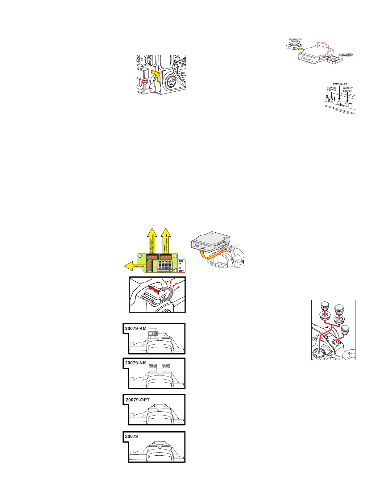
To remove a port or extension from the bay-
onet, press the port release lever (#22) and
rotate the port or extension counter clockwise,
carefully pull the port or extension off the bayonet.
Note: It is recommended that you familiarize yourself with this
procedure by trying it without the camera in or the back cover
attached to the housing; this to better visualize the internal functioning
of the bayonet and port.
CONNECTING LIGHTING EQUIPMENT
Mounting the strobe arms will require that the necessary shoes,
brackets or Base Ball be attached to the threaded holes located on the
top of the hand grips (# 25). Use of the Aquatica Delta 3 Strobe Arm
System is recommended.
Three 1/4”-20 threaded holes on the bottom (# 50) of this housing
can be used for various mounting applications. A similar sized 1/4”-
20 hole with thread is located on top of the housing (# 15), and is
ready to accept a 1”/25mm Technical Lighting Control Delta 3 (#
77651) for adapting a small dive light or an additional strobe arm
can be attached using a clamp.
Strobe illumination setup: Using wired connections
Sony Digital cameras housing with wired
connection are setup for manual exposure
with either two individual Nikonos (# 20079-NK)
or one Ikelite type connectors (# 20079-KM).
These connectors are part of a modular sys-
tem whit an internal switchboard.
Set up instruction: All switches must be in
the OFF (lower) position on the switch-
board so that only the ground and sync
are left active. This will allow two under
water strobes or housed ashes to be
connected directly via the main and sec-
ondary bulkhead or with a dual sync cord
of the main connector.
Note on sync cords maintenance:
When preparing the sync cord, be
sure to lubricate the O-ring on the
sync cord’s connector with a light
coat of the strobe manufacturer origi-
nal O-ring lubricant, also advisable is
to put a light coat of O-ring lubricant
on the threads of this connector to
help prevent threads from freezing up.
Some electrical sync cord are known to
use dissimilar metal in their construc-
tion, these can create an unwanted
electrolytic reaction. Whenever us-
ing sync cord with metal tting, it is
recommended that they be removed,
cleaned and the threads lubricated on
a daily basis.
For user of the 20079-OPT version: Start by selecting the desired optical
cord adapter(s) if needed, and insert in the optical port base(s).
The LED ash trigger included with
the 20079-OPT version operates on
two standard CR2450 batteries. To
install these, pull out the batteries holders,
insert them in their respective holder with the positive side (+) facing up,
and push back the batteries holders into place when done.
There are two switches and a status LED on the
back of the trigger unit, the one located on the left
side is the power switch, slide it to the on (I) position,
the two LED located on top of the trigger should
blink once and the status LED should blink green informing
you that the unit is ready for operate. In the event that the battery
power would be low, this status LED will blink red, you should then
proceed to replace both batteries with fresh ones.
The switch located on the right side is the power ratio selector
switch, while most strobes will operates properly in the low power
position, some strobes, such as the newer Sea & Sea YS-D2, requires
a stronger light output in order to sync, in such case simply move
the power ratio switch to the upper position, this will increase the
output power of the LED’s. It is important at this point, to note that
in order to have consistent performances, a premium quality optical
ber cord that will carry the light signal from the trigger adequately
is recommended. Some lesser quality optical bers do have poor
light transmitting capabilities, and if possible, you should avoid using
them in the sake of reliability.
Mount the LED ash trigger on the camera
hot shoe, push until it stop, switch unit on
and trigger the camera a few times, should
the status light turn red, replace batteries
before proceeding with the dive. The trigger
unit itself has insignicant battery drain and
these last quite a long time, on the other
hand, you should preferably power down the camera and the un-
derwater strobe(s) in order to avoid unnecessary battery drainage
on them while transiting to the dive site.
ADAPTABLE BULKHEAD CONNECTION
This housing features an adaptable bulkhead
access hole, the housing is shipped with the
16mm diameter adapter installed by default.
This being a popular size for mounting exter-
nal monitors. Should you wish to add other
accessories, the 0.50” version might be better
adapted to that purpose, to swap adapter, sim-
ply follow this procedure:
Remove the adapter retaining O-ring from the inside and push the
adapter out, On the one to be installed, inspect and lubricate the
sealing O-ring and push the new adapter in place and install the
retaining O-ring back on the inside..
As is customary with any O-ring replacement, it is always suggest-
ed to validate the sealing integrity by performing a pressure test, an
immersion of the housing without camera inside, or if a Surveyor
Vacuum system is installed, to test by extracting the pressure and
monitoring the vacuum for any sign of leakage.
IMPORTANT NOTICE: Installation of any accessories on your housing
should be only be attempted by Aquatica or by qualied technicians
from an authorized Aquatica Service Center.
Page # 08