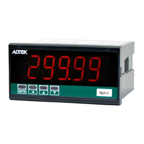
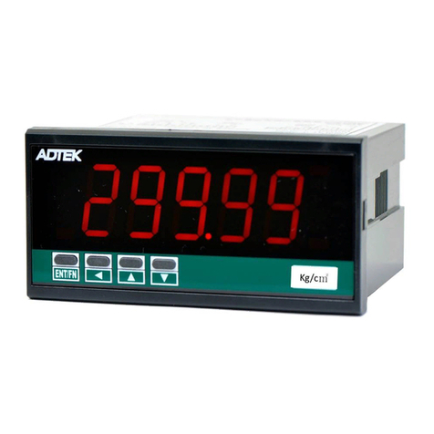
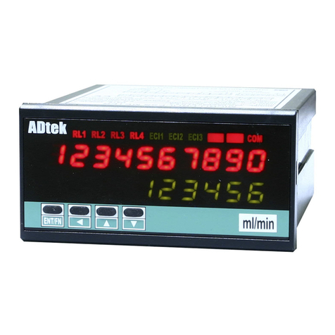
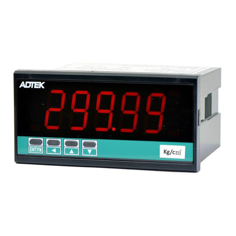
ADTEK CM1 Series User manual

CM1-SERIES
434d31534552494553-4d-454e-43-41, Rev 1.3
2018-07-02
11
*434d31534552494553-4d-454e-43-41*
1 /28
CM1
Programmable Meter
User Manual
■DESCRIPTIONS
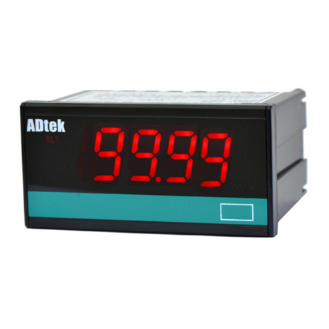
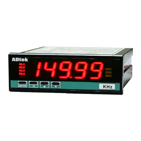
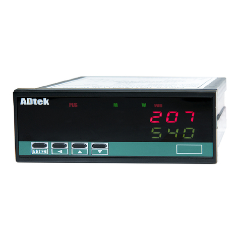
CM1 series Indicator has been designed in simple function and 4 digital 20.0mm LED displays
with economic cost.
They are can be programmed by tack switches that are hidden in backside of front bezel.
They are also available 1 option of 2 Relay outputs, 1 Analogue output or 1 RS485(Modbus RTU Mode)
interface with versatile functions such as control, alarm, re-transmission or communication for a wide range
of industrial applications.
■FEATURE
Common Function
●Optional output available for one of 2 relay, analogue or RS485
●Operation key built (in the front panel), can be set to display
range;terminal straight into the design, no poor
contact questions;installation depth of only 72mm
【CM1-VA ECNOMIC VOLT/CURRENT Meter】
●Measuring AC / DC Voltage 0~50.00mV/~600.0V / Current 0~1.999mA/~10.00A
【CM1-PR 4 Digital DC Process Meter】
●Measuring DC voltage 0(1)~5V/~10V OR DC current 0(4)~20 mA/0~10 mA
●Purchasing power to stimulate additional DC24V, 30mA
【CM1-TR RTD Temperature Meter】
Measuring RTD type : Pt100Ω/ Pt1000Ω
Unit can be set to ℃or ℉
【CM1-RL 5 Digital RPM/Line speed Meter】
●Measuring Frequency input 1Hz~6KHz,Do not need to specify the frequency
range;Input Model(NPN、PNP、….) and Pulse level can be switch by DIP
●Optional excitation power DC12V, 30mA
【CM1-F 5 Digital Frequency Meter】
●Measuring Frequency input 1Hz~6KHz sine wave
■APPLICATIONS
●CM1-VA High and low voltage power disk / motor control panel - Overload /mechanical voltage and
current display / test equipment voltage / current display, alarm protection and computer connections.
●CM1-PR Process in a variety of sensors (pressure transmitters, temperature and humidity transmitter ...) to do live
shows,and computer alert to protect the connection.
●CM1-TR With RTD (Pt100Ω/ Pt1000Ω) sensor for temperature display and control. Process alarm or communication
for data collection.
●CM1-RL Mechanical speed of the motor / speed limit on-sitedisplay, alarm protection and computer connections.
●CM1-F Sine wave Frequency Measuring, Alarm or Communication with PC/PLC.

CM1-SERIES
2 / 28
Rev 1.3
2018-07-02
■INSTALLATION
Please check the specification, wire diagrams and functions on the label of the meter before
installation..
DIMENSIONS & Panel Cut Out
■INSTALLATION
96.0
48.0
92.0+0.2
44.0+0.2
Panel Cut out
Front View
Unit: mm
7.0
13.0
60.0
PANEL CUT-OUT:
92+0.2(W) x 44+0.2(H) mm
Kg/cn
FIX HOLDER:
63 mm(L) / W M3
1.0~7.0mm
Wiring Diagram
Please check the voltage of power supplied first, and
then connect to the specified terminals. It is recommended
that power supplied to the meter be protected by a fuse or
circuit breaker.
Remark
,
PT can not short in secondary
;
CT can not
open in secondary
Wiring may be changed, follow the wiring diagram on
theinstrument wiring
Terminals
20A/300Vac, M3.5, 22~14AWG;
Max torque: 12kg-cm
(If the use of electric driver, please adjust the torque electric driver)
7.0mm max
7.0mm max
Input
Signal
Terminals:
20A/300Vac, M3.5, 0.5~2.0mm2 (22~14AWG)
AUX.Power
7
8
5
6
4
3
2
1
AC230V
AC115V
15
16
13
14
12
11
10
9
Option output
terminal
Power&Input
Terminals
+
-
If power supply noise interference, install an isolation transformer.。
Power Supply
AC115/230V
Filter or Transformer
L
N
G
L
N
G
1A Fuse
4
5
7
8
6

CM1-SERIES
3 / 28
Rev 1.3
2018-07-02
CM1-F Input Connection
11
12
14
15
13
16
Signal Input
Sine wave frequency
Input Signal Connection
CM1-VA Input Connection
3
1
2
MAX. Input:
600V or 10A
Remark:
PT can not short in secondary;
CT can not open in secondary
Current Shunt
CT
CM1-PR Input Connection
2-wire sensor transmitter
connection 4(0)~20mA Input Connection
1
2
4
5
3
24Vdc
EXCIT.Power
4~20mA
Input
1
2
4
5
3
24Vdc
EXCIT.Power
4~20mA
Input
4~20mA
3-wire sensor transmitter
connection 0~10V Input Connection
1
2
4
5
3
24Vdc
EXCIT.Power
0~10V
Input
+V
Vo
0V
1
2
4
5
3
24Vdc
EXCIT.Power
0~10V
Input
0~10V
CM1-TR Input Connection
Terminal blocks:
20A/300Vac, M3.5, 0.5~2.0mm2 (22~14AWG)
AUX.POWER
7
8
5
6
4
3
2
1
Power & Input
terminal block
b
B
A
RTD
115V
230V
CM1-RL Input Connection
DIP D-S
1
2
3
4
5
NPN
ON
PNP
ON
CONTACT
ON
ON
Voltage pulse 5VP
Voltage pulse 12VP
ON
Voltage pulse 24VP
ON
DIP switch position cut to the bottom, behalf the DIP switch is ON
1
2
3
+Vdc
Out
0V
+IN
0V
+V
DIP switch to switch the input mode and pulse level but must
beconsistent with the input signal
OUTPUT
(One output available of Relay,Analogue or RS485)
Relay output
15
16
13
14
12
11
10
9
RELAY 2
b
c
a
NC
NO
RELAY 1
b
c
a
NC
NO
Analogue Output
12
11
10
9
RS485 port
Max. Distance: 1200M
Terminate Resistor
(at latest unit):
120~300ohm/0.25W
(typical: 150ohm)
A
B
9
12
11
10

CM1-SERIES
4 / 28
Rev 1.3
2018-07-02
■OPERATING
■FRONT PANEL
~A
Engineer Unit
Display
screen
R L 1
COM
RL2
Relay status
indication
Communication
status indication
Number screen:
●
: red high-brightness LED.
Output LED:
●Relay Energized: 2 square red LED
RL1
display when Relay 1 energized
RL2
display when Relay 2 energized;;
COM
RS485 Communication:1 square orange LED;
COM
will
flash when the meter is receive or send data, and
COM
flash
quickly means the data transient quicker.。
Stickers:Each instrument will be attached to the
relay function are engineering
units stickers and stickers; Please choose according
to site usage label affixed to the front panel functions
and units。
●Stickers:
H i
Hi Action
L o
Lo Action
●
Hi. H
Hi Action &Hold
Lo. H
Lo Action &Hold
●Unit stickers: 106 kinds
Operating Key: 4 keys for
Enter(Function) /
Shift(Escape) /
Up key /
Down key
Pass Code:
4-digit password to set; To enter the parameter screen,
you must enter the correct
password, please remember the password. If youforget
the password, please contact the company. This
password can be in steps [Pcode] to change
■OPERATING KEY:
*Please access to the Programming Level tocheck and set the parameters when users start to run the meter
Operating Key: 4 keys for
Enter(Function) /
Shift(Escape) /
Up key /
Down key
The meter has designed operation similar as PC's
and
Enter
. In any page, press
key means "enter" or "confirm setting", and
press
key means "escape(
Esc
)" or "shift".
In Programming Level, the screen will return to Measuring Page after do not press any key over 2 minutes, or press
for 1 second.
Function Index
Setting Status
(=
)
Enter/Fun key
(1) In any page, press
to access the level or function index
(2) From the function index to access setting status
(3) Setting Confirmed, save to EEProm and go to next
function index
(=
)
Shift key
(1) In measuring page, press
for 1 second to access user level.
(2) In function index, press
for 1 second to go back upper level.
(3) In function group index, press
for 1 second to go back
measuring page
(4) In setting status, press
to Shift the setting position.
(5) In setting status, press
for 1 second to abort setting
and go back this function index.
(=
)
Up key
(1) In function index, press
to go back to previous function index
(2) In setting status for function, press
to select function
(3) During number Setting, press
can roll the digit up
(=
)
Down key
(1) In Function Index Page, press
will go to the next Function
Index Page.
(2) In setting status for function, press
to select
function
(3) During number Setting, press
can roll the digit
down.

CM1-SERIES
5 / 28
Rev 1.3
2018-07-02
OPERATING DIAGRAM (The detail description of operation, please refer to operating manual.)
Power ON
88888
Self-diagnosis
cm!va
Show the model number
cm!va: Voltage and current
cm!pr: 0~10V/4~20mA
cm1-tr: Pt100Ω/Pt1000Ω
cm!rl: Speed / line speed
cm1-f: Frequency
ver!0
Show the firmware version
9999
MEASURING PAGE
1Sec
Access User Leve
1Sec
Escape User Leve
Pcode
enter
Enter the password
to access programming
Level
Pass Code
Default:1000
input
group
Into A
[Input group], the
related parameter
1Sec
relay
group
Into B
[relay functional
groups], the
related parameter
1Sec
ao
group
lnto D
[analog output gr
oup], the
related parameter
1Sec
rs485
group
Into E
[RS485 functional
groups], the
related parameter
1Sec
NO

CM1-SERIES
6 / 28
Rev 1.3
2018-07-02
0. User Level
9999
1Sec
0-01
min
0-02
max
0-03
Mrst
MEASURING
PAGE
Minimum
value of PV
saving
Maximum
value of
PV saving
Reset the saved
value of
Maximum &
Minimum
0-04
ry!sp
Relay1
Set-point
1Sec
0-07
cm!va
0-06
rYrst
0-05
ry@sp
model of the meter
firmware version
Checking only
Reset for
energized
Latch of
Relay
Relay 2
Set-point
Programming Level
A. INPUT GROUP
【CM1-VA/CM1-PR/CM1-TR】
input
A-01
pVdp
A-02
lOsc
A-03
hIsc
Decimal
Point of PV
Low scale
of PV
High scale of
PV
Note:If the model is
CM1-TR, the Lo.Sc(A-02)
and Hi.Sc(A-03) are fixed.
Fine Low point Adjustment for PV
display
A-04
pVzro
Fine high point Adjustment for PV
display
A-05
pVspn
Clear Fine Zero / Span Adjustment
for PV display
A-06
ZSclr
Low Cut the
PV
A-07
lOcut
Average
update for
PV
A-08
avg
1Sec
C
A-11
Pcode
A-10
Dfilt
A-09
Mavg
Pass Code setting for
access to Programming
Level
Digital filter
Moving
Average
update for PV
【CM1-RL/CM1-F】
input
A-01
pVtyp
A-02-1
ppr
A-02-2
Eunit
Select Display
type line
speed / rpm/
Frequency
Input pulse
ratio setting;
Line Speed
display units
select
Note:If display type
select frequency, A-02-x
items will not appear
A-02-3
diamt
Shaft
Diameter
set
A-03
dp
Display
decimal
point
position
select
1Sec
A-10
Pcode
Pass Code setting
for access to
Programming
Level
A-04
factr
Ratio Factor
A-09
Dfilt
Digital filter
A-05
lOcut
Display low
cut
A-08
avg
Average update
for PV
A-06
itOmd
Display set
to zero
A-07
ito
Display zero
time setting

CM1-SERIES
7 / 28
Rev 1.3
2018-07-02
D.ANALOGUE OUTPUT GROUP
ao
D-01
aOtyp
D-02
aOls
D-03
aOhs
Analogue
Output type
selection
low point is
relative to the
lowest of
Analogue
output
high point is
relative to the
highest of
Analogue
output
D-04
aOzro
Fine Zero
Adjustment
for
Analogue
Low
Output
1Sec
D-07
aOlmt
D-06
ZSclr
D-05
aOspn
Analogue
Output High
Limit
(CM1-RL/CM1-F
No this Fun.)
clear fine
Zero / Span
Adjustment
for Analogue
output
Fine Span
Adjustment
for Analogue
High Output
E. RS485 GROUP
rs485
E-01
adres
E-02
baud
E-03
prity
Device
number of the
meter
Baud rate
Parity
1Sec
B. RELAY GROUP
relay
B-01
rYsb
B-02
rYsd
B-03
ry!md
Start band
for Relay
energized
Start delay
time for
Relay
energized
Relay 1
energized
mode
B-04
ry!hy
Relay 1
Hysteresis
B-05
ry!rd
Relay 1
energized
delay time
B-06
ry!fd
Relay 1
de-energized
delay time
1Sec
B-10
ry@fd
Relay 2
de-energized delay
time
B-07
ry@md
Relay 2
energized
mode
B-09
ry@rd
B-08
ry@hy
Relay 2
energized
delay time
Relay 2
Hysteresis
F. INIT GROUP
init
F-01
init
Initialization
set:7170
1秒

CM1-SERIES
8 / 28
Rev 1.3
2018-07-02
OPERATING DIAGRAM (Into the User Level)
9999
1Sec
0-01
min
0-02
max
0-03
Mrst
MEASURING
PAGE
Minimum value
of PV saving
Maximum value
of PV saving
Reset the saved
value of Maximum
& Minimum
0-04
ry!sp
Relay1 Set-point
1Sec
0-07
cm!va
0-06
rYrst
0-05
ry@sp
model of the meter
firmware version
Reset for
energized Latch of
Relay
Relay 2 Set-point
INDEX
Step
FUNCTION DESCRIPTION
PARAMETERS & SETTING
SET
POWER ON
Please check the specification
and wiring diagrams firstly.
*****
Self-diagnosis
(LED All bright)
cm!va
Model
cm!va: Voltage / Current
cm!pr: DC 0~10V / 0~20mA
cm1-tr: Pt100Ω/ Pt1000Ω
cm!rl: RPM / Line speed
cm1-f: Frequency
ver!0
Firmware version
9999
Measuring Page
Press
for 1 second return to Measuring Page
0−01
min
)0
min (PV Minimum storage): the Minimum
value of PV saving
When the meter power is turned on, both began to record
shows that the minimum value had occurred;
Except by [Mrst] (step 0-03) to perform cleanup functions
or instrument off; otherwise been recorded
and stored automatically update the new value.
Checking only
0−02
max
99(9
max (PV Maximum storage): the Maximum
value of PV saving
When the meter power is turned on, both began torecord
shows
that the maximum value has occurred;Except through [Mrst]
(step 0-03) to perform cleanup functions
or instrument off; otherwise will always be
recorded and stored the new value is automatically updated
Checking only
0−03
Mrst
no
no
yes
Mrst (Maximum & Minimum reset): Reset
the saved value of Maximum & Minimum
Be stored maximum / minimum values, this functioncan
be removed. This meter will be removed immediately after
the relatively new storage maximum/ minimum values。
Setting Range: yes / no
yes(Yes): Clear the
stored maximum /minimum
value
no(No): Does not clear the
storedmaximum / minimum
values
&
Cycle selection
Determine

CM1-SERIES
9 / 28
Rev 1.3
2018-07-02
0−04
ry!sp
10)0
10)0
10)9
99(9
ry!sp (Set-point of relay 1): Relay 1
Set-point
Setting Range: -1999~9999
(CM1-RL/CM1-F:-19999~99999)
Shift
Up
Down
Enter
0−05
ry@sp
10)0
10)0
10)9
99(9
ry@sp (Set-point of relay 2): Relay 2
Set-point
Setting Range: -1999~9999
(CM1-RL/CM1-F:-19999~99999)
Shift
Up
Down
Enter
0−06
rYrst
no
no
yes
rYrst (Reset relay hold): Reset for
energized Latch of Relay
Setting Range: NO/YES
Shift
Up
Down
Enter
0−07
cm!va
ver!0
cm!va:model of the meter firmware version
cm!va(CM1-VA):Voltage / Current
cm!pr(CM1-PR): DC 0~10V / 0~20Ma
CM1-TR(CM1-TR): Pt100Ω/ Pt1000Ω
cm!rl(CM1-RL): RPM / line speed
cm1-f(CM1-F): Frequency
ver!0(Ver 1.0):firmware version
Checking only;The model
number and software version will differ
according to different models
0−01
min
)0
Cyclic to first page
Under the screen in any of the above
Press
for 1 sec. back to
Measuring
Into the Programming Level
INDEX
Step
FUNCTION DESCRIPTION
PARAMETERS & SETTING
SET
99(9
Measuring display
enter
Pcode
Default:1000
0000
0000
1000
Pass code screen
To change the password set to
Step A-11, and do not forget
the password
Pass Code
Pass code input
Press
Into
Programming Level
YES
Press
1 Sec Can back to Measuring display
theMeasuring display

CM1-SERIES
10 / 28
Rev 1.3
2018-07-02
Input parameter group
CM1-VA/CM1-PR/CM1-TR
input
A-01
pVdp
A-02
lOsc
A-03
hIsc
Decimal Point of
PV
Low scale of PV
High scale of PV
A-04
pVzro
Fine Low point Adjustment
for PV display
Note: If the model is CM1-TR, the
Lo.Sc(A-02) and Hi.Sc(A-03) are fixed.
A-05
pVspn
Fine high point Adjustment
for PV display
A-06
ZSclr
Clear Fine Zero / Span
Adjustment for PV display
A-07
lOcut
Low Cut the PV
A-08
avg
Average update
for PV
1Sec
A-11
Pcode
A-10
Dfilt
A-09
Mavg
Pass Code setting for
access to Programming
Level
Digital filter
Moving Average
update for PV
INDEX
Step
FUNCTION DESCRIPTION
PARAMETERS & SETTING
SET
Pass Code
Pass code input
input
group
Input function group promptscreen
Any of the following screen Press
1sec,back Input group
A−1
pVdp
0
0
00)0
pVdp(Decimal Point of PV): Decimal
Point of PV
Setting Range:
0/ )0 / )00 / )000
&
Cycle selection
Enter
A−2
lOsc
)0
00)0
••••
00)0
00)0
lOsc(Low scale): Low scale of PV
Note: If the model is CM1-TR, the Lo.Sc(A-02) and
Hi.Sc(A-03) are fixed.
Setting Range: -1999~9999
(CM1-RL/CM1-F:-19999~99999)
Shift
Up
Down
Enter
SCALE
Default: [lOsc]: )00, [hIsc]: 5)00
Changed: [lOsc]: 2%00, [hIsc]: 9(99
Negative Slope
9(99
[hIsc]
)00
[lOsc]
5)00
[hIsc]
2%00
[lOsc]
%
)00
%
10)00
%
5)00
INPUT
YES

CM1-SERIES
11 / 28
Rev 1.3
2018-07-02
A−3
hIsc
99(9
99(9
99(0
••••
90)0
20)0
hIsc(High scale): High scale of PV
Note: If the model is CM1-TR, the Lo.Sc(A-02) and
Hi.Sc(A-03) are fixed.
Setting Range: -1999~9999
(CM1-RL/CM1-F:-19999~99999)
Shift
Up
Down
Enter
A−4
pVzro
)0
00)0
••••
00)0
00)0
pVzro: Fine Zero Adjustment for
PV display
For Zero & Span of PV, users can get the
"Fine Adjustment" by front key. It's an easy
way to “Just Key-In” the value that the user
wants to show in the current input signal.
設定範圍: -1999~9999
Shift
Up
Down
Enter
A−5
pVspn
)0
00)0
••••
00)0
00)0
pVspn:Fine Span Adjustment for
PV display
It's same function as like as [pVzro].
Setting Range: -1999~9999
Shift
Up
Down
Enter
A−6
ZSclr
none
none
both
ZSclr: Clear Fine Zero & Span
Adjustment for PV display
Setting Range:
none(None): Do not clear the fine
adjustment of Low / High.
pV.zro(PV.Zro): To clear the fine
adjustment Low.
pV.spn (PV.SPn): To clear the fine
adjustment High
both(Both): To clear the fine
adjustment of Low and High
&
Cycle selection
Enter
A−7
lOcut
)0
00)0
00)0
00!0
lOcut (Low Cut): Low Cut the PV
Low Cut set to be +0.50
Low Cut is set for 0.50, if the PV is
from -0.50~+0.50, that display will be 0.
PV according
to input signal
Present
Value
Low cut
function
0.50
-0.50
)50
[lOcut]
X1
X1
Setting Range: -1999~9999 counts
Shift
Up
Down
Enter
Low Cut set to be -0.10
-0.10
Low cut
function
Low Cut is set for -0.10, if the PV is
under (< = -0.10), that display will be -0.10.
Present
Value
PV according
to input signal
-)10
[lOcut]
X2

CM1-SERIES
12 / 28
Rev 1.3
2018-07-02
A−8
avg
5
5
09
09
99
avg (Average): Average update for PV
The meter’s sampling is 15cycle/sec
If the [ avg](Average) set to be 3 to
express the display update with 5 times/sec.
The meter will calculate the sampling 1-3
and update the display value. At meantime,
the sampling 4-6 will be processed to
calculate.
Setting Range: 1(NONE)~99 times
Shift
Up
Down
Enter
A−9
Mavg
8
8
09
09
99
Mavg (Moving Average):Moving Average
update for PV
In the first updated display value will be
same as average function. In the next
updated display value, the function will get
the new fourth sample (sample 4) then
throw away the first sample (sample 1) that
the newest 3 samples(sample 2,3,4) will be
calculated for the updated display value.
Setting Range: 1(NONE)~99 times
Shift
Up
Down
Enter
A−10
Dfilt
8
08
09
09
99
Dfilt (Digital filter): Digital filter
The digital filter can reduce the influence
of spark noise by magnetic of coil.
If the values of samples are over digital
filter band(fixed in firmware and about 5% of
stable reading) 3 times (Digital Filter set to
be 3) continuously, the meter will admit the
samples and update the new reading.
Otherwise, it will be as treat as a noise and
skip the samples.
Setting Range: 1(NONE)~99 times
Shift
Up
Down
Enter
A−11
Pcode
0000
1000
1009
••••
1999
9999
Pcode (Pass Code): Pass Code setting
for access to programming level
Please remind and write down the new pass
code so that access to programming level.
Setting Range: 0000~9999
Shift
Up
Down
Enter

CM1-SERIES
13 / 28
Rev 1.3
2018-07-02
CM1-RL/CM1-F
input
A-01
pVtyp
A-02-1
ppr
A-02-2
Eunit
DisplayType
Line
speed/RPM
Selection
Input Pulse
precedes set;
Line Speed
Display units
selection
A-02-3
diamt
Shaft diameter
set
A-03
dp
Decimal Point
set
A-04
factr
Ratio Factor of
PV
1秒
A-10
Pcode
Pass Code setting
foraccess to
programming level
A-05
lOcut
Low Cut the PV
A-09
Dfilt
Digital filter
A-06
itOmd
Zero mode
setting
A-08
avg
A-07
ito
Average update
for PV
Zero tine
setting
INDEX
Step
FUNCTION DESCRIPTION
PARAMETERS & SETTING
SET
Pass Code
Pass code input
input
group
Input function group promptscreen
Any of the following screen Press
1sec,back Input group
A−1
pVtyp
lNspd
lNspd
rpm
pVtyp (PV type selection):
DisplayType Line speed/RPM Selection
The meter has a measurement line speed,
RPM and frequency functions.
Users can simply set the display purposes,
the meter will start the function of the
corresponding。
Setting Range:
lNspdLinearly Line Speed:;
rpmRPM:
Revolution(s) Per Minute
rps(RPS):
Revolution(s) Per Seconds
hz(Hz): Frequency
khz(kHz): Frequency
&
Cycle selection
Enter r
A−2−1
ppr
1
1
99999
pVtyp selected ( rpm / rps) /
(lNspd),the fun. will display
ppr(Pulse/rotation): Input Pulse
precedes set
Setting Range: 1~99999
Shift
Up
Down
Enter
YES

CM1-SERIES
14 / 28
Rev 1.3
2018-07-02
A−2−2
Eunit
m/mn
m/mn
yd/mn
pVtyp selected (lNspd),the fun.
will display
Eunit(Engineer Unit):
Line speed display unit selection
Setting Range:
m/mn: (M/min)
cm/mn: (CM/min)
yd/mn: (Yd/min)
ft/mn: (Ft/min)
&
Cycle selection
Enter
A−2−3
diamt
)1000
)1000
(9999
pVtyp selected (lNspd) ,the fun.
will display
diamt(Diemeter):
Shaft diameter set
Setting Range:
0.0001~9.9999M(公尺)
Shift
Up
Down
Enter
A−3
pVdp
0
0
)0000
pVdp:Decimal Point of PV;
There are two definitions for
thissetting:
1.If fun. setting is auto,the pVdp set
point for the relay output of decimal
places set;
2.If fun. setting is semior manul,the
pVdp set point for the relay output &
PV of decimal places set;
Setting Range:
0/ )0 /
)00 / )000 / 0.0000
&
Cycle selection
Enter
A−4
factr
!000
!000
(999
factr(Factor): Display scale factor;
Display value = calculated value x scale
factor
Setting Range: 0.001~9.999
Shift
Up
Down
Enter
A−5
lOcut
0
00000
00100
lOcut (Low Cut): Low Cut the PV
Low Cut setting +0.50
[lOcut]is setting 0.50,when PV between
-0.50~+0.50,Display is “0”。
PV linear
PV 值
Low Cut
Function
0.50
-0.50
)50
[lOcut]
Setting Range:
-19999~+29999 counts
Shift
Up
Down
Enter
Low Cut setting -0.10
-0.10
Low cut
function
[lOcut]is setting -0.10,PVLess
than equal to (< = -0.10),Display is
“-0.10”。
P V 值
PV linear
-)10
[lOcut]
A−6
itOmd
auto
auto
manul
itOmd:Input Time Out Mode
When the frequency is too low,
this table shows the calculation based
on this function to set the time zero value。
Setting Range:
auto(Auto): Automatic calculation
zero display timo。
manul(Manual): Manually calculation
zero display timo。
&
Cycle selection
Enter
A−7
ito
)0
)0
%0
itOmd selected manul,the Fun.
desplay
ito(Input Time Out): Zero time
setting
。
When the frequency is too low to
display zero value(TIME OUT) time setting
Setting Range: 0.0 sec~999.9sec
Shift
Up
Down
Enter

CM1-SERIES
15 / 28
Rev 1.3
2018-07-02
A−8
range
auto
auto
manul
range:Display Range Mode
Setting Range:
auto(Auto): Automatically
adjust the decimal
point position;according
to the size of the
input frequency,automaticall
y switching the decimal
point position。
semi(Semi-Auto):
Semi-automatic adjustment
of the decimal
pointposition; according
to the size of the
input frequency,automaticall
y switching the decimal
point position;but no more
than set the value of decimal
placesdecimal
point position set。
manul(Manual): Fixed display
range; display decimal
point according to the set
position when the input
frequency exceedsfull scale,
it will display ovfl overflow。
&
Cycle selection
Enter
A−9
avg
5
05
99
avg (Average): Average update for PV
The meter’s sampling is 15cycle/sec
If the [ avg](Average) set to be 3 to
express the display update with 5 times/sec.
The meter will calculate the sampling 1-3
and update the display value. At meantime,
the sampling 4-6 will be processed to
calculate.
Setting Range: 1(None)~99 times
Shift
Up
Down
Enter
A−10
Dfilt
0
00
99
Dfilt :Digital filter The digital filter
can reduce the influence
of spark noise by magnetic of coil.
If the values of samples are over digital
filter band(fixed in firmware and about 5% of
stable reading) 3 times (Digital Filter set to
be 3) continuously, the meter will admit the
samples and update the new reading.
Otherwise, it will be as treat as a noise and
skip the samples.
Setting Range:0(None)/1~99 times
Shift
Up
Down
Enter
A−11
Pcode
0000
1000
9999
Pcode (Pass Code): Pass Code
setting for access to programming level
Please remind and write down the new pass
code so that access to programming level.
Setting Range: 0000~9999
Shift
Up
Down
Enter

CM1-SERIES
16 / 28
Rev 1.3
2018-07-02
Relay function parameter group
relay
B-01
rYsb
B-02
rYsd
B-03
ry!md
Start band for
Relay energized
Start delay time
for Relay
energized
Relay 1
energized mode
B-04
ry!hy
Relay 1
Hysteresis
B-05
ry!rd
Relay 1
energized delay
time
B-06
ry!fd
Relay 1
de-energized
delay time
1秒
B-10
ry@fd
Relay 2 de-energized
delay time
B-07
ry@md
Relay 2
energized mode
B-09
ry@rd
B-08
ry@hy
Relay 2
energized delay
time
ry@hy: Relay 2
Hysteresis
INDEX
Step
FUNCTION DESCRIPTION
PARAMETERS & SETTING
SET
relay
group
Relay function group promptscr
een
Any of the following screen
Press
1 sec,
Back to Relay function group
B−1
rYsb
)0
00)0
99(9
rYsb: Start band of Relay Output
When the value exceeds the action does
not startwith, then the start-up delay
time (Start delay time), the relay will
start the PV value compared with
theoutput setvalue
S t a rt D e la y
Start delay time
Start Band
Hi Setting
Relay
Energized
ON
Inhibit
Inhibit
[ rYsb]
[ry_.sp]
[ rYsd]
Setting Range: 0~9999 counts
Shift
Up
Down
Enter
B−2
rYsd
)0)0
)0)0
(5(9
rYsd :Relay Output start delay
time
Setting Range: 0:00.0~9m:59.9s
Shift
Up
Down
Enter

CM1-SERIES
17 / 28
Rev 1.3
2018-07-02
B−3
ry!md
hi
hi
hIhld
ry!md :Relay 1 energized mode
Hi / Lo R e la y E n e rg i ze d
Hi
Setting
ENERGIZED
ON
Low
ENERGIZED
ON
hi
lo
[ry1.sp]
[ry1.sp]
[ry1.md]
R e la y E n e rg i z e d L a t ch & Reset
Hi. HLd(Hi Latch)
relay energized
ON
Reset relay Latch
by ECI or Front Key
ON
Level Trigger
HI
hIhld
[ry1.md]
rYrst
[ dNkey]
[ry1.sp]
Programmable:
off(Turn off the Relay):Turn
off the Relay andindication LED.
lo(Low Level Energized):
Low Level Energized;Relay will
energize when PV <Set-Point.
hi (High Level Energized):
High Level Energized;Relay will
energize when PV >Set-Point.
hIhld / lOhld (High / Low
Level energized hold):High / Low
Level energize andlatch; As the PV
Higher (or lower) than set-point, the
relay will be energized to latch
except manual reset by from
key in [User Level], front key
function or terminals of E.C.I.
closed
&
Cycle selection
Enter
B−4
ry!hy
)0
00)0
50)0
ry!hy:Relay 1 Hysteresis
Energized / De-energized
Delay & Hysteresis
ON
Hysteresis
De-energized
delay
Hi Setting
Relay
Energized
[ry!sp]
[ry!hy]
[ry!rd]
[ry!fd]
Energized delay
Setting Range: 0~5000 counts
Shift
Up
Down
Enter
B−5
ry!rd
)0)0
)0)0
(5(9
ry!rd :Relay 1 energized delay
time
Setting Range: 0:00.0~9(m):59.9(s)
Shift
Up
Down
Enter
B−6
ry!fd
)0)0
)0)0
(5(9
ry!fd :Relay 1 de-e6nergized
delay time
Setting Range: 0:00.0~9(m):59.9(s)
Shift
Up
Down
Enter
B−7
ry@md
hi
hi
hIhld
ry@md :Relay 2 energized mode
Setting Range:
the same as ry!md
Off lo hi hIhld
lOhld
&
Cycle selection
Enter
B−8
ry@hy
)0
00)0
50)0
ry@hy:Relay 2 Hysteresis
Setting Range: 0~5000 counts
the same as ry@hy
Shift
Up
Down
Enter

CM1-SERIES
18 / 28
Rev 1.3
2018-07-02
B−9
ry@rd
)0)0
)0)0
(5(9
ry@rd :Relay 2 energized delay
time
Setting Range: 0:00.0~9分:59.9 秒
the same as ry@rd
Shift
Up
Down
Enter
B−10
ry@fd
)0)0
)0)0
(5(9
ry@fd :Relay 2 de-energized delay
time
Setting Range: 0:00.0~9分:59.9 秒
the same as ry@fd
Shift
Up
Down
Enter
Analogue Output Group (The group will not be displayed except the AO function is to be specified )
ao
D-01
aOtyp
D-02
aOls
D-03
aOhs
Analogue
Output type and
range selection;
the Low point is
relative to
Analogue
Output low;
the High point is
relative to
Analogue
Output high;
D-04
aOzro
Fine Zero
Adjustment
forAnalog Low
Output;
D-05
aOspn
Fine Span
Adjustment
forAnalog high
Output;
1Sec
C
D-07
aOlmt
D-06
ZSclr
Analog Output
High Limit
(CM1-RL/CM1-F
No this fun.)
Clear the Fine
Zero / Span
Adjustment for
Analog Output
INDEX
Step
FUNCTION DESCRIPTION
PARAMETERS & SETTING
SET
ao
group
AO GRIOP INDEX PAGE
In following pages, press
for
1 second to return the AO
GROUP INDEX PAGE.
D−1
aOtyp
A4-20
A4-20
V0-10
aOtyp :Analogue Output type
Analogue output type had been fixed in mA
or V as customer ordering requested.
Therefore, the type selection is only for the
ranges in same type(Voltage or Current).。
Programmable:
Voltage Output:
V0-10(0~10V) /
V0-5(0~5V) /
V1-5(1~5V)
Current Output:
A0-10(0~10mA) /
A0-20(0~20mA) /
A4-20(4~20mA)
&
Cycle selection
Enter

CM1-SERIES
19 / 28
Rev 1.3
2018-07-02
D−2
aOls
)0
000)0
50)0
aOls :Analogue Output relative
Low Scale
Ex. Output range set to be A4-20
(4~20mA) is relative to display
0~99.99;User can set the [aOls]
(Ao.LS) to be 2)00,At meantime, the
output signal will be 4mA
Setting Range: -1999~9999
(CM1-RL/CM1-F:-19999~99999)
Shift
Up
Down
Enter
Default: [lOsc]: 0.00, [hIsc]: 9(99;
Changed: [aOls]: 20.00(Relative Low),
[ aOhs]: 80.00 (Relative High)
0.00%
100.00%
50.00%
OUTPUT
SCALE
9(99
[hIsc]
)00
[lOsc]
5)00
2)00
[aOls]
8)00
[aOhs]
D−3
aOhs
199(9
199(9
150)0
aOhs :Analogue Output relative
High Scale
Ex. Output range set to be A4-20
(4~20mA) is relative to display
0~99.99;User can set
the [aOhs](Ao.HS) to be 8)00,At
meantime, the output signal will be 20mA。
Setting Range: -1999~9999
(CM1-RL/CM1-F:-19999~99999)
Shift
Up
Down
Enter
D−4
aOzro
0
00000
`999
aOzro :Fine Zero Adjustment for
Analog Output;
Users can get Fine zero Adjustment for
analogue output by front key. Please
connect standard meter to the terminal of
analogue output for measuring the output
value. To press the front key(up or down
key) to adjust and check the output of
meter.。
Setting Range: -1999~9999
Shift
Up
Down
Enter
D−5
aOspn
0
00000
9999
aOspn :Fine Span Adjustment for
Analog Output;
Users can get Fine span Adjustment for
analogue output by front key of the meter as
like as [aOzro] (Ao.Zro).
Setting Range: -1999~9999
Shift
Up
Down
Enter
D−6
ZSclr
none
none
both
ZSclr :Clear Fine Zero / Span
Adjustment for Analog Output
Programmable:
none(None): Do not clear
aOzro(Ao.Zro): Clear low adjust
aOspn(Ao.SPn): Clear high adjust
both(both): Clear low & high
adjust
&
Cycle selection
Enter

CM1-SERIES
20 / 28
Rev 1.3
2018-07-02
D−7
aOlmt
11)00
11)00
10)00
aOlmt :Analog Output High Limit
Display High: [lOsc]: )00, [hIsc]: 9(99;
output: [aOls]: 2)00 (Relative low),
[ aOhs]: 8)00 (Relative High);
[ aOlmt]: 8)00%( Output limit setting)
0.00%
100.00%
50.00%
OUTPUT
Ao.LMt: 80.00%
80.00%
SCALE
9(99
[hIsc]
)00
[lOsc]
5)00
2)00
[aOls]
8)00
[aOhs]
[aOlmt]
Setting Range: 0.00~110.00% of FS
(CM1-RL/CM1-F has no the Fun.)
Shift
Up
Down
Enter
RS485 Group (The group will be hidden, if the relay function is not to be specify )
rs485
E-01
adres
E-02
baud
E-03
prity
Device
number of
the
meter.
Baud rate
Parity
1Sec
C
INDEX
Step
FUNCTION DESCRIPTION
PARAMETERS & SETTING
SET
rs485
group
RS485 GROUP INDEX PAGE
In following pages, press
for
1 second to return the RS485
GROUP INDEX PAGE.
E−1
adres
1
001
255
adres :Device number of the
meter
Setting Range: 1~255
Shift
Up
Down
Enter
E−2
baud
9600
9600
38400
baud :Baud rate
Settable range:
1200 / 2400 / 4800 /
9600 / 19200 / 38400
&
Cycle selection
Enter
E−3
prity
NstB2
NstB2
even
prity :Parity
Programmable:
NstB1(n.Stb.1): None, 1 stop
bit
NstB2(n.Stb.2): None, 2 stop
bit
odd(odd): odd
even(EvEn): Even
&
Cycle selection
Enter
This manual suits for next models
5
Table of contents
Other ADTEK Measuring Instrument manuals
Popular Measuring Instrument manuals by other brands

HP
HP 436A Operating and service manual

Ludlum Measurements
Ludlum Measurements 30 Series manual

Absolute Process Instruments
Absolute Process Instruments Cecomp DPG2000B Series instructions
Keit
Keit IRmadillo DOC1048R user manual

Emerson
Emerson Rosemount Analytical X-STREAM X2 Series instruction manual

Camlogic
Camlogic PFG05 Series Use and maintenance manual