Arbortech AS170 User manual

E
N
G
INstructIoN MaNual
Double Insulation used throughout, no
provision for earthing.
MaDE IN australIa
rev 070512
Please read this manual carefully to ensure correct operation
and care of the machine. If you use the AS170 correctly, it will
provide you with years of reliable service saving you time and
money.
TM

E
N
G
eNGLISH 1
taBlE oF coNtENts
PAGE
1. INTRODUCTION 2
2. GENERAL SAFETY RULES 2
3. SPECIFIC SAFETY RULES 3-4
4. FUNCTIONAL DESCRIPTION 4
4.1 Tool Description 4
4.2 Blade Description 4
5. ASSEMBLY 5-6
6. OPERATION 7
6.1 Setup 7
6.2 Operation 7-9
7. MAINTENANCE 9
7.1 Motor 9
7.2 V-Belt and Pulleys 9-10
7.3 Blade Mount Bolts and Threads 10
7.4 Top Handle and Rubber Bushes 10
8. ACCESSORIES 10
8.1 Dust Extraction 10
9. SPECIFICATIONS 10-11
10. WARRANTY AND SERVICE 11
11. TROUBLESHOOTING 12-13
Please read these instructions before you use your AS170 Brick + Mortar Saw

E
N
G
1. INTRODUCTION
The Arbortech AS170 is designed and manufactured
in Australia, using only the highest quality
components and manufacturing processes.
The unique patented orbital cutting action of two
reciprocating blades, allows cutting of brick, mortar
and masonry faster than traditional reciprocating
saws.
This cutting action also produces minimal amounts
of airborne dust, offering a safe and controllable
operation, with the ability to cut to a depth of 120mm
(4 3/4”), cut square corners, and make variable width
cuts. The AS170 is ideally suited to a variety of tasks
including:
• removalofmortarfor“tuckpointing”ofbrick
walls.
• removalofsinglebricksfromwalls.
• cuttingofbrickswithoutdamagetoadjacent
areasor“blow-out”.stitching,keyingortoothing
ofbrickwalls.“chasing”cutsforconduitsand
similar items into walls.
• cuttingholesinwallsorothersurfaces.
• nishingcornercutsinwalls.
• cuttingindirtywood.
• cuttingwoodintheground.
• treerootremoval.
• pruningtrees.
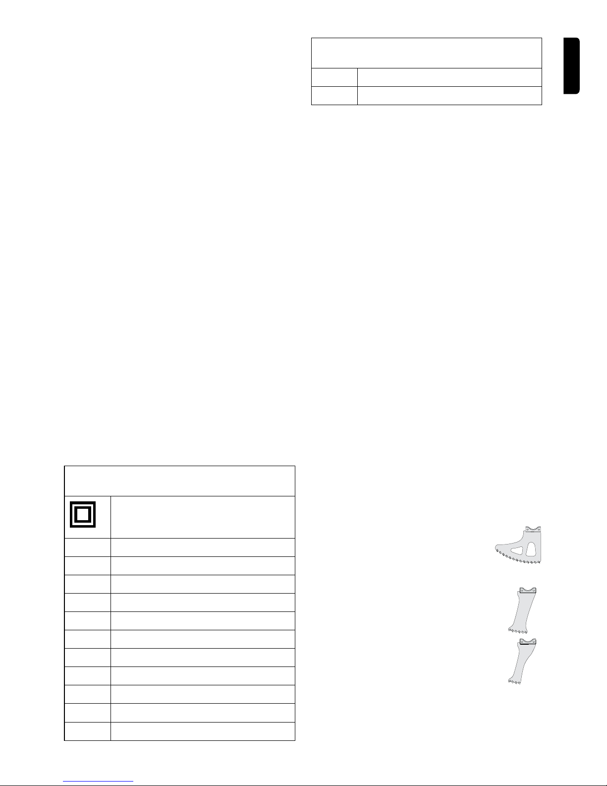
The tool can be tted with a range of blades to
best suit different applications.
Denitions: Safety Guidelines
Thedenitionsbelowdescribethelevelofseverity
for each signal word. Please read the manual and
pay attention to these symbols.
DANGER: Indicates an imminently hazardous
situation which, if not avoided, could result in death
or serious injury.
WARNING: Indicates a potentially hazardous
situation which, if not avoided, could result in death
or serious injury.
CAUTION: Indicates a potentially hazardous
situation which, if notavoided, may result in minor
or moderate injury.
CAUTION: Used without the safety alert symbol
indicates a potentially hazardous situation which, if
not avoided, may result in property damage.
Denotes risk of electric shock.
IMPORTANT INCORRECT USE OF THE
AS170 MAY LEAD TO PREMATURE WEAR AND/
OR DAMAGE. PLEASE READ THESE USER
INSTRUCTIONS CAREFULLY BEFORE USE TO
ENSURE CORRECT OPERATION.
2. GENERAL SAFETY RULES
WARNING! Read all safety warnings and all
instructions. Failure to follow all instructions listed
below,mayresultinelectricshock,reand/or
seriouspersonalinjury.
SAVE THESE INSTRUCTIONS
1) Work area
• Keep work area clean and well lit. Cluttered
and dark areas invite accidents.
• Do not operate power tools in explosive
atmospheres, such as in the presence of
ammableliquids,gasesordust.Power
tools create sparks which may ignite the dust
or fumes.
• Keepbystanders,children,andvisitors
away while operating a power tool.
Distractions can cause you to lose control.
2) Electrical Safety
• DoubleInsulatedtoolsareequippedwith
apolarizedplug(onebladeiswiderthan
theother.)Thisplugwilltinapolarized
outletonlyoneway.Iftheplugdoesnott
fully in the outlet, reverse the plug. If it still
doesnott,contactaqualiedelectrician
to install a polarized outlet. Do not change
the plug in any way. Double Insulation
eliminates the need for the three wire
grounded power cord and grounded power
supply system.
• Avoidbodycontactwithgroundedsurfaces
such as pipes, radiators, ranges and
refrigerators. There is an increased risk of
electric shock if your body is grounded.
• Don’t expose power tools to rain or wet
conditions. Water entering a power tool will
increase the risk of electric shock.
• Donotabusethecord.Neverusethecord
to carry the tools or pull the plug from an
outlet. Keep cord away from heat, oil, sharp
edges or moving parts. Replace damaged
cords immediately. Damaged cords increase
the risk of electric shock.
• When operating a power tool outside, use
an outdoor extension cord marked ”W- A”or
eNGLISH 2

“W.” These cords are rated for outdoor use
and reduce the risk of electric shock.
3) Personal Safety
• Stay alert, watch what you are doing and
use common sense when operating a power
tool. Do not use tool while tired or under the
inuenceofdrugs,alcohol,ormedication.
A moment of inattention while operating power
toolsmayresultinseriouspersonalinjury.
• Dress properly. Do not wear loose clothing
or jewelry. Contain long hair. Keep your
hair, clothing, and gloves away from
moving parts.Looseclothes,jewelry,orlong
hair can be caught in moving parts.
• Avoid accidental starting. Be sure switch
isoffbeforepluggingin. Carrying tools with
yourngerontheswitchorpluggingintools
that have the switch on invites accidents.
• Removeadjustingkeysorwrenchesbefore
turning the tool on. A wrench or a key that is
left attached to a rotating part of the tool may
resultinpersonalinjury.
• Do not overreach. Keep proper footing
andbalanceatalltimes. Proper footing and
balance enables better control of the tool in
unexpected situations.
• Usesafetyequipment.Alwaysweareye
protection.Dustmask,non-skidsafetyshoes,
hard hat, or hearing protection must be used
for appropriate conditions.
4) Tool Use and Care
• Use clamps or other practical way to secure
andsupporttheworkpiecetoastable
platform. Holding the work by hand or against
your body is unstable and may lead to loss of
control.
• Do not force tool. Use the correct tool for
your application. The correct tool will do the
jobbetterandsaferattherateforwhichitis
designed.
• Do not use tool if switch does not turn it on
or off. Any tool that cannot be controlled with
the switch is dangerous and must be repaired.
• Disconnect the plug from the power source
beforemakinganyadjustments,changing
accessories, or storing the tool. Such
preventive safety measures reduce the risk of
starting the tool accidentally.
• Store idle tools out of reach of children
and other untrained persons. Tools are
dangerous in the hands of untrained users.
• Maintain tools with care. Keep cutting tools
sharp and clean. Properly maintained tools,
with sharp cutting edges are less likely to bind
and are easier to control.
• Checkformisalignmentorbindingof
movingparts,breakageofparts,and
any other condition that may affect the
tools operation. If damaged, have the tool
servicedbeforeusing. Many accidents are
caused by poorly maintained tools.
• Use only accessories that are
recommendedbythemanufacturerforyour
model. Accessories that may be suitable for
one tool, may become hazardous when used
on another tool.
5) Service
• Toolservicemustbeperformedonly
byqualiedrepairpersonnel. Service
ormaintenanceperformedbyunqualied
personnelcouldresultinariskofinjury.
• When servicing a tool, use only identical
replacement parts. Follow instructions in
the Maintenance section of this manual.
Use of unauthorized parts or failure to follow
Maintenance Instructions may create a risk of
electricshockorinjury.
3. SPECIFIC SAFETY RULES
1. Hold tool by insulated gripping surfaces when
performing an operation where the cutting tool
may contact hidden wiring or its own cord.
Contactwitha“live”wirewillmakeexposedmetal
partsofthetool“live”andshocktheoperator.
2. Remove adjusting tools such as Allen & Ian
keys and wrenches before operating the tool.
3. Do not operate the tool with any attachment
other than those recommended in this instruction
manual.
4. Only use the tool with the correct voltage, as
speciedinthetoollable.
5. Never start a tool under load. Start the tool before
engaging the work piece.
E
N
G
eNGLISH 3

E
N
G
6.Neverstartoroperatethetoolwithngersor
otherobjectsthroughtheholesintheblades.
7. Use care when handling blades during and
after use. The blades and some areas of the tool
become hot in use.
8. Always ensure that before cutting there are no
hazards such as electrical wiring, pipes or insulation
in the area to be cut.
9. Allow for resting periods to ease the effect of
the vibration of the tool. Use work gloves to minimise
vibration effect on the body.
10. Ensure the dust extraction equipment is
connected and properly used.
11. Keep handles dry, clean and free from oil and
grease.
12. If the guard or other part appears to be
damaged, it should be carefully checked to
determine that it will operate properly and perform its
intended function.
13. The use of any accessory or attachment other
than those recommended in this instruction manual
maypresentariskofpersonalinjury.
14. Do not force the tool. It is designed to operate
with moderate effort. Overheating of the drive
system and motor can occur if the tool is overloaded.
15.Alwaysoperatethetoolholdingitwithboth
hands.
SYMBOLS The following show the symbols used
in this manual
Class 2 Construction (Double
Insulation used throughout, no
provision for earthing.)
VAC volts alternating current
A amperes
Hz hertz
W watt
N0no load speed
rpm revolutions per minute
dB decibels
Nm newton meters
m meters
m/s meters per second
mm millimeters
SYMBOLS The following show the symbols used
in this manual
kg-m kilogram meters
ft-lb foot pounds
4. FUNCTIONAL DESCRIPTION
4.1 AS170 TOOL DESCRIPTION
The AS170 is designed to cut rigid materials such
asmortar,clayredbricks,plasterboard,breboard,
weatherboard and wood. The AS170 uses a variety
of blades to suit the material being cut. Blades may
also be changed to suit the required depth or length
of cut.
The blades are driven via conrods and a camshaft,
whichisbelt-driven.TheV-beltisdesignedtoallow
someslipincaseofthebladesjamming.The belt
tension must be checked after the rst 5 hours
of use. It is easily tightened by removing the plastic
coverandistensionedusingtheadjustableidler
pulley (see section 7.2).Blades are mounted to the
conrods using high tensile Allen™ head bolts.
A replaceable metal guard is provided to limit the
maximum cutting depth and prevent the blade
mounts from damaging the surface of the material
being cut. Shock and vibration to the operator are
reducedbyarubber-mountedtophandle.Thetop
handle is also designed for comfort when used in a
variety of cutting orientations. The rubber bushes on
the top handle can be replaced if they become worn
or damaged.
4.2 BLADE DESCRIPTION
The AS170 uses a variety of blades to cut different
materialsanddifferentproles.
General Purpose blades use Tungsten
Carbide teeth and are suited for working
general masonry and “in the ground” cutting.
General Purpose blades are designed to cut
to a depth of 115mm (4 1/2”).
Plunge blades use Tungsten Carbide teeth
and have a maximum cutting depth of
120mm (4 3/4”). Mortar plunge blades can cut
slots of 75mm (3”) in length.
Switch Box blades use Tungsten Carbide
teeth and have a maximum cutting depth of
120mm (4 3/4”). Suitable for installing small
electrical switch boxes into plaster, brick/
masonry walls.
eNGLISH 4

E
N
G
eNGLISH 5
PARTS
KEY NO. DESCRIPTION QUANTITY
1 Screw - Belt Cover , M4 X 12 4
2 Screw - Blade , M6 X 10 4
3 Brush - Cover 2
4Washer - Step 1
5 Nut - Nyloc M6 1
6 Brush - Carbon 2
7 Clip - Internal 2
8 Pin 2
9 Pulley - Tension including Bearing - 6961
10 Pulley - Power 1
11 Pulley - Drive 1
12 Belt 1
13 Bush 4
14 Guard 1
15 Handle - Top1
16 Cover - Belt 1
17 Housing 1
18 Motor - (Regional) 1
29 ELECTRICAL PLUG (REGIONAL) 1
20 Boot - Dust Extraction Funnel 1
21 Bracket - Dust Extraction Fitting1
22 Switch - (Regional) 1
23 Cover - Vent 1
24 General Purpose Blades1
TM
ALLSAW™ 160

E
N
G
eNGLISH 6
PARTS
KEY NO. DESCRIPTION QUANTITY
1 Screw - Belt Cover , M4 X 12 4
2 Screw - Blade , M6 X 10 4
3 Brush - Cover 2
4Washer - Step 1
5 Nut - Nyloc M6 1
6 Brush - Carbon 2
7 Clip - Internal 2
8 Pin 2
9 Pulley - Tension including Bearing - 6961
10 Pulley - Power 1
11 Pulley - Drive 1
12 Belt 1
13 Bush 4
14 Guard 1
15 Handle - Top1
16 Cover - Belt 1
17 Housing 1
18 Motor - (Regional) 1
29 ELECTRICAL PLUG (REGIONAL) 1
20 Boot - Dust Extraction Funnel 1
21 Bracket - Dust Extraction Fitting1
22 Switch - (Regional) 1
23 Cover - Vent 1
24 General Purpose Blades1
TM
ALLSAW™ 160
1 Screw - Belt Cover , M4 X 12 4
2 Screw - Blade , M6 X 10 4
3 Brush - Cover 2
4 Washer - Step 1
5 Nut - Nyloc M6 1
6 Brush - Carbon 2
7 Clip - Internal 2
8 Pin 2
9 Pulley - Tension including Bearing - 696 1
10 Pulley - Power 1
11 Pulley - Drive 1
12 Belt 1
13 Bush 4
14 Guard 1
15 Handle - Top 1
16 Cover - Belt 1
17 Housing 1
18 Motor - (Regional) 1
19 ELECTRICAL PLUG (REGIONAL) 1
20 Boot - Dust Extraction Funnel 1
21 Bracket - Dust Extraction Fitting 1
22 Switch - 1
24 General Purpose Blades 1

Headjoint blades are shortened blades
used for headjoint mortar removal
without damaging surrounding brick
work. Maximum cutting depth of 35mm
(1 3/8”).
Heritage blades are similar to Headjoint
blades but with a reduced cutting width
of 3mm (1/8”), designed for thin joints
(butterjoints). Maximum cutting depth of
35mm (1 3/8”).
XL General Purpose blades Cutting depth
up to 170mm (6 3/4”) without overcutting.
Depth: 170mm Width: 7.2mm
XL Wood blades Efcient and safe cutting of
wood and composite materials.
Depth: 170mm Width: 7.2mm
Caulking Blades
Ideal to remove caulking between concrete
panels. E.g Tilt up, parking lots.
*Available in 3 widths. 1/2” 1” 2”
NOTE: ALL blades can be re-
sharpened. If not excessively worn.
6. OPERATION
6.1 Setup
The AS170 is supplied ready for operation. However
in some cases the blades may need to be changed
to suit the application.
Before changing
blades, the guard
around the blade
mounts must be levered
gently out of its groove
at the front of the tool
and swung away to
give access to the cap
screws. (See Fig.1) Guard
Fig.1
Use the “Ian key”
supplied to loosen and
remove the cap screws
securing the blades,
then remove the blades
as shown in g.2.
Ian Key
Fig.2
Hold near
end
Torque
indicator
coil
Select the correct blades for the cutting task and
mounteachwiththeircapscrews.Verifythatthe
surfaces of the blade mounts, conrod thread and
screws are clean and free of grit or lubricant before
tting.Ensuretheguardcanbeclosedbeforexing
thebladestotheconrod(Seeg.2).
NOTE: Always use matched pairs of blades.
Never mix used blades with new blades. Use
only the bolts supplied with the tool.
Use the “Ian key” (see
g.2), to tighten the
blade mounting screws
until the torque indicator
coil deects sufciently
so that the sides meet.
The “Ian Key” will
tighten the bolts to the
required 16Nm (11.5
ft lb).
Fig.3
NOTE: Blades are a wearing part. In normal
operation, blade life may vary with the hardness
of materials cut.
CAUTION:
Do not operate the tool
if the blades are loose.
Operation with loose
blades will severely
damage the blade
mount & bolts requiring
repair.
Check that the teeth of
the blades are lightly
contacting, or within
approximately 1.5 mm
(1/16”) of contacting
each other (fig.4).
Fig.4
90o1mm Max
(1/16”)
If the gap between the blades is too large, remove
andgentlybentinwardtoadjustthegap.
Ensure that both blades are aligned vertically to the
tool(Seeg.4).
CAUTION: If the blades rub against each
other anywhere other than within 25 mm/1”
of the cutting edge, or contact force is high,
it is possible to overload the tool and cause
premature belt wear.
Swing the guard to its groove at the front of the
tool and snap it into place. (See g.1)
6.2 Operation
E
N
G
eNGLISH 7

E
N
G
CAUTION: During
operation the AS170
may cause hand-arm
vibration, which can result
in fatigue or discomfort
after long periods of
continuous use. Vibration
will increase with the
hardness of material.
Do not operate the
tool if discomfort is
experienced, and ensure
that sufcient rest periods
are taken during cutting.
For further information,
contact the manufacturer.
Fig.5
Fig.6
Before attempting to operate the tool, please ensure
that the safety section of this manual has been
consulted.
Apply protective hearing, breathing, eyes and body
protection as appropriate.
With the blades secured and the tool switch OFF,
plug the tool into the power socket.
CAUTION:
Do not block the
cooling intake vents
or ingest dust or
debris at the rear of
the motor as this may
cause the motor to
overheat. If working
in dusty conditions, it
is recommended that
the vents be regularly
cleaned with an air
blast. (See fig.7)
Fig.7
Hold the tool by both the top handle and the motor
housing. (Fig.5 & 6)
Tostartthecut,holdthetoolrmlyinyourhands
and apply the middle of the blade cutting edge to
the work, keeping in mind that the direction of cut is
towards the rear of the blades.
While cutting, move the tool and blade in a slow
“sawing”motion,whichimprovesthecutrate,
reducesconcentratedheatbuild-upandevensthe
wearontheblades.(Seeg.8&9)
Direction of cut
Fig.8
Direction of cut
Fig.9
CAUTION: Do Not allow the forward or rear end
of the blades to hammer onto hard surfaces
(shown in gs: 10,11 & 13) as this will damage
the blades and tool. If unintentional hammering
occurs, stop the tool or withdraw it from the cut
immediately.
When using any of the blade types, avoid
hammering of the ends of the blades into the ends
of the cut by using a slow rocking and sweeping
motion. For best performance try to ensure that the
teeth are the only part of the blade in contact with
the workpiece.
CAUTION: Take care when setting the tool down
to avoid chipping the tungsten carbide teeth.
eNGLISH 8

Fig.10
“Hammering!”
Fig.11
“Hammering!”
Clearance
each end
Fig.12
When using the Mortar Plunge blades, the cut
should have enough clearance on each end (shown
ing:12),toensurethatnohammeringoftheblade
endsoccurs(asshowning.13).
“Hammering!”
Fig.13
7. MAINTENANCE
WARNING: To reduce the risk of serious
personal injury, turn the tool off and disconnect
tool from the power source before making any
adjustments or removing/installing attachments
or accessories.
Before reconnecting the tool, depress and release
the trigger switch to ensure that the tool is turned off.
To assure product SAFETY and RELIABILITY,
repairs,maintenanceandadjustment(including
brush inspection and replacement) should be
performed by an ARBORTECH authorised service
center. Always use identical replacement parts.
7.1 Motor
Cleaning
CAUTION: Blowing dust and grit out of the
motor and switch actuator using clean,
dry compressed air is a necessary regular
maintenance procedure. Dust and grit particles
often accumulate on interior surfaces and can
cause premature failure. Not regularly cleaning
the AS170 will affect the tools warranty.
CAUTION: ALWAYS WEAR SAFETY GLASSES
when using or cleaning this tool.
Never use solvents or other harsh chemicals for
cleaning the non-metallic parts of the tool. Use a
clean, dry cloth only.
Lubrication
ARBORTECH tools are properly lubricated at the
factory and are ready for use.
Accessories
eNGLISH 9
E
N
G

E
N
G
Toreducetheriskofinjury,onlyARBORTECH,
accessories should be used with this product.
Recommended accessories for use with your tool
are available at extra cost from your local dealer or
authorised service center.
Repairs
If you need any assistance in locating any
accessory, or general tool query please contact
ARBORTECH. www.arbortechusa.com or free call
866-517-7869.
Brushes
TheAS170isttedwithAuto-cutoffbrushes.When
the brushes are worn below minimum length they
stop tool operation reducing internal motor damage.
Contact your local dealer or authorised service
center for brush replacement.
7.2 V Belt and Pulleys
CAUTION: The V-Belt should be re-tensioned
after the rst 5 hours of use.
To access these items, remove the 4 screws holding
the plastic cover on the right side of the tool (see
g.14).Inspectthebeltforcorrecttensionandsigns
of damage. If tensioning is required, loosen the the
tension idler nut (one turn only). Slide the tension
idler outward to increase the tension to the value
noted in the General Specications in Section 3
andre-tighten.Ifbeltreplacementisrequired,loosen
thetensioneridler,replacethebeltandre-tension
theidlerasspecied.
Tension Idler
Cover
Fig.14
If excessive slipping has occurred, the pulleys
can become worn. A worn pulley is evidenced by
thegroovehavinglostitswelldened“V”shape,
resultinginaroundedorattenedgroove.Toreplace
either pulley, contact your ARBORTECH authorised
service centre.
7.3 Blade Mount Bolts and Threads
The blade cap screws should be regularly checked
for correct torque (18Nm.)(13.2 ft lb).Whenever
blades are changed, the bolt and conrod threads
should be checked to ensure they are not worn or
lledwithdebris.UseonlygenuineARBORTECH
spares and do not lubricate bolts, threads or conrod
mating surfaces.
Fig.15
CAUTION: DO NOT operate the tool with loose
blades. If blades should come loose while
operating, the blade mounts and threads can
become damaged, requiring signicant repairs
to the tool.
7.4 Tooth Sharpness
With use, the blades will become dull and the cutting
performance will decrease. This can be largely
restoredbyre-sharpeningtheteeth.Tore-sharpen
blade teeth, use the ARBORTECH Sharpening
disk (BLA.FG.SHARP001) Occasionally, if very
hard materials are cut, or the teeth impact a hard
surface at an odd angle, teeth may become chipped
or broken. The blades can still be used, but cutting
performance will be reduced.
If“blueing”ofthebladeperipheryoccurs,the
blades are running too hot. This occurs when the
blades become worn, too much force being used,
insufcient“sweeping”motionbytheoperator,or
material being too hard.
IMPORTANT To ensure optimal performance and
reduce load on motor, Blades should be kept sharp.
8. ACCESSORIES
8.1 Dust Extraction
TheAS170shouldbettedwithadustextraction
funnel,whichsignicantlyreducesairborneand
heavy dust when used correctly. It consists of a
ttingattachedtotheundersideofthealuminium
housingandanadjustableextractionfunnelwhich
eNGLISH 10

isreplaceable.Thedustextractionttinghasa
standard 30mm (1 3/16”) bore.
NOTE: Failure to use the dust extraction funnel
when cutting masonry materials will cause
excessive wear of electrical components.
Damage caused by dust will lead to premature
failure of the motor, which will affect the
warranty.
CAUTION: Verify that the vacuum machine being
used has a lter system appropriate for the
material being cut. Incorrect ltration can result
in inadequate dust control and also possible
damage to the vacuum machine.
Dust extraction funnel
9. SPECIFICATIONS
ITEM SPECIFICATION
Cutting depth/width 120mm (4 3/4”)/6.5mm
(1/4”), (depending on
blade/material)
Weight, with cutting
blades
4.3kg (9.5lb)
Dimensions without
blades
450 mm (17 11/16”) L
75 mm (3”) W
240 mm (9 7/16”) H
No load speed n05100 rpm
Electrical rating,
nominal
120V AC/DC
60Hz
13 A
ITEM SPECIFICATION
Dust extraction vacuum
hose interface
30mm (1 3/16”) ID, EN
60335-2-69
Belt tension 1.5 mm (1/16”) maxi-
mum mid-span deec-
tion with
25 N (2.5 kg) (5lb)
deection force
Blade mount bolt
torque
18 Nm (1.8 kg-m),
(13.2ft-lb), un-lubri-
cated
10. WARRANTY AND SERVICE
For warranty repair, inspection, service and spare
parts, please contact your place of purchase,
or
Check out our website www.arbortechusa.com to
locate a dealer or service agent in your area
or
Contact us directly:
Arbortech USA Address
80 Erdman Way, Suite 200Leominster, MA
04153Telephone(Ofce):978-466-7945TollFree:
866-517-7869TollFreeUSFax:866-515-8104
E
N
G
eNGLISH 11

E
N
G
eNGLISH 12
ITEM
SYMPTOM CHECK/REMEDY
1 Motor overheating • Verify that all cooling vents are not obstructed by operators hand, debris
in vents, or other. Remedy or clean as required.
• Verify blades are not rubbing against each other with excessive force,
either at cutting edge or close to blade mounts.
• Blades may be worn and overheating. Replace as required.
• Check that belt tension is not excessive.
• Check that bearings have not failed by removing plastic side cover and
belt and rotating both pulleys independently checking for roughness. The
power pulley should rotate easily and smoothly. The driven pulley should
rotate smoothly but will have a “springy” feel, wanting to stay in either of 2
positions.
• Verify that the motor housing is secure with the tool. If loose, refer to
authorised service centre immediately.
2 Noisy operation or unusual
vibration
• Blades loose -tighten blade mount bolts
• Blade failure - replace blade set
• Leaf spring failure - contact authorized service centre
• Bearing failure - contact authorized service centre.
• Gearbox failure - contact authorized service centre.
• Handle rubber mounts damaged or worn - replace.
3 Handle rubber mounts
damaged or worn
• Replace
4 One or both conrods/blades
loose, even when mounting
bolts tightened
• Leaf spring failure - contact ARBORTECH authorised service centre.
5 Tool running and blades not
moving
• Loose belt or broken belt- re-tension or replace as necessary.
• Worn belt - replace belt.
7 Blades continually comming
loose
• Check the blade bolt holes. If bolt holes are elongated replace blades
8 Worn pulleys • Contact ARBORTECH authorised service centre.
9 Slow cutting performance • Teeth worn, chipped or lost. Sharpen or replace blade.
• Belt slipping.
10 Blades rubbing against each
other with excessive force
• Attempting to cut material which is too hard.
11 Blades rubbing together with
excessive force.
• Remove blade/s and bend slightly to correct.
12 Blade teeth chipped or lost.
·
• Occurs occasionally if hard material is encountered, or if the “back side”
of teeth are impacted.
• Care not taken in setting tool down on teeth on hard surfaces or loose in
tool box.
• Worn blades will start to become hot in certain areas, causing teeth to de-
bond - replace blades.
• Material too hard.
13 Loose top handle. • Worn or damaged rubber bushes - replace.
11. trouBlEsHootING
This fault diagnosis is intended for use by persons familiar with mechanical devices, and provides a basic
capability to maintain the tool. To correct the user serviceable faults, refer to the Maintenance section of this
manual. The more complex repairs as noted below, must be performed by an authorised service centre.

E
N
G
eNGLISH 13
ITEM
SYMPTOM CHECK/REMEDY
14 Blades “blueing”. • Worn teeth - replace blades.
• Excessive force being used.
• Insufcient “sawing” motion by the operator.
• Material too hard.
Blades rubbing together with excessive force (see section 8).
15 Blade mounting bolts not
tightening fully. • Threads on bolts stripped - replace bolts not tightening.
16 Threads on tool stripped • Contact your ARBORTECH authorized service center.
17 Tool will not run. • The AS170 is tted with Auto cut off brushes.
• Check brushes are not damaged or excessively worn - replace Contact
your ARBORTECH authorized service centre.
Other manuals for AS170
2
Table of contents
Other Arbortech Saw manuals

Arbortech
Arbortech ALLSAW AS175 Setup guide

Arbortech
Arbortech AS200X Setup guide

Arbortech
Arbortech ALLSAW AS175 Setup guide

Arbortech
Arbortech ALLSAW AS175 Setup guide

Arbortech
Arbortech AS170 User manual

Arbortech
Arbortech ALL.FG.175240.00/40 Setup guide

Arbortech
Arbortech AS200X Setup guide

Arbortech
Arbortech AS160 User manual

Arbortech
Arbortech AS170 User manual