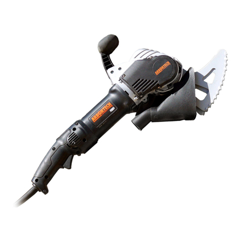
Arbortech ALLSAW AS175 Setup guide

Double Insulation used throughout, no
provision for earthing.
www.arbortechtools.com
OWNER’S INSTRUCTION MANUAL
ALLSAW AS175 BRICK & MORTAR SAW ALL.FG.175240.00
Please read this manual carefully to ensure correct operation and care of the machine. If you use the AS175
correctly, it will provide you with years of reliable service saving you time and money.

TABLE OF CONTENTS
1. INTRODUCTION.........................................................................................................................................................1
2. GENERAL POWER TOOL SAFETY WARNINGS......................................................................................................1
1) Work area ...................................................................................................................................................................1
2) Electrical safety..........................................................................................................................................................1
3) Personal safety...........................................................................................................................................................2
4) Power tool use and care ............................................................................................................................................2
5) Service .......................................................................................................................................................................2
6) Safety instructions for reciprocating saws .................................................................................................................2
3. FUNCTIONAL DESCRIPTION...................................................................................................................................3
1) AS175 Tool description ..............................................................................................................................................3
2) Blade Description.......................................................................................................................................................3
4. ASSEMBLY ................................................................................................................................................................4
5. OPERATION...............................................................................................................................................................4
1) Setup..........................................................................................................................................................................4
2) Dust Extraction...........................................................................................................................................................5
3) Specifications.............................................................................................................................................................6
4) How to Use.................................................................................................................................................................6
6. MAINTENANCE .........................................................................................................................................................7
1) Motor ..........................................................................................................................................................................7
2) Belt and Pulleys..........................................................................................................................................................8
3) Blade Mount Bolts and Threads.................................................................................................................................8
4) Blades and Teeth .......................................................................................................................................................8
7. WARRANTY AND SERVICE.......................................................................................................................................8
8. TROUBLESHOOTING................................................................................................................................................9
Please read these instructions before you use your AS175 Brick & Mortar Saw

1
1. INTRODUCTION
The Arbortech AS175 Brick & Mortar Saw is
designed and manufactured in Australia, using only
the highest quality components and manufacturing
processes.
The unique patented orbital cutting action of two
reciprocating blades, allows cutting of brick, mortar
and masonry faster than traditional reciprocating
saws.
This cutting action also produces minimal amounts
of airborne dust, offering a safe and controllable
operation, with the ability to cut to a depth of
120mm (4 3/4”), cut square corners and make
variable width cuts. The AS175 is ideally suited to a
variety of tasks including:
• removal of mortar for tuck pointing of brick walls.
• removal of single bricks from walls.
• cutting of bricks without damage to adjacent
areas or “blow-out” stitching, keying or toothing
of brick walls“chasing” cuts for conduits and
similar items into walls.
• cutting holes in walls or other surfaces.
• nishingcornercutsinwalls.
The tool can be tted with a range of blades to best
suit different applications.
Denitions: Safety Guidelines
The definitions below describe the level of severity
for each signal word. Please read the manual and
pay attention to these symbols.
DANGER: Indicates an imminently hazardous
situation which, if not avoided, will result in death or
serious injury.
WARNING: Indicates a potentially hazardous
situation which, if not avoided, could result in death or
serious injury.
CAUTION: Indicates a potentially hazardous
situation which, if not avoided, may result in minor or
moderate injury.
CAUTION: Used without the safety alert symbol
indicates a potentially hazardous situation which, if not
avoided, may result in property damage.
Denotes risk of electric shock.
2. GENERAL POWER TOOL SAFETY
WARNINGS
WARNING: read all safety warnings,
instructions, illustrations and specications
provided with this power tool. Failure to follow all
instructions listed below may result in electric shock,
fire and/or serious injury.
Save all warnings and instructions for future
reference.
The term “power tool” in the warnings refers to your
mains-operated (corded) power tool.
1) Work area
a) Keep work area clean and well lit. Cluttered and
dark areas invite accidents.
b) Do not operate power tools in explosive
atmospheres, such as in the presence of
ammable liquids, gases or dust. Power tools
create sparks which may ignite the dust or fumes.
c) Keep children and bystanders away while
operating a power tool. Distractions can cause you
to lose control
2) Electrical safety
a) Power tool plugs must match the outlet. Never
modify the plug in any way. Do not use any
adapter plugs with earthed (grounded) power
tools.Unmodiedplugsandmatchingoutletswill
reduce risk of electric shock
b) Avoid body contact with earthed or grounded
surfaces such as pipes, radiators, ranges and
refrigerators. There is an increased risk of electric
shock if your body is earthed or grounded.
c) Do not expose power tools to rain or wet
conditions. Water entering a power tool will
increase the risk of electric shock.
d) Do not abuse the cord. Never use the cord for
carrying, pulling or unplugging the power tool.
Keep cord away from heat, oil, sharp edges
or moving parts. Damaged or entangled cords
increase the risk of electric shock.
e) When operating a power tool outdoors, use an
extension cord suitable for outdoor use. Use of
a cord suitable for outdoor use reduces the risk of
electric shock.
f) If operating a power tool in a damp location is
unavoidable, use a residual current device (RCD)
protected supply. Use of an RCD reduces the risk
of electric shock.

2
3) Personal safety
a) Stay alert, watch what you are doing and use
common sense when operating a power tool. Do
not use a power tool while you are tired or under
the inuence of drugs, alcohol or medication. A
moment of inattention while operating power tools
may result in serious personal injury.
b) Use personal protective equipment. Always wear
eye protection. Safety equipment such as dust
mask, nonskid safety shoes, hard hat, or hearing
protection used for appropriate conditions will
reduce personal injuries.
c) Prevent unintentional starting. Ensure the
switch is in the off-position before connecting to
power source and or battery pack, picking up or
carrying the tool. Carrying power tools with your
finger on the switch or energising power tools that
have the switch on invites accidents.
d) Remove any adjusting key or wrench before
turning the power tool on. A wrench or a key left
attached to a rotating part of the power tool may
result in personal injury.
e) Do not overreach. Keep proper footing and
balance at all times. This enables better control of
the power tool in unexpected situations.
f) Dress properly. Do not wear loose clothing or
jewellery. Keep your hair, clothing and gloves
away from moving parts. Loose clothes, jewellery
or long hair can be caught in moving parts.
g) If devices are provided for the connection of dust
extraction and collection facilities, ensure these
are connected and properly used. Use of these
devices can reduce dust-related hazards.
h) Do not let familiarity gained from frequent use
of tools allow you to become complacent and
ignore tool safety. A careless action can cause
severe injuries within a fraction of a second.
4) Power tool use and care
a) Do not force the power tool. Use the correct
power tool for your application. The correct power
tool will do the job better and safer at the rate for
which it was designed.
b) Do not use the power tool if the switch does not
turn it on and off. Any power tool that cannot be
controlled with the switch is dangerous and must be
repaired.
c) Disconnect the plug from the power source and/
or the battery pack from the power tool before
making any adjustments, changing accessories,
or storing power tools. Such preventive safety
measures reduce the risk of starting the power tool
accidentally.
d) Store idle power tools out of the reach of
children and do not allow persons unfamiliar
with the power tool or these instructions to
operate the power tool. Power tools are dangerous
in the hands of untrained users.
e) Maintain power tools and accessories. Check
for misalignment or binding of moving parts,
breakage of parts and any other condition
that may affect the power tools operation. If
damaged, have the power tool repaired before
use. Many accidents are caused by poorly
maintained power tools.
f) Keep cutting tools sharp and clean. Properly
maintained cutting tools with sharp cutting edges
are less likely to bind and are easier to control.
g) Use the power tool, accessories and tool bits etc.
in accordance with these instructions and in the
manner intended for the particular type of power
tool, taking into account the working conditions
and the work to be performed. Use of the power
tool for operations different from those intended
could result in a hazardous situation
h) Keep handles and grasping surfaces dry, clean
and free from oil and grease. Slippery handles and
grasping surfaces do not allow for safe handling
and control of the tool in unexpected situations.
5) Service
a) Have your power tool serviced by a qualied
repair person using only identical replacement
parts. This will ensure that the safety of the power
tool is maintained.
6) Safety instructions for
reciprocating saws
a) Hold the power tool by insulated gripping
surfaces, when performing an operation where
the cutting accessory may contact hidden wiring
or its own cord. Cutting accessory contacting a
“live” wire may make exposed metal parts of the
power tool “live” and could give the operator an
electric shock.
b)
Use clamps or another practical way to secure
and support the workpiece to a stable platform.
Holding the workpiece by hand or against your body
leaves it unstable and may lead to loss of control.
c) Do not operate the tool with any attachment
other than those recommended in this instruction
manual.
d) Only use the tool with the correct voltage, as
speciedinthetoollabel.
e) Never start a tool under load. Start the tool before
engaging the work piece.

3
f) Never start or operate the tool with ngers or
other objects through the holes in the blades.
g) Use care when handling blades during and after
use. The blades and some areas of the tool become
hot in use.
h) Always ensure that before cutting there are
no hazards such as electrical wiring, pipes or
insulation in the area to be cut.
i) Allow for resting periods to ease the effect of the
vibration of the tool. Use work gloves to minimise
vibration effect on the body.
j) Ensure the dust extraction equipment is
connected and properly used.
k) The use of any accessory or attachment other
than those recommended in this instruction
manual may present a risk of personal injury.
l) Do not force the tool. It is designed to operate with
moderate effort. Overheating of the drive system
and motor can occur if the tool is overloaded.
m)
Always operate the tool holding it with both hands.
SYMBOLS The following symbols are sed in this
manual and marking of this tool
Class 2 Construction (Double Insulation
used throughout, no provision for earthing.)
Read instruction manual
Wear hearing protection
Wear eyes protection
Wear breathing protection mask
V~ volts alternating current
A amperes
Hz hertz
W watt
N0no load speed
/min reciprocations
dB decibels
Nm newton metres
m metres
m/s metres per second
mm millimetres
kg-m kilogram metres
ft-lb foot pounds
3. FUNCTIONAL DESCRIPTION
1) AS175 Tool description
The AS175 is designed to cut rigid materials such as
mortar, clay fired bricks, plasterboard, fibreboard. The
AS175 uses a variety of blades to suit the material
being cut. Blades may also be changed to suit the
required depth or length of cut.
The blades are driven via conrods and a camshaft,
which is belt-driven. The belt drive designed to allow
some slip in case of the blades jamming. If excessive
belt slipping occurs, re-tensioning of the belt may
be required. It is easily tightened by removing the
plastic cover and is tensioned using the adjustable idler
pulley (see section 7.2). Blades are mounted to the
conrods using high tensile Allen™ head bolts.
A replaceable metal guard is provided to limit the
maximum cutting depth and prevent the blade mounts
from damaging the surface of the material being cut.
Shock and vibration to the operator are reduced by
a rubber-mounted top handle. The top handle is also
designed for comfort when used in a variety of cutting
orientations. The rubber bushes on the top handle can
be replaced if they become worn or damaged.
2) Blade Description
The AS175 uses a variety of blades to cut different
materials and different profiles.
General Purpose Blades use Tungsten
Carbide teeth and are suited for working
general masonry. General Purpose blades are
designed to cut to a depth of 115mm (4 1/2”).
Plunge Blades use Tungsten Carbide
teeth and have a maximum cutting depth of
120mm (4 3/4”). Mortar plunge blades can
cut slots of 75mm (3”) in length.
Switch Box Blades use Tungsten Carbide
teeth and have a maximum cutting depth of
120mm (4 3/4”). Suitable for installing small
electrical switch boxes into plaster, brick/
masonry walls.
Heritage Blades Ideal for mortar removal
on thin joints and heritage restoration. Depth
35mm (1 3/8”), Width 3mm (1/8” )
Headjoint Blades Ideal for mortar removal
on vertical joints. Depth 75mm (3”), Width
7.2mm (9/32” )
Caulking Blades Ideal to remove caulking
between concrete panels. E.g Tilt up,
parking lots. *Available in 3 widths (1/2”,
1” and 2”).
XL General Purpose Blades Cutting depth
up to 170mm (6 3/4”) without overcutting.
Tuckpointing Blades Used for removing the
mortar between bricks in restoration work.
Max. cutting Depth 35mm (1 3/8”)

4
4. ASSEMBLY
ITEM DESCRIPTION
1 Rear handle
2 Trigger switch
3 Lock-off lever
4 Lock on button
5 Top Handle
5
TITLE:
ASSEMBLY NO. DRAWING NO.
EST. MASS:
DRAWN BY:
DATE:
CHECKED:
APPROVED: SHEET:
ASSEMBLY NOTES:
CONFIDENTIAL
COPYRIGHT AND DESIGN
RIGHTS REMAIN THE SOLE
PROPERTY OF ARBORTECH
INDUSTRIES PTY LTD.
PROPRIETRY INFORMATION
DISCLOSURE OR
REPRODUCTION PROHIBITED
WITHOUT WRITTEN
APPROVAL FROM ARBORTECH
INDUSTRIES PTY LTD.
67 WESTCHESTER RD MALAGA
WESTERN AUSTRALIA 6062
PH. +618 9249 1944
12345678910111213
A
B
C
D
E
F
G
H
I
A
B
C
D
E
F
G
H
I
12345678910111213
A3
1 OF 3110079146.430 kg SCALE: 0.100BT
AS175-A001-00AS175-A001-01
ALL MATERIALS TO BE ROHS
COMPLIANT
09-Oct-18
AS175
AS180-A005-AA
UNSPECIFIED TOLERANCES
TO FOLLOW ISO-2768-F
DIMENSIONS IN MILLIMETRES
ARBORTECH INDUSTRIES PTY LTD
REV DETAILS APRVD DATE
A ISSUED FOR REVIEW
QTY.MATERIALPART NAMEPART NO.INDEX
1AISI_1020DRIVEN PULLEYAS175-P003-AC1
1AISI_1020TENSION IDLERAS175-P004-AA2
1AISI_4140DRIVE PULLEYAS175-P002-AB3
1AL6061RIGHT HAND HOUSINGAS175-P012-024
4FE40TPTR_7211_35
1NYLONbody_back_as180_a_c.prtBODY_BACK_AS180_A_C6
1NYLONbody_mid_as180_a_c.prtBODY_MID_AS180_A_C7
1PA6-GF30BELT COVERAS175-P021-018
1PA6-GF30VACUUM ADAPTERAS175-P010-AA9
1STAINLESS_STEEL_MARTENSITICSPRING GUARDAS175-P008-0110
2AS175-P009-0111
4M4X12_SCREW12
4TPTR_6010_113
5TPTR_6012_014
4TPTR_6014_015
2TPTR_6016_016
1TPTR_6019_017
2TPTR_6022_018
1TPTR_6024_019
1TPTR_6025_020
1TPTR_6026_021
2TPTR_6028_022
4TPTR_6029_023
1TPTR_6031_024
1TPTR_7087_225
2TPTR_7093_1
26
1TPTR_7205_027
1TPTR_8096_128
1TPTR_10011_229
2TPTR_AS_6008_030
1as170-a005-01.asmAS175-A005-0131
1as175-a001-ac.asmAS175-A003-AC32
1as175-p006-aa.prtAS175-P006-AA33
1as175_a004_01_top-handle.asmAS175_A004_01_TOP-HANDLE34
1AS180-P002-01AS180-P002-0135
1circlip_i19.prtCIRCLIP_I1936
1dwe4277-air-baffle.prtDWE4277-AIR-BAFFLE37
1O-RING-BS020O-RING-BS02038
1optibelt_epj.prtOPTIBELT_EPJ39
1optibelt_ph.prtOPTIBELT_PH40
1optibelt_pj260.prtOPTIBELT_PJ_EXT_IDLER41
1optibelt_pj280.prtAS175-P022-042
1tptr-9094-0-rh.asmTPTR_9094_0_RH43
1tptr_8119_7.asmTPTR_8119_744
1tptr_9094_0_lh.asmTPTR_9094_0_LH45
SCALE 0.500
1
TITLE:
ASSEMBLY NO. DRAWING NO.
EST. MASS:
DRAWN BY:
DATE:
CHECKED:
APPROVED: SHEET:
ASSEMBLY NOTES:
CONFIDENTIAL
COPYRIGHT AND DESIGN
RIGHTS REMAIN THE SOLE
PROPERTY OF ARBORTECH
INDUSTRIES PTY LTD.
PROPRIETRY INFORMATION
DISCLOSURE OR
REPRODUCTION PROHIBITED
WITHOUT WRITTEN
APPROVAL FROM ARBORTECH
INDUSTRIES PTY LTD.
67 WESTCHESTER RD MALAGA
WESTERN AUSTRALIA 6062
PH. +618 9249 1944
12345678910111213
A
B
C
D
E
F
G
H
I
A
B
C
D
E
F
G
H
I
12345678910111213
A3
2 OF 3110079146.430 kg SCALE: 0.250BT
AS175-A001-00AS175-A001-01
ALL MATERIALS TO BE ROHS
COMPLIANT
09-Oct-18
AS175
AS180-A005-AA
UNSPECIFIED TOLERANCES
TO FOLLOW ISO-2768-F
DIMENSIONS IN MILLIMETRES
ARBORTECH INDUSTRIES PTY LTD
REV DETAILS APRVD DATE
A ISSUED FOR REVIEW
4
3 2
TITLE:
ASSEMBLY NO. DRAWING NO.
EST. MASS:
DRAWN BY:
DATE:
CHECKED:
APPROVED: SHEET:
ASSEMBLY NOTES:
CONFIDENTIAL
COPYRIGHT AND DESIGN
RIGHTS REMAIN THE SOLE
PROPERTY OF ARBORTECH
INDUSTRIES PTY LTD.
PROPRIETRY INFORMATION
DISCLOSURE OR
REPRODUCTION PROHIBITED
WITHOUT WRITTEN
APPROVAL FROM ARBORTECH
INDUSTRIES PTY LTD.
67 WESTCHESTER RD MALAGA
WESTERN AUSTRALIA 6062
PH. +618 9249 1944
12345678910111213
A
B
C
D
E
F
G
H
I
A
B
C
D
E
F
G
H
I
12345678910111213
A3
2 OF 3110079146.430 kg SCALE: 0.250BT
AS175-A001-00AS175-A001-01
ALL MATERIALS TO BE ROHS
COMPLIANT
09-Oct-18
AS175
AS180-A005-AA
UNSPECIFIED TOLERANCES
TO FOLLOW ISO-2768-F
DIMENSIONS IN MILLIMETRES
ARBORTECH INDUSTRIES PTY LTD
REV DETAILS APRVD DATE
A ISSUED FOR REVIEW
5. OPERATION
1) Setup
WARNING: It is recommended that the tool
always be supplied via a residual current device with a
rated residual current of 30mA or less.
The AS175 is supplied ready for operation. However in
some cases the blades may need to be changed to suit
the application.
Before changing blades,
the guard around the
blade mounts must be
levered gently out of its
groove at the front of the
tool and swung away to
give access to the cap
screws. (See Fig.1) Guard
Fig.1
Use the “Ian key”
supplied to loosen and
remove the cap screws
securing the blades, then
remove the blades as
shown in Fig.2.
Ian Key
Fig.2
Hold near
end
Torque
indicator
coil
Select the correct blades for the cutting task and mount
each with their cap screws . Verify that the surfaces of
the blade mounts, conrod thread and screws are clean
and free of grit or lubricant before fitting. Ensure the
guard can be closed before fixing the blades to the
conrod (See Fig.2).
NOTE: Always use matched pairs of blades. Never
mix used blades with new blades. Use only the bolts
supplied with the tool.
Use the “Ian key” (see
Fig.2), to tighten the
blade mounting screws
until the torque indicator
coil deflects sufficiently
so that the sides meet.
The “Ian Key” will tighten
the bolts to the required
18Nm (13.2 ft lb).
Fig.3
NOTE: Blades are a wearing part. In normal
operation, blade life may vary with the hardness of
materials cut.

5
CAUTION:
Do not operate the tool
if the blades are loose.
Operation with loose
blades will severely
damage the blade mount &
bolts requiring repair.
Check that the teeth of
the blades are lightly
contacting, or within
approximately 1.5mm
(1/16”) of contacting each
other (Fig.4).
Fig.4
90o1.5mm Max
(1/16”)
If the gap between the blades is too large, remove and
gently bend inward to adjust the gap.
Ensure that both blades are aligned vertically to the tool
(See Fig.4).
CAUTION: If the blades rub against each other
anywhere other than within 25mm/1” of the cutting
edge, or contact force is high, it is possible to overload
the tool and cause premature belt wear.
Swing the guard to its groove at the front of the tool and
snap it into place. (See Fig.1)
2) Dust Extraction
The AS175 should be fitted with a Dust Boot and
used with a dust extraction vacuum. The Dust Boot
significantly reduces airborne dust exposure to the
user and bystanders. The Dust Boot can be fitted and
removed from the AS175 without tools, and with the
blades mounted. To fit the Dust Boot:
1. Insert the mounted blades through the split opening
on the topside of the Dust Boot
SCALE 1:2
SCALE 1:2
2. Pivot the Dust Boot until it engages with the dust
extractionttingandachievesaseatedoverlap
SCALE 1:2
3. Pinch and fold the front tabs of Dust Boot and press
underneath the guard rail.
SCALE 1:2
The dust extraction fitting on the underside of the
AS175 is designed to accommodate standard dust
extraction vacuums including a 35mm (1 3/8”) diameter
tapered vacuum and a 38mm (1 1/2”) diameter vacuum
fitting. Use an appropriate dust extraction system or
vacuum intended for masonry dust.
NOTE: Failure to use the Dust Boot when cutting
masonry materials will cause excessive wear of
electrical components. Damage caused by dust will
lead to premature failure of the motor, which will affect
the warranty.
CAUTION:
Verify that the vacuum machine being
used has a filter system appropriate for the material
being cut. Incorrect filtration can result in inadequate
dust control and also possible damage to the vacuum
machine.

6
3) Specications
ITEM SPECIFICATION
Cutting depth/width
120mm (4
3/4”)/6.5mm (1/4”)
depending on blade
Weight, with cutting
blades 4.3kg (9.5lb)
Dimensions without
blades
610 mm (24”) L
75 mm (3”) W
342 mm (13.5”) H
No load speed N05100 rpm
Power 1400W
Electrical rating, nominal 230-240 V~, 50Hz,
Dust extraction vacuum
hose interface
Suits vacuum hose
with 35mm diameter
internal taper fitting,
or 38mm diameter
external taper fitting.
Maximum mid-span belt
deflection
2mm (1/16”) with 15
N (1.5 kg) (3.4 lb)
deflection force
Blade mount bolt torque 18 Nm (1.8 kg-m),
(13.2ft-lb),
4) How to Use
CAUTION: During
operation the AS175 may
cause hand-arm vibration,
which can result in fatigue
or discomfort after long
periods of continuous use.
Vibration will increase with
the hardness of material.
Do not operate the tool if
discomfort is experienced,
and ensure that sufficient
rest periods are taken
during cutting. For further
information, contact the
manufacturer.
Fig.5
Fig.6
Apply protective hearing, breathing, eyes and body
protection as appropriate.
With the blades secured and the tool switch OFF, plug
the tool into the power socket.
CAUTION:
Do not block the cooling
intake vents or ingest
dust or debris at the
rear of the motor as this
may cause the motor
to overheat. If working
in dusty conditions, it
is recommended that
the vents be regularly
cleaned with an air blast.
(See Fig.7)
Fig.7
Hold the tool by both the top handle and the motor
housing. (Fig.5 & 6)
To start the cut, hold the tool firmly in your hands and
apply the middle of the blade cutting edge to the work,
keeping in mind that the direction of cut is towards the
rear of the blades.
While cutting, move the tool and blade in a slow
“sawing” motion, which improves the cut rate, reduces
concentrated heat build-up and evens the wear on the
blades. (See Fig.8 & 9)
Direction of cut
Fig.8
Direction of cut
Fig.9
CAUTION: Do not allow the forward or rear end
of the blades to hammer onto hard surfaces (shown in
figs: 10,11 & 13) as this will damage the blades and
tool. If unintentional hammering occurs, stop the tool or
withdraw it from the cut immediately.

7
When using any of the blade types, avoid hammering
of the ends of the blades into the ends of the cut by
using a slow rocking and sweeping motion. For best
performance try to ensure that the teeth are the only
part of the blade in contact with the workpiece.
CAUTION: Take care when setting the tool down
to avoid chipping the tungsten carbide teeth.
Fig.10
“Hammering!”
Fig.11
“Hammering!”
Clearance
each end
Fig.12
When using the Mortar Plunge blades, the cut should
have enough clearance on each end (shown in fig:12),
to ensure that no hammering of the blade ends occurs
(as shown in Fig.13).
“Hammering!”
Fig.13
6. MAINTENANCE
WARNING: To reduce the risk of serious personal
injury, turn the tool off and disconnect tool from the
power source before making any adjustments or
removing/installing attachments or accessories.
Before reconnecting the tool, depress and release the
trigger switch to ensure that the tool is turned off.
To assure product SAFETY and RELIABILITY, repairs,
maintenance and adjustment (including brush
inspection and replacement) should be performed by
an ARBORTECH authorised service center. Always use
identical replacement parts.
1) Motor
Cleaning
CAUTION: Blow dust and grit out of the motor and
switch actuator using clean, dry compressed air is a
necessary regular maintenance procedure. Dust and
grit particles often accumulate on interior surfaces and
can cause premature failure. Not regularly cleaning the
AS175 will affect the tools warranty.
CAUTION: ALWAYS WEAR SAFETY GLASSES
when using or cleaning this tool.
Never use solvents or other harsh chemicals for
cleaning the non-metallic parts of the tool. Use a clean,
dry cloth only.
Lubrication
ARBORTECH tools are properly lubricated at the factory
and are ready for use.
Accessories
To reduce the risk of injury, only ARBORTECH,
accessories should be used with this product.
Recommended accessories for use with your tool
are available at extra cost from your local dealer or
authorised service centre.

8
Repairs
If you need any assistance in locating any accessory, or
general tool query please contact ARBORTECH.
www.arbortech.com.au
Brushes
The AS175 is fitted with Auto-cut off brushes. When the
brushes are worn below minimum length they stop tool
operation reducing internal motor damage. Contact
your local dealer or authorised service center for brush
replacement.
2) Belt and Pulleys
CAUTION: The belt tension should be checked if
belt slip occurs during use. Continuing to operate the
tool with a loose belt may result in poor functionality or
damage to the pulleys. Replacement is required if the
belt cannot be sufficiently tensioned to prevent slipping.
To access these items, remove the 4 screws holding
the plastic cover on the right side of the tool (see
Fig.14). Inspect the belt for correct tension and signs
of damage. If tensioning is required, loosen the
tension idler nut (one turn only). Slide the tension idler
outward to increase the tension to the value noted in
the Specifications in Section 9. and re-tighten. If belt
replacement is required, loosen the tensioner idler,
replace the belt and re-tension the idler as specified.
Fig.14
TITLE:
ASSEMBLY NO. DRAWING NO.
EST. MASS:
DRAWN BY:
DATE:
CHECKED:
APPROVED: SHEET:
ASSEMBLY NOTES:
CONFIDENTIAL
COPYRIGHT AND DESIGN
RIGHTS REMAIN THE SOLE
PROPERTY OF ARBORTECH
INDUSTRIES PTY LTD.
PROPRIETRY INFORMATION
DISCLOSURE OR
REPRODUCTION PROHIBITED
WITHOUT WRITTEN
APPROVAL FROM ARBORTECH
INDUSTRIES PTY LTD.
67 WESTCHESTER RD MALAGA
WESTERN AUSTRALIA 6062
PH. +618 9249 1944
12345678910111213
A
B
C
D
E
F
G
H
I
A
B
C
D
E
F
G
H
I
12345678910111213
A3
3 OF 3110079146.430 kg SCALE: 0.100BT
AS175-A001-00AS175-A001-01
ALL MATERIALS TO BE ROHS
COMPLIANT
15-Nov-18
AS175
AS180-A005-AA
UNSPECIFIED TOLERANCES
TO FOLLOW ISO-2768-F
DIMENSIONS IN MILLIMETRES
ARBORTECH INDUSTRIES PTY LTD
REV DETAILS APRVD DATE
A ISSUED FOR REVIEW
Tension
Pulley
Cover
During belt tensioning or replacement a visual
inspection of the pulleys should be completed, as
they will wear due to excessive belt slip. Replacement
may be required if the V profile grooves on the pulleys
appear worn or damaged. To replace either pulley
contact your ARBORTECH authorised service centre.
3) Blade Mount Bolts and Threads
The blade mount bolts should be regularly checked for
correct torque (18Nm.)(13.2 ft lb). Whenever blades
are changed, the bolt and conrod threads should
be checked to ensure they are not worn or filled with
debris. Use only genuine ARBORTECH spares and do
not lubricate bolts, threads or conrod mating surfaces.
Fig.15
CAUTION: DO NOT operate the tool with loose
blades. If blades should come loose while operating,
the blade mounts and threads can become damaged,
requiring significant repairs to the tool.
4) Blades and Teeth
With use, the blades will become dull and the cutting
performance will decrease. Occasionally, if very hard
materials are cut, or the teeth impact a hard surface at
an odd angle, teeth may become chipped or broken.
The blades can still be used, but cutting performance
will be reduced.
If “blueing” of the blade periphery occurs, the blades
are running too hot. This occurs when the blades
become worn, too much force is applied, the operator
does not use sufficient sweeping motion or the material
is too hard.
NOTE: Using sharp blades will improve the
performance and longevity of the tool.
If the supply cord of this power is necessary, this has
to be done by the manufacturer or his agent in order to
avoid a safety hazard.
7. WARRANTY AND SERVICE
For warranty repair, inspection, service and spare parts,
please contact your place of purchase,
or
Contact us directly at:
ARBORTECH PTY LTD
67 WESTCHESTER ROAD, MALAGA, PERTH
WESTERN AUSTRALIA • 6090
T: +61 (0) 8 3249 1944
Fax: 08 9249 2936
www.arbortech.com.au
E: arbortech@arbortech.com.au

9
8. TROUBLESHOOTING
This fault diagnosis is intended for use by persons familiar with mechanical devices, and provides a basic
capability to maintain the tool. To correct the user serviceable faults, refer to the Maintenance section of this
manual. The more complex repairs as noted below, must be performed by an authorised service centre.
ITEM SYMPTOM CHECK/REMEDY
1 Motor overheating
• Verify that no cooling vents are blocked by debris, the operator’s hand or
other obstructions. Remedy or clean as required.
• Verify blades are not rubbing against each other with excessive force,
either at cutting edge or close to blade mounts.
• Blades may be worn and overheating. Replace as required.
• Check that belt tension is not excessive.
•
Check that bearings have not failed by removing plastic side cover and belt
and rotating both pulleys independently checking for roughness. The power
pulley should rotate easily and smoothly. The driven pulley should rotate
smoothly but will have a “springy” feel, wanting to stay in either of 2 positions.
• Verify that the motor housing is secure with the tool. If loose, refer to
authorised service centre immediately.
2Noisy operation or
unusual vibration
• Blades loose -tighten blade mount bolts
• Blade failure - replace blade set
• Leaf spring failure - contact authorised service centre
• Bearing failure - contact authorised service centre.
• Gearbox failure - contact authorised service centre.
• Handle rubber mounts damaged or worn - replace.
4
One or both conrods/
blades loose, even when
mounting bolts tightened
• Leaf spring failure - contact ARBORTECH authorised service centre.
5Tool running and blades
not moving
• Loose belt or broken belt- re-tension or replace as necessary.
• Worn belt - replace belt.
7 Blades continually
comming loose • Check the blade bolt holes. If bolt holes are elongated replace blades
8 Worn pulleys • Contact ARBORTECH authorised service centre.
9 Slow cutting
performance
• Teeth worn, chipped or lost. Sharpen or replace blade.
• Belt slipping - see Symptom 4.
11 Blades continually
coming loose • Check the blade bolt holes. If bolt holes are elongated replace blades.
12 Blades rubbing together
with excessive force
• Ensure the blades have the correct spacing. If not, remove the blades and
follow the blade gap setup procedure under heading 5. OPERATION, Fig 4.
• Ensure the hardness of the material is not excessive
13 Blade teeth chipped or
lost.
• Occurs occasionally if hard material is encountered, or if the “back side”
of teeth are impacted.
• Care not taken in setting tool down on teeth on hard surfaces or loose in
tool box.
• Worn blades will start to become hot in certain areas, causing teeth to de-
bond - replace blades.
• Material too hard.
14 Loose top handle. • Worn or damaged rubber Mounts - replace.
15 Blades “blueing”.
• Worn teeth - replace blades.
• Excessive force being used.
• Insufcient“sawing”motionbytheoperator.
• Material too hard.
• Blades rubbing together with excessive force
16 Blade mounting bolts not
tightening fully. • Threads on bolts stripped - replace bolts not tightening.
17 Threads on tool stripped • Contact your ARBORTECH authorized service center.
18 Tool will not run. • Check brushes are not damaged or excessively worn - replace
• Contact your ARBORTECH authorised service centre.

Arbortech Pty Ltd
Address:
67 Westchester Road
Malaga, WA 6090 Australia
Telephone: +61 (0) 8 3249 1944
Email:
Facebook
www.facebook.com/ArbortechTools
www.arbortechtools.com
REV 250319
ALL.PK.BOOK015
Other manuals for ALLSAW AS175
2
This manual suits for next models
1
Table of contents
Other Arbortech Saw manuals

Arbortech
Arbortech AS160 User manual

Arbortech
Arbortech AS170 User manual

Arbortech
Arbortech AS170 User manual

Arbortech
Arbortech AS200X Setup guide

Arbortech
Arbortech ALLSAW AS175 Setup guide

Arbortech
Arbortech AS170 User manual

Arbortech
Arbortech AS200X Setup guide

Arbortech
Arbortech ALLSAW AS175 Setup guide

Arbortech
Arbortech ALL.FG.175240.00/40 Setup guide