ArboTeam ATD Manual

ATD
ArboTeamDevice
Copyright Arboteam® 2016
WINCH/CYLINDER BRAKE INSTRUCTION, INSTALLATION AND MAINTENANCE
MANUAL USED FOR CONTROLLED TREE FELLING

ATD ArboTeamDevice
1
CONTENTS
1.GENERAL INFORMATION
1.1. Purpose of the ATD manual
1.2. Applie irectives an technical stan ar s
1.3. Glossary an terminology
2. WHAT IS THE ATD
2.1 Description of the ATD
2.2 Technical ata
2.2.1. Components
2.2.2. Technical features
3. ATD APPLICATION AREAS
3.1. Combining with rigging ropes
3.2. Combining ropes an winch
3.3. Combining ropes an aluminium cylin er brake
4. INSTALLATION
4.1 Har installation
4.2 Soft installation

ATD ArboTeamDevice
2
5. USING THE ATD
5.1. Before each use
5.2. Using the winch
5.3. Using the aluminium cylin er brake
5.4. Combine use of winch an alumiun cylin er brake
6. NAMEPLATE DATA
. SAFETY PRECAUTIONS
7.1. General safety rules
7.2. Behaviour for the operator's safety
8. INSTRUCTIONS FOR MAINTENANCE, CARE AND TRANSPORTATION
9. EC DECLARATION OF CONFORMITY

ATD ArboTeamDevice
3
1 GENERAL INFORMATION
1.1. Purpose of the manual
This manual provi es the technical features, performances an necessary information for the safe
use an han ling of the ARBOTEAM S.r.l ATD, inclu ing its maintenance, repairs an isassembling.
This information must be rea carefully an the instructions enforce strictly. Failure to observe this
information coul cause risks to the health an the safety of persons as well as economic ammage.
This information was provi e originally by the manufacturer in its own language (Italian) but can
be ma e available in other languages in or er to comply with legislative an /or commercial
requirements. This ocumentation must be store by a person responsible for the purpose an
in an appropriate place, so as to be always accessible an in the best state of preservation
for all the personnel in charge of ATD operations or maintenance.
It is un erstoo that it is not permitte , except as a result of a specific written approval of
ARBOTEAM S.r.l , transmission to thir parties of all or part of this user's manual, as regar s
the text, the illustrations an the attache iagrams. The manufacturer, however, reserves
the right to mo ify, supplement or improve the manual without notice an without entailing
any reason to believe the present publication ina equate. Any mo ification, a ition or
eletion of elements, components, or functions etc, not previously agree with ARBOTEAM
S.r.l relieves the manufacturer of any liability.
In case of loss or amage, replacement ocumentation must be requeste irectly from the
Manufacturer, quoting the co e of this manual. This manual reflects the state of the art
when the ATD was place on the market.
This manual is for the ATD users (operators an maintenance) with the aim of supplying them
with the main technical ata of the system, a technical escription of the various functional
groups that make it up, as well as the main operating proce ures an information nee e
to carry out preventive an corrective maintenance.
The manual is inten e for personnel who have gaine a goo knowle ge of the technique
of arboriculture.

ATD ArboTeamDevice
4
This manual is an integral part of the ATD an contains the necessary information to ensure
that all entitle staff can operate safely an to guarantee perfect efficiency throughout the
lifetime of the ATD.
For proper use of the machine it is assume that the working environment is a apte to the
current regulations in terms of safety an hygiene.
Drawings an photographs are provi e by ARBOTEAM S.r.l without limitation, in or er to
allow an easier un erstan ing of the text.
The ARBOTEAM S.r.l in pursuing a policy of constant evelopment an up ating, reserves
the right to make any functional or aesthetic changes as to their pro uct, an to make
changes in the esign of functional components an accessories, without any uty to inform
an without incurring any obligation. Any errors an iscrepancies between the proce ures
escribe in this manual an current security legislation must be promptly reporte to our
technical epartment who will make eventual corrections an a justments.Un er no
circumstances will the information an operations escribe in this manual prevail over the
current safety stan ar s.
The use of this manual is un er the complete responsibility of the user. Once consulte , this
manual shoul be kept in such a way as to have it always at han .
1.2. Applied directives and technical standards
The ATD has been esigne , manufacture an teste in accor ance with the 'Essential
Health an Safety Requirements - EHSR " escribe in the Annex I of the European
Directive 2006/42/EC .

ATD ArboTeamDevice
5
1.3. Glossary and terminology
Some wor s use frequently in this manual are escribe here to be sure that their
meaning is efine an un erstoo clearly .
Explanation of the technical terms used in this manual
ALUMINIUM CYLINDER BRAKE: use to lower the cut pieces;
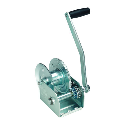
WINCH: manually operate component use to lift the cut pieces;
SELF TAILER: component positione at the en of the winch that allows to maintain the
tension on the rope woun aroun the rum;
ROPE GUIDE (SX, DX): steel rope gui e to irect the ropes with the right angle on the
aluminium cylin er brake;
ROPE GUIDE HOOK (SX,DX, CENTRAL):it allows to eviate the ropes so that the
groun operator can choose the most secure position uring the lowering operations;
RIGGING: lifting or lowering operations of the cut pieces of timber with the ai of cylin er
brakes, ropes an pulleys;
BLOCKS: pulleys specifically esigne for rigging operations uring controlle felling;
TREECLIMBER or elevating work platform operator (EWP) both must have a equate
training an qualification;
SLING : rope-length with a loop at one en an which normally hol s a Block or a
connector or a ring;
LOWERING: the controlle escent of a cut piece of tree;
STOPPER: component for the temporary locking of a rope; the stopper can be opene an
close with the rope pulle tight (but not moving) ;
GROUND OPERATOR: the person on the groun who controls the ropes uring the
controlle felling - rigging;
The groun operator must have a equate training.

ATD ArboTeamDevice
6
2. What is the ATD
2.1.Description
ATD is a specific tool to be use only for tree care operations, for lifting or lowering tree
sections uring controlle felling (rigging) or pruning (eg. removal of large ea or
amage branches).
ATD consists of a metal frame which acts as a support to a winch, wrappe by a aluminium
cylin er brake, a mechanical safety blocking system (stopper) an two straps (for anchoring
an positioning) .
Since the ATD is not the only equipment use uring the rigging, it is necessary that all the
other components (ropes, blocks, pulleys, slings, straps, connectors, etc) are in goo
con ition of use, properly size for the work to be performe an compatible with each
other.
All operating instructions must be observe , those in icate in this manual as well as those
provi e with each evice combine to the ATD .
Caution:
The activities involving the use of the ATD are inherently angerous.
Who uses the ATD is responsible for his/her own actions, ecisions an safety.
It is man atory to follow the current safety stan ar s.
Before using the ATD you must:
•rea an un erstan all operating instructions escribe in this manual;
•be properly traine for controlle felling with the use of aluminium cylin er brakes an
winches
•Un erstan an accept the risks involve

ATD ArboTeamDevice
7
Caution:
Failure to un erstan any part of this manual can result in serious or fatal acci ents.
The rea ing an un erstan ing of the ATD user's manual oes not replace in any way the
learning an training for controlle tree felling with the use of winches an aluminium
cylin er brakes.
While using ATD it is compulsory to always wear the following PPE :
1. protective helmet with visor or glasses;
2.heavy- uty gloves (leather recommen e )
3. antislip safety shoes with toecaps
When using the ATD, it is also necessary that operators :
•be in goo physical an mental con ition,
•wear tight clothing an no accessories which they coul get entangle with.
2.2. Technical data
2.2.1.Components
1) Steel frame
2) Winch 46.2 STGNP HARKEN® bran (MWL 1300 Kg) with self tailer
3) Aluminium cylin er brake
4) Screw pin for the use of two ifferent ropes
5) Left rope gui e
5A) Right rope gui e
6) Left rope gui e hook
6a) Right rope gui e hook
6b) Central rope gui e hook
7) 75 mm strap tension ratchet (Fig. 1.3.)

ATD ArboTeamDevice
8
7a) Crank bushing for the tension ratchet (Fig.1.3.)
7b) Protection for the 75mm strap (Fig.1.3.)
8) Fixing pin for the 75 mm strap
8a) Safety linch pins
9) 75 mm strap
9a) 25 mm strap
10) Mechanical safety blocking system stopper V Grip maxi Plus Antal
11)Stopper anchor plate
12) Fixing pin for the stopper
13) Fastening hinges for the DX stopper anchor plate
13a) Fastening hinges for the SX stopper anchor plate
14) Stopper's rope gui e
14a) Stopper's rope gui e
15)Anchorage for the 25 mm strap
16) Fixing point for winch han le
17) Winch han le
18) Slot for the 75 mm strap (Figure 2)
19) Removable rubber bark-saver protections(Figure 4)

ATD ArboTeamDevice
9
2
4
1
3
7
4
8
8a
6a
5a
5
6
6b
9
10
11
12
9a
14
14a
15
13
13a
7a
7b
Fig
ure
1
16
17

ATD ArboTeamDevice
10
Figure 2
2.2.2- Technical features
All the equipment, including the aluminium cylinder brake, the stopper, the
winch, the strap with relative tensions, etc .. , has been verified to the stresses
to which it is normally exposed during use. The calculations are part of the
technical file of the "machine ".
Total weight : 30,3 Kg
Weight of the stopper: 4,70 Kg
Maximum working loa of the aluminium cylin er brake : 2000Kg
Maximum working loa of the winch : 1300 Kg
7
7a
7b
18

ATD ArboTeamDevice
11
Maximum working loa of the stopper : 1300 Kg (with 16 mm plate)
Breaking loa of the yellow 75 mm strap : 15000 Kg
Breaking loa of the orange 25 mm strap : 400 Kg
3 - ATD application areas
ATD is an exclusive an specific tool to be use only for tree care operations, for lifting or
lowering branches an tree sections uring controlle felling (rigging) or pruning (eg.
removal of branches)
Caution:
It is absolutely forbidden to use ATD for lifting and lowering persons.
The ATD must not be stresse beyon the limits specifie in the manual in section 2.2.2
3.1- Combining with rigging ropes
ATD may be use only with the specific arborist ropes for controlle felling. The
characteristics of the ropes to be use with ATD are given In the technical ossier.
Caution :
It is forbi en to use any other cables inclu ing metal wire ropes.
3.2 Combining ropes with winch and stopper
Allowe Rope iameters must be between 14 mm an 16 mm ( ouble brai )
3.3 Combining ropes and aluminium cylinder brake
Allowed Rope iameters : 12 mm – 14 mm – 16 mm or 19 mm

ATD ArboTeamDevice
12
Caution :
Before every lifting or lowering operation it is necessary to :
•choose the rope correctly size for the task you want to perform
•check the ropes' con ition
•Define the anger zone an make sure that nobo y stays within it
4. Installation
There are two possible options for installation:
Hard installation, recommen e for tree felling
Soft installation, to be use mainly when pruning (without amaging the bark of the
tree that houses the ATD) by installing rubber protectors as shown in figure 3
Figure 3
19

ATD ArboTeamDevice
13
Caution :
Even before installing the ATD, it is necessary to perform a thorough inspection of the tree
in or er to i entify any structural efects that coul compromise the safety of the tree
felling or pruning (internal cavities, woo egra e by fungal attacks, cracks, amage to
root system, etc).
The surface of the tree where the straps an the steel frame are meant to be put up must
be free of any object that coul affect the proper functioning of the ATD (i.e. climbing
plants, branches, objects, nails, etc)
If in oubt, o not procee with the installation until you have stu ie in epth the problem
.
Plan the tree climber's tasks so as to install the ATD creating a safety zone on the groun .
For safety zone un erstan the space which is not affecte by the lowering of the pieces,
where the groun operator can operate the ropes without having suspen e loa s above
himself, an having a full view of the climber's work an of the lan ing space.
Steep angles with the groun where the groun operator will work can eviate the rigging
rope in the hooks with the risk of it coming out.

ATD ArboTeamDevice
14
4.1 - Hard installation
Working loa for winch 1300 kg – 2000 kg for aluminium cylin er brake
A- procee making a horizontal cut approximately 3 cm long an 10mm eep (this usually
correspon s to the cut generate by a me ium powere chainsaw).
Avoi excessively eep cuts which besi es being useless coul compromise the mechanical
strength of the tree.
B- place the ATD inserting the steel stabilisation plate insi e the generate slot (figure 4).
Figure 4
C- The strap must pass in the slot present on the cylin er of the jack. (Figure 2, n. 18)
Tighten the yellow strap using the winch han le after the strap has been passe aroun
the tree trunk .The strap must be tightene so as to prevent it from sli ing on the cylin er
of the jack as shown in figure 5.

ATD ArboTeamDevice
15
Figure 5
Do not excee the pre-tensioning of the strap
It,s enough the force applie by one single person.
D- tighten the orange strap so as to maintain the ATD in the correct position (firmly against
the tree trunk an without any possibility of movement in any irection)
Caution :
The orange strap oes not replace in any way the use of the yellow strap.
The ATD can only be use with both straps installe an tightene correctly .
4.2 - Soft installation
Working loa for Winch 800Kg - escen ing brake 800 kg
The soft installation is chosen when the tree on which the ATD is installe must be
preserve : o not procee therefore with the horizontal cut.
Before installation procee to mount the rubber protections screwing them completely in
the appropriate spots (figure 3).
Procee by following the steps escribe in the B - C - D points of the har installation.

ATD ArboTeamDevice
16
Caution :
The orange strap oes not replace in any way the use of the yellow strap.
The ATD can only be use with both straps installe an tightene correctly .
5- Using the ATD
5.1- Before each use
Caution
A general check shoul be performe on:
•Frame:, verify the integrity of the steel frame (wel ing, operating of the ratchet,
integrity of the hooks, integrity of the fastening hinges for the stopper anchor plate an
the fixing pins ) an any burrs in the areas in contact with the ropes an straps to avoi
these getting amage
•aluminium cylinder brake:check the correct tightening of the screws fixing it to the
frame, an the absence of cracks or any burrs
•winch: besi es referring to the information in the user's manual of the winch, check the
correct tightening of the screws fixing it to the frame, an that there are no amage
components that coul amage the ropes
•stopper: check the tightening of the screws on the stopper's anchor plate an the goo
con ition of the junction pins, the absence of foreign bo ies insi e the cam, the mobility
of the clamping lever, an the locking effectiveness for the chosen rope
•straps : the straps must be intact, with no cuts or abrasions , an with a rea able
i entification label .

ATD ArboTeamDevice
17
•nameplate : the nameplate which allows to i entify the ATD must be intact an
rea able
During use, check the tension of the straps.
Never leave the ATD unatten e after installing it.
The rigging rope can be installe on the ATD as follows :
1) with the stopper installed
(man atory when using the winch),
the rope must pass insi e the stopper, within the rope gui e of the stopper's anchor plate
an within the two rope gui es below it as shown in figure 6
Figure 6
2) without the stopper installed
(rope lowere on the aluminium cylin er brake)
The two rope gui e hooks (left an right) are not to be use for re irecting the rope!
The rope must pass insi e the two rope gui es on entering the aluminium cylin er brake
an accor ing to the nee s, to the right or to the left (figure7)

ATD ArboTeamDevice
18
Figure 7
Caution
In both cases escribe above the rigging rope must be lowere from above an reach the
ATD below the most vertically possible. The stopper must be installe with a maximum total
range of 10 egrees as shown in figure 8 (5 egrees at right, 5 egrees at left an 5
frontwar s).
Figure 8
If the rope oes not fall vertically, it is imperative to re irect it the by making it pass
through a sling combine with a pulley or connector or a ring.(figure 9)
10°
10°

ATD ArboTeamDevice
19
Figure 9
5.2- Use of the winch
Caution
The winch must always be use combine with a stopper.
The winch must be operate by a single operator
LIFTING
Once the operator has tie up the section to be remove ,
The ground operator must:
A- Open the stopper by turning the lever up (figure 10)
B- Insert the rope coming from above insi e the stopper
-or insert the rope into the stopper before forwar ing it up to the tree climber
C- Recover any rope slack between the knot point above in the tree an the stopper
Table of contents