ARC MWMR-250 User manual

1
Issue Date: 5/2/2020
WIRELESS DIMMER
MINI WALL MODULE
MWMR-250
CONTENTS
1. Overview and features Page 2.
2. Diagrams Page 3.
3. Installation –Wiring Page 4.
4. Pairing / Un-pairing device Page 7.
5. Non-Dimmable / Trailing & Leading Edge setup Page 9.
6. Operation Page 11.
7. Specifications Page 13.

2
Issue Date: 5/2/2020
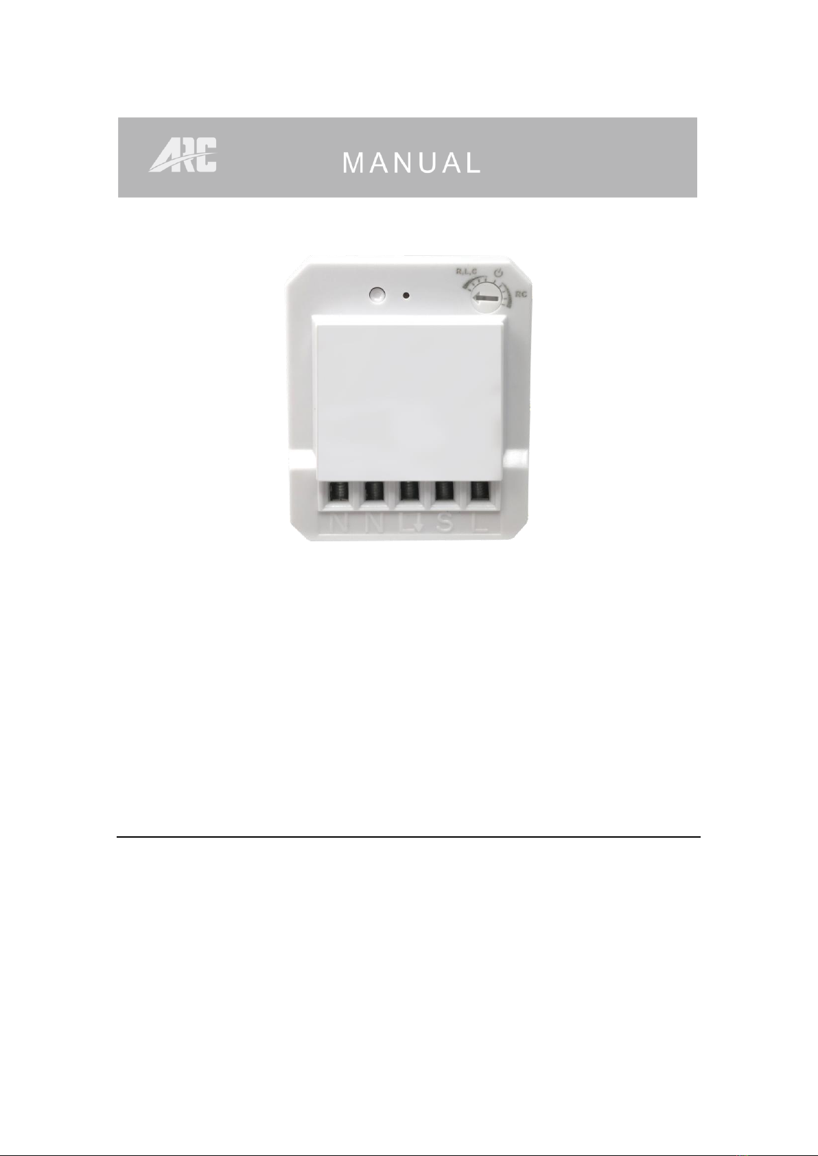
1.Overview and features
Remotely controlled 250W universal Mini Dimmer Wall Module is designed to
control existing dimmable LED, dimmable energy saving lamp, incandescent
lamp, 230V~ halogen lamp and 12V halogen lamp with inductive transformer or
electronic transformer.
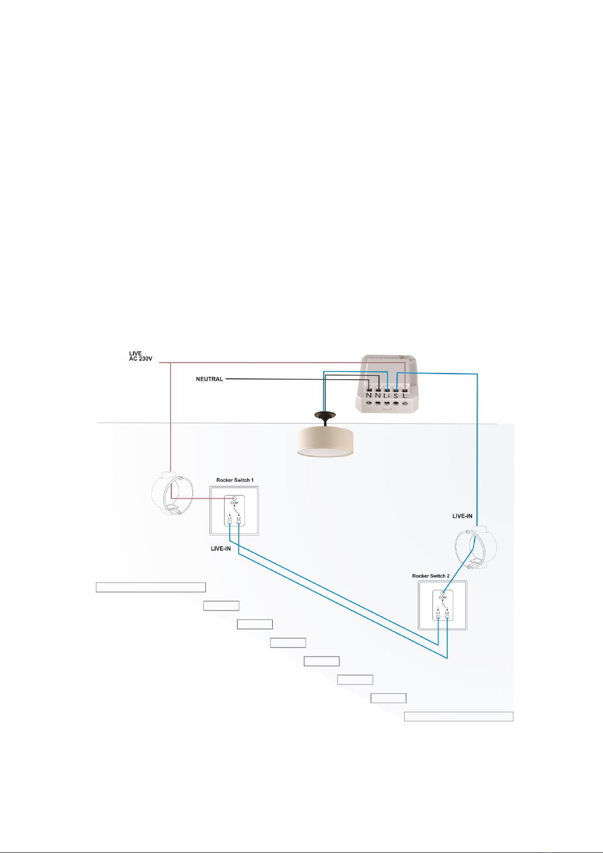
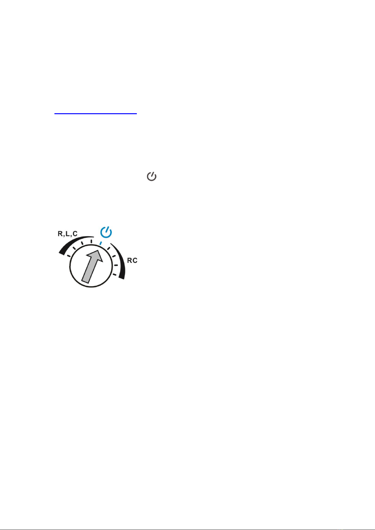
Especially designed for Rocker Switch control.
Main features of Mini Wall Module;
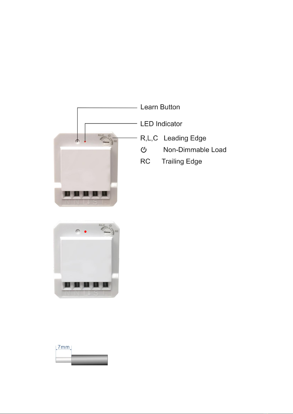
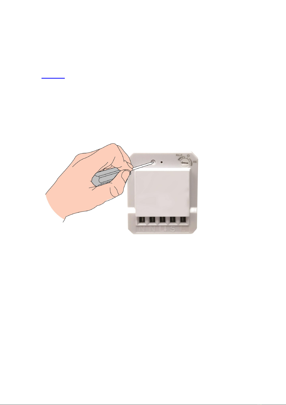
•Compatible to L and M series.
•Operating mode of Trailing Edge or Leading Edge.
•Ability to work with existing rocker switch for On / Off / Dimmer function.
•Minimum brightness setup for different kinds of dimmer loads.
•Small compact size for installation into wall box or inside light fittings
•32 memories, first in first out storage maintain.
•Memory of last brightness level.
•Scene status memory, create your desired atmosphere.
•2-way switch function.
Supported Load;
•230V operated conventional incandescent and halogen light source
•12V electronic transformers
•12V inductive transformers
•Dimmable and non-dimmable energy saving lamp
•Dimmable and non-dimmable LED
Not compatible to:
Fluorescent lamp
Momentary / push button switch
ARC Code switch system product range
OVERVIEW AND FEATURES

3
Issue Date: 5/2/2020
2.Diagrams
Notes for the diagrams:
N - Terminal for neutral wire
L- Output terminal for load wire
S - Terminal for power supply to the switch
L - Terminal for live wire
⚫Strip the solid wires (rigid conductor only) at least 7mm then connect the
wires as per diagrams below, ensure terminals are properly tightened and
no bare wire is visible.
⚫Suitable wire size for terminal is 1.6mm2 to 2mm2
DIAGRAMS

4
Issue Date: 5/2/2020
3.Installation - Wiring
Cut off main power before installing and wiring.
Current existing house wiring should be as below.
INSTALLATION - WIRING

5
Issue Date: 5/2/2020
Add mini module with one way operation
1. Connect permanent Live wire into module terminal ‘L’.
2. Connect Neutral wire into module terminal ‘N’.
3. Connect wire from module terminal ‘ L& N’ to Load.
4. Connect switch Live wire from module terminal ‘S’ into switch ‘L1’ terminal.
5. Connect permanent Live wire into switch ‘Com’ terminal.
6. Connect back mains power supply.
INSTALLATION - WIRING

6
Issue Date: 5/2/2020
Add mini module with two way operation
Two Way Operation
1. Switch 1 and 2 must be connected together with wires into ‘L1 & L2’ terminal.
2. Connect permanent Live wire into module terminal ‘L’.
3. Connect Neutral wire into module terminal ‘N’.
4. Connect wire from module terminal ‘ L& N’ to Load.
5. Connect permanent Live wire into switch 1 ‘Com’ terminal.
6. Connect switch Live wire from module terminal ‘S’ into switch 2 ‘Com’
terminal.
7. Connect wire from module terminal ‘L& N’ to Load
8. Connect back mains power supply.
INSTALLATION - WIRING

7
Issue Date: 5/2/2020
4.Pairing / Un-pairing Device
PAIRING
Pairing using LEARNING MODE:
1. Press ‘Learn’ button once (LED on module will flash), this will enter learning
mode.
2. With a remote control press the ‘ON’ button; LED on module will flash to
confirm that the remote control is now paired.
NOTE: If no signal is received from a remote control within 12 seconds then the
module will automatically exit learning mode without pairing the device.
To exit learning mode manually, simply press the ‘Learn’ button again.
PAIRING / UN-PARING DEVICE

8
Issue Date: 5/2/2020
UN-PAIRING
Removing single Device:
1. Press ‘Learn’ once (LED on module will flash), this will enter learning mode.
2. With a remote control press the ‘OFF’ button intended to be un-paired; LED
on module will flash to confirm that the remote control is un-paired.
CLEARING ALL MEMORY
Removing all memory stored in the module.
1. On the module hold down the ‘Learn’ button for 6 seconds, LED on module
will flash.
2. Release button then press again, this will remove all memory stored in the
module.
PAIRING / UN-PARING DEVICE

9
Issue Date: 5/2/2020
5.Non-Dimmable / Trailing & Leading Edge Setup
Initial factory pre-set is at ‘Leading Edge’ Position
NON-DIMMABLE LOAD
On-Off Function for non dimmable load.
Benefit to change from dimmable to non dimmable load without changing the
module and operates normally for On-Off function.
⚫Adjust rotary switch to position, LED on module will quick flash to
confirm and connected load will light up at full brightness.
⚫This confirms the mini wall module is properly setup under On-Off Function.
NON-DIMMABLE / TRAILING & LEADING EDEGE SETUP

10
Issue Date: 5/2/2020
TRAILING EDGE /LEADING EDGE /MINIMUM BRIGHTNESS LEVEL
Adjust the rotary switch on the top light hand corner to select trailing or leading
edge by trimmer resistor.
Leading Edge
⚫Adjust rotary switch counterclockwise to the very end of R,L,C position,
LED on module will blink once to confirm the mini wall module is properly
setup under leading edge.
⚫Slowly turn clockwise to adjust the minimum brightness level. If load flickers
or turns OFF during operation, adjust counterclockwise one level up until
the load lights up and do not flicker. Please adjust to the most suitable dim
level that you desire.
⚫During ON/OFF operation LED on module will flash once.
Trailing Edge
⚫Adjust rotary switch clockwise to the very end of RC position, LED on
module will blink once to confirm the mini wall module is properly setup
under Trailing Edge.
⚫Slowly turn counterclockwise to adjust the minimum brightness level. If load
flickers or turns OFF during operation, adjust clockwise one level up until
the load lights up do not flicker. Please adjust to the most suitable dim level
that you desire.
⚫During ON/OFF operation LED on module will flash twice.
NON-DIMMABLE / TRAILING & LEADING EDEGE SETUP

11
Issue Date: 5/2/2020
6.Operation
Mini module is compatible to “Self Learning” system and M series remote
control. Please refer to the relevant user guide for detailed operation.
Operation via Rocker Switch:
Turn the load ON:
Toggle switch once to turn ON load.
Turn the load OFF:
Toggle switch once again to turn OFF load.
Dimming the load:
In each operation, first time dimming, load will dim up and stops at brightest
level. 2nd time dimming, load will dim down and stops at the lowest level.
1. Toggle switch once to turn ON load
2. Quickly toggle switch twice to start dimming.
3. At the desired brightness level quickly toggle switch twice to stop.
During dimming process when the load level reaches to the lowest or
brightest, to continue dimming quickly toggle switch twice then at the desired
brightness level quickly toggle switch twice to stop.
Operation example using in conjunction with a remote control and rocker switch.
If load is switched ON from the rocker switch then switch OFF via the remote
control.
The next time turning ON the load can either be:
(i) on the remote press the ON button
OR
(ii) on rocker switch toggle switch once.
OPERATION

12
Issue Date: 5/2/2020
Rocker Switch Two way operation:
Turn the load ON:
Toggle switch once to turn ON load.
Turn the load OFF:
Toggle switch once again to turn OFF load.
Operation example:
Switch 1 is located downstairs & Switch 2 is located upstairs.
While going up the stairs, toggle “Switch 1” once to turn ON the load, once you
reach upstairs toggle “Switch 2” once to turn OFF the load.
OPERATION

13
Issue Date: 5/2/2020
7.Specifications
Input Rating: 230V~50Hz
Output Rating:
Supported Load
Wattage
“Trailing edge” for resistive loads (R)
•Conventional incandescent and halogen light
source
20-250W / 230V~
“Trailing edge” for resistive-capacitive loads (RC)
•Electronic transformers
•Dimmable LED and energy saving lamps.
20-250W / 230V~
3-120W / 230V~
“Leading edge” for resistive-inductive loads (RL)
•Inductive transformers
40-250W / 230V~
Radio Frequency: 433.92MHz
Power consumption: 1W
Environment Temperature: 0-40 ºC
Range: up to 50 m indoors (Depends on building
materials)
In accordance with: Low Voltage Directive 2014/35/EU
RED Directive 2014/53/EU
CE Certification: The CE marked affixed to this product confirms
Its complaisance with the European Directives
Which apply to the product and in particular its
compliance with the harmonizes standards and
specifications.
SPECIFICATION

14
Issue Date: 5/2/2020
Dimension (L x W x H) 45 x 40 x 15.2mm
Weight: 20 g
NOTE
⚫Please leave minimum of 1.5 meters in-between 2 or more modules.
⚫When inserting module into back box make sure excess wires do not cover
module’s back side. This may reduce the performance of radio
transmission.
⚫During standby mode, LED on module will not illuminate.
SPECIFICATION
Table of contents
Other ARC Dimmer manuals