Niko 05-707 User manual

nv Niko sa Industriepark West 40, BE-9100 Sint-Niklaas, Belgium — tel. +32 3 760 14 70 — fax +32 3 777 71 20 — e-mail: [email protected] — www.niko.be PM005-70700R07154
05-707
Proficiat met uw aankoop van dit product uit het dimmergamma van
Niko.
1. WETTELIJKE WAARSCHUWINGEN
- Lees de volledige handleiding vóór installatie en ingebruikname.
- De installatie dient te worden uitgevoerd door een bevoegd persoon en
met inachtname van de geldende voorschriften.
- Deze handleiding dient aan de gebruiker te worden overhandigd. Zij moet
bij het dossier van de elektrische installatie worden gevoegd en dient
te worden overgedragen aan eventuele nieuwe eigenaars. Bijkomende
exemplaren zijn verkrijgbaar via de Niko-website of -supportdienst.
- Bij de installatie dient rekening gehouden te worden met (lijst is niet
limitatief):
- de geldende wetten, normen en reglementen;
- de stand van de techniek op het ogenblik van de installatie;
- het feit dat een handleiding alleen algemene bepalingen vermeldt en dient
gelezen te worden binnen het kader van elke specifieke installatie;
- de regels van goed vakmanschap.
- Bij twijfel kan u de supportdienst van Niko raadplegen of contact opnemen
met een erkend controleorganisme.
Support België: Support Nederland:
tel. + 32 3 760 14 82 tel. + 31 183 64 06 60
website: http://www.niko.be website: http://www.niko.nl
In geval van defect kan u uw product terugbezorgen aan een erkende
Niko-groothandel samen met een duidelijke omschrijving van uw klacht
(manier van gebruik, vastgestelde afwijking…).
2. BESCHRIJVING
Intensiteitsregeling (dimming) van alle dimbare belastingen behalve flu-
orescentielampen.
Resistieve belastingen: gloeilampen, 230V halogeenlampen...
Inductieve belastingen: ferromagnetische transformatoren
Capacitieve belastingen: elektronische transformatoren...
3. WERKING EN GEBRUIK
Deze dimmer (05-707) werkt met vermogentransistoren i.p.v. triacs. Op die
manier kan zowel in faseaansnijding als faseafsnijding geschakeld worden.
Bij faseaansnijding wordt de dimmer uitgeschakeld bij de nuldoorgang en
voordien ingeschakeld. Deze schakeltechniek is aangewezen bij inductieve
belastingen (ferromagnetische transformatoren). Bij faseafsnijding wordt de
dimmer ingeschakeld bij de nuldoorgang en nadien uitgeschakeld. Deze
schakeltechniek is aangewezen bij:
- capacitieve belastingen (elektronische transformatoren dimbaar via
230V)
- resistieve belastingen
- gemengde belastingen (bovenvermelde + inductieve belastingen) aan-
gesloten op dezelfde dimmer.
Doordat de ontstoring volledig elektronisch is en er geen spoelen gebruikt
worden, zijn deze dimmers totaal geruisloos en tot 30% lichter dan de
klassieke dimmers.
De gebruikte technologie laat toe de dimmer elektronisch te beveiligen
tegen kortsluiting, overstroom en overspanning.
Deze dimmer wordt op afstand gestuurd via een analoog signaal of via
potentiaalvrije N.O.-contacten (bv. 07-000). De sturing is galvanisch van
het net gescheiden. Zowel de analoge als de druktoetsbedrading gebeurt
onder zeer lage spanning. Een lamp die aangesloten is via dimmers kan
niet tot de max. lichtintensiteit gedimd worden. De lichtopbrengst zal
steeds kleiner zijn dan die van een identieke lamp die rechtstreeks op
het net aangesloten is.
3.1 Analoge sturing (bv. via Nikobus 05-007-02)
Deze dimmer (05-707) kan met om het even welk toestel dat beantwoordt
aan de internationale standaard 0-10V (spanningssturing) of de 1-10V
(stroomsturing) op afstand bestuurd worden. De werking gebeurt analoog
(0V = uit, 10V = max. uitsturing). Analoge sturing en signaalkabels worden
via de dimmer galvanisch van het net gescheiden. De bedrading wordt
uitgevoerd in ZLS (zeer lage spanning).
3.2 Druktoetsbediening
Om het even welk potentiaalvrij N.O.-contact kan de dimmer bedienen. Kort
drukken voor aan/uit, lang drukken voor opdimmen/neerdimmen (fig. 1 & 2).
De druktoetsen worden via de dimmer galvanisch van het net gescheiden.
De bedrading wordt uitgevoerd in ZLS (zeer lage spanning).
3.3 Waarschuwingen bij gebruik
- Deze toestellen zijn niet geschikt voor het regelen van motoren, tenzij
de specifieke veiligheidseisen door externe systemen gewaarborgd
worden (automatisch herstarten na netonderbreking is in dit geval niet
toegelaten).
- Dit toestel is uitsluitend geschikt voor DIN-rail montage en moet in een
gesloten verdeelkast geplaatst worden.
- Dit toestel mag enkel onder spanning geplaatst worden na montage van
de nodige afdekkingen in de verdeelkast.
4. INSTELLINGEN DIP-SWITCHES
Nummer ON OFF
1 faseAANsnijding faseAFsnijding
2 druktoetsbediening analoog signaal
3 0-10V-spanningsturing 1-10V-stroomsturing
4 automatische selectie manuele selectie
Gemengde belastingen dimmen en de dimmer opstarten
Een gemengde belasting bestaat uit gewikkelde transformatoren (inductieve
lasten) en elektronische transformatoren (capacitieve lasten) die aange-
sloten zijn op éénzelfde dimmer. Lampen zonder voorschakelapparaat
(bv. gloeilampen) zijn resistief en vormen een neutrale belasting. Indien
de belasting niet gemengd is, zie 4.1 en 4.2.
Opgelet: bij gemengde belasting moet de dimmer ingesteld worden
in faseafsnijding. Gemengde belastingen mogen niet gedimd worden
in faseaansnijding. Indien de overspanningbeveiliging actief wordt in
faseafsnijding (rode LED nr. 4 licht op), moet de inductie gecompenseerd
worden. Inducties van gewikkelde transformatoren worden gecompenseerd
op dezelfde manier als ballasten van fluorescentielampen: plaats een
condensator van categorie X-2 tussen fase en neuter aan de primaire
zijde van de transformator. Waarde: ± 1µF per 50VA.
Volg onderstaande procedure als u twijfelt over het type belasting.
Stel de dimmer in voor faseafsnijding (dimmen van elektronische trans-
formatoren en/of resistieve lasten) door DIP-switch 1 in de OFF-stand te
zetten (4.2). Als er geen rode LED’s oplichten, betekent dit dat de belasting
overwegend capacitief is en dat de instelling juist is.
Als één of meerdere rode LED’s oplichten en/of de dimmer niet werkt (dim-
mer in beveiliging), betekent dit dat de belasting overwegend inductief is.
Wijzig in dit geval de stand van DIP-switch 1 naar ON (= faseaansnijding
voor inductieve belastingen, 4.1). Druk op de reset-knop of regel het
analoog signaal naar 0V om de dimmer te herstarten. Resistieve lasten
zijn neutraal en moeten in faseafsnijding gedimd worden.
4.1 Faseaansnijding: DIP-switch 1 instellen op ON
In deze mode kunnen enkel inductieve lasten (gewikkelde transformatoren)
gedimd worden. Alle andere belastingen, incl. resistieve lasten, moeten in
faseafsnijding gedimd worden (4.2). Bij selectie van deze mode licht de
gele LED 1 op ter controle (5.1).
4.2 Faseafsnijding: DIP-switch 1 instellen op OFF
In deze mode kunnen enkel resistieve en capacitieve lasten gedimd worden.
Deze mogen gemengd worden. Sluit nooit enkel inductieve lasten aan in
deze mode (4.1). Gebruik ook deze mode voor gemengde belastingen
(inductief + capacitief).
Opgelet: elektronische transformatoren van meer dan 105VA zijn niet
geschikt voor dimming. Deze transformatoren kunnen zorgen voor onstabiel
licht (knipperen). Als de belasting enkel capacitief is, moet de dimmer min.
belast worden door:
- 2 of meerdere elektronische transformatoren;
- of 1 elektronische transformator + 1 elektronische voorbelasting
(09-016-10).
Zet de dimmer in deze mode als u twijfelt over het type belasting.
4.3 Druktoetsbediening: DIP-switch 2 instellen op ON
Deze instelling laat bediening via N.O.-contacten toe. Een korte druk voor
inschakelen/uitschakelen. Een lange druk voor opdimmen/neerdimmen. Bij
lang drukken wordt na elke onderbreking de richting omgekeerd (opdimmen
-> stop -> neerdimmen -> stop -> opdimmen -> ...). Het laatste niveau
wordt al dan niet in een geheugen opgeslagen (4.9).
4.4 Analoge sturingen: DIP-switch 2 instellen op OFF
Deze instelling laat toe de dimmer via analoge stuursignalen te sturen (4.8).
4.5 Automatische selectie van het type stuursignaal (0-10 of 1-10V):
DIP-switch 4 instellen op ON
In deze stand zal de dimmer het type stuursignaal automatisch onderschei-
den en zelf de instelling kiezen (in tegenstelling tot de manuele instelling
beschreven in 4.6). Deze instelling gebeurt enkel bij het inschakelen van de
voeding. Voorwaarden voor gebruik van de automatische selectie:
Gebruik enkel de manuele instelling als meerdere dimmers met dezelfde
stuuruitgang verbonden zijn. Het gebruik van verschillende types dimmers
kan de detectie storen. Als dimmers 05-707 verdeeld zijn over verschillende
zekeringen, moeten alle zekeringen binnen 10s. ingeschakeld worden om
storing van de detectie te vermijden.
4.6 Manuele instelling van het stuursignaal: DIP-switch 4 inge-
steld op OFF
In deze stand wordt het type stuursignaal (0-10 of 1-10V) manueel bepaald
door de instelling van DIP-switch 3 (4.7 en 4.8).
4.7 Manuele instelling van het stuursignaal op 0-10V: DIP-switch
3 ingesteld op ON
Om deze functie te kunnen gebruiken moet:
- DIP-switch 4 eerst op OFF ingesteld worden (manuele instelling van het
stuursignaal: zie 4.6.)
- de DIP-switch 2 op OFF ingesteld staan (analoge sturing).
Bij selectie van deze mode licht de gele LED 2 op ter controle. In deze positie
zal de dimmer een spanningsstuursignaal van 0 tot 10V aanvaarden volgens de
IEC 61131-2 norm. Van 0 tot 10V is lichtregeling mogelijk van 0,1% tot max.
Bij 1V wordt de dimmer uitgeschakeld (functioneert als solid-state relais).
4.8 Manuele instelling van het stuursignaal op 1-10V: DIP-switch
3 ingesteld op OFF
Om deze functie te kunnen gebruiken moet:
- DIP-switch 4 eerst op OFF ingesteld worden (manuele instelling van het
stuursignaal: zie 4.6).
- DIP-switch 2 op OFF ingesteld staan (analoge sturing).
In deze positie werkt de dimmer via een stroomstuursignaal van 1 tot 10V
volgens de EN60929-norm (zie ook 4.7). Van 0 tot 1V is er geen lichtregeling.
Van 1 tot 10V is lichtregeling mogelijk van 0,1% tot max. Bij 1V wordt de
dimmer uitgeschakeld (functioneert als solid-state relais).
4.9 Druktoetsbediening met geheugen: DIP-switch 4 instellen op ON.
Als de dimmer via een druktoets bediend wordt (4.3), kan u kiezen voor de
werking met geheugen (DIP-switch 4 ON) of zonder geheugen (DIP-switch
4 OFF). Zonder geheugen schakelt de dimmer in op max. Met geheugen
schakelt de dimmer in op de laatst ingestelde waarde. Na inschakeling
van de voedingsspannning schakelt de dimmer in op 20%.
5. BEDRIJFS- EN FOUTCONTROLE MET BEHULP VAN LED’S
Deze dimmer is voorzien van een visuele controlefunctie door middel van 4
LED’s die na installatie zichtbaar blijven aan de voorkant van de dimmer.
Van links naar rechts (fig.4):
5.1 Aanduiding van werking in faseaansnijding:
LED 1 licht op (geel)
Symbool inductieve belasting boven LED 1. Deze LED licht op bij instelling
van DIP-switch 1 op stand ON.
5.2 Aanduiding selectie stuursignaal in spanningsturing:
LED 2 licht op (geel)
Symbool geregelde voeding boven LED 2. Deze LED licht op bij instelling
van DIP-switch 3 op stand ON en DIP-switches 4 en 2 op stand OFF.
5.3.1 Overstroom:
LED 3 licht op (rood)
Symbool I boven LED 3 en vermelding ‘overcurrent’ links van LED 3.
Deze beveiliging wordt ingeschakeld als
- de dimmer overbelast is;
- een kortsluiting aanwezig is in de belastingskring.
Als de rode LED oplicht, is de beveiliging in werking getreden. Dit kan
gebeuren in geval van inschakelpieken of kortsluiting.
In geval van kortsluiting zal de dimmer automatisch uitgeschakeld worden.
Nota: alle beveiligingssystemen zijn actief bij het inschakelen van de
netvoeding. Gedurende enkele seconden worden ze 1 na 1 uitgeschakeld.
De dimmer reageert niet op het signaal van de afstandsbediening zolang
deze controle niet succesvol beëindigd is.
Nadat de fout verholpen werd, kan de dimmer als volgt heringeschakeld
worden:
- druk op de reset-knop;
- regel het stuursignaal naar min. niveau (0 resp. 1V).
Opgelet: deze beveiliging is geen beveiliging voor personen. Een externe
beveiliging (automatische zekering) moet steeds voorzien worden.
5.3.2 Eerste thermische beveiliging:
LED 3 knippert (rood)
Als de temperatuur van het koelvlak 105°C overschrijdt, wordt deze
beveiliging geactiveerd en:
- knippert de derde LED (rood);
- wordt het vermogen van de dimmer beperkt tot 20% (het licht is regelbaar
tot max. 20%).
Zodra de temperatuur gedaald is, dooft de LED en is de dimmer weer
normaal regelbaar.
5.4 Overspanningsbeveiliging:
LED 4 licht op (rood)
Overspanningsbeveiliging (symbool U boven LED 4 en vermelding ‘over-
voltage’ links van LED 4).
Deze beveiliging wordt ingeschakeld als een overspanning (hoger dan
480V gedurende meer dan 100µs.) optreedt. Een overspanning kan
meerdere oorzaken hebben:
- al dan niet tijdelijke storing op het 230V-net;
- magnetische transformator met een te hoge inductie te wijten aan bv.
onvoldoende belasting (min. belasting van magnetische transformatoren
75%);
- magnetische transformator met verandering in de belasting (defecte
lampen niet tijdig vervangen);
- de dimmer is niet ingesteld in de juiste mode, bv. dimmen van inductieve
belastingen in faseafsnijding i.p.v. faseaansnijding (zie 3).
Indien de beveiliging optreedt, wijst dit op een abnormale situatie. Indien
de dimmer in beveiliging blijft, moet de fout opgezocht en verbeterd
worden.
Nadat de fout verholpen werd, kan de dimmer op volgende wijze herin-
geschakeld worden:
- druk op de reset-knop;
- of regel het stuursignaal naar het minimumniveau (respectievelijk 0 of
1V).
5.5 Aanduiding gelijkstroombeveiliging of thermische beveiliging:
LED's 3 + 4 lichten op
Aanduiding gelijkstroombeveiliging of thermische beveiliging.
5.5.1 Gelijkstroombeveiliging
Als een assymetrie van meer dan 1,5V gemeten wordt, zal de dimmer in
beveiliging gaan. Dit is vooral belangrijk voor het dimmen van inductieve
belastingen. Indien de dimmer per vergissing in faseafsnijdingsmode
inductieve belastingen dimt, zal deze beveiliging in werking treden. Een te
hoge assymetrie zorgt voor gebrom, opwarming en tenslotte verbranding
van transformatoren en lampen.
5.5.2 Tweede thermische beveiliging
De tweede thermische beveiliging is zelfherstellend. Bij oververhitting
wordt het toestel uitgeschakeld vanaf 115 °C op het koelvlak. Zolang
de thermische beveiliging ingeschakeld is, zal de dimmer niet reageren
op het stuursignaal. Als de temperatuur terug gedaald is, schakelt de
dimmer terug in.
6. NETAANSLUITINGEN
6.1 bovenaan van links naar rechts
L: 230V fase (voeding)
N: 230V neuter (voeding)
N: 230V neuter (belasting) intern doorverbonden
: geregelde fase (belasting)
De neuter van de belasting moet met de dimmer verbonden worden. Indien
de neuter rechtstreeks met het net verbonden wordt, is de werking van de
dimmer niet gegarandeerd.
Opgelet: voor het inschakelen controleren of alle verbindingen goed aan-
gespannen zijn. Bij onderhoud van de installatie moet men de spanning
op de klemmen nazien.
6.2 Sturingsaansluitingen: analoog signaal
Sturing met analoog signaal (onderaan):
'-' klem: massa van het stuursignaal (0V)
'+' klem: stuursignaal: analoge regeling van 0 of 1 tot 10V
Opgelet: dezelfde klemmen worden zowel gebruikt voor 0-10V-span-
ningsturing als 1-10V-stroomsturing en druktoetsbediening. De polariteit
dient gerespecteerd te worden. Bij doorverbinding van meerdere dimmers
aan eenzelfde stuuruitgang nooit de '-' en '+' verwisselen.
De stuuringang is galvanisch gescheiden. De isolatie binnen de dimmer
staat borg voor een sturing in zeer lage spanning.
De 1-10V-stroomsturing is beschreven in de Europese standaard EN60929.

nv Niko sa Industriepark West 40, BE-9100 Sint-Niklaas, Belgium — tel. +32 3 760 14 70 — fax +32 3 777 71 20 — e-mail: [email protected] — www.niko.be PM005-70700R07154
05-707
Drukknopbediening 05-707
Met geheugen: DIP-switch 2 op ON
DIP-switch 4 op ON
kort drukken (<0,4s.) = ON / OFF
lang drukken (>0,4s.) = UP / DOWN
Bij stijgen: stop op 100%
Bij dalen, stop 2s. op min., daarna stijgen.
Herhaaldelijk drukken keert de dimrichting om.
ON /OFF
UP / DOWN
0%
min.
100%
I
0
2s.
4s.
Deze stuurtechniek wordt hoofdzakelijk gebruikt voor het sturen van EVSA
(elektronische voorschakelapparaten) d.m.v. zogenaamde elektronische
potentiometer bv. 09-011. De intensiteit van de stroom die door de stuurkring
vloeit, bepaalt het lichtniveau. Deze zogenaamde 'current sink' stuursig-
nalen zijn fundamenteel verschillend van de 0-10V-stuursignalen die als
'source'-signalen bekend zijn. De 0-10V spanning- of 'source'-signalen
worden typisch gebruikt in professionele toepassingen zoals: PLC’s, Silicon
Controls-stuursystemen of de Nikobus-dimcontroller 05-007-02.
6.3 Sturingsaansluitingen: druktoetsbediening
Sturing met N.O.-contacten (onderaan):
'-' klem: gemeenschappelijk voor alle contacten
'+' klem: signaal
De druktoetsen mogen in geen geval met het net verbonden worden.
7. TEST
De dimmer kan permanent op maximum werken door een simpele in-
greep:
- 230V-voeding dubbelpolig onderbreken;
- zet de DIP-switch nr. 4 in de stand OFF (manuele keuze);
- zet de DIP-switch nr. 2 in de stand OFF (analoge sturing);
- zet de DIP-switch nr. 3 in de stand OFF (1-10V);
- koppel de beide 10V-stuurdraden los;
- schakel de 230V-voeding in;
De dimmer schakelt nu op maximum zonder dat een stuursignaal nodig
is.
Waarschuwing: de dimmers worden nooit door een bediening van de
sturing elektrisch van het net gescheiden. Alle delen, inclusief de lampen,
blijven dus onder spanning ook al is het licht 'uit'.
Signalen die via het net gestuurd worden, kunnen de werking van de
dimmer storen. De storing treedt alleen op als dit signaal over het net
gestuurd wordt.
8. KOELING
De koeling is essentieel voor een bedrijfszeker en veilig gebruik.
De dimmer produceert ongeveer 1,2% warmte t.o.v. het aangesloten
verbruik. Bv. 500W verlichting = 6W dissipatie
Zorg voor een aangepaste circulatie van koele lucht t.o.v. het totaal gedis-
sipeerd vermogen. Indien de natuurlijke luchtcirculatie beperkt is, moet er
een ventilator in de kast of in het lokaal voorzien worden.
Nominale omgevingstemperatuur: 20°C
9. ONTSTORING
Storing over de voedingskabels: de ontstoringsgraad beantwoordt aan de
Europese standaard (EN55015) en internationale normen (CISPR15).
10. TECHNISCHE GEGEVENS
voeding: 230V~ 50Hz
afmetingen: (H x B x D) 89 x 70 x 54,5mm
gewicht: 0,216kg
min.belasting: 35W of 2 elektronische transformatoren
max.belasting: zie vermogentabel (fig. 3)
Belangrijk: de max. belasting is hoofdzakelijk afhankelijk van de omge-
vingstemperatuur (fig. 3).
Bijzondere opmerking i.v.m. inductieve lasten:
- ferromagnetische (gewikkelde) transformatoren moeten voor min. 75%
belast zijn;
- het verbruik van ferromagnetische transformatoren moet met de cosinus
phi vermeerderd worden;
- bij gebruik van ringkerntransformatoren is de max. belasting beperkt
tot 450W.
11. ONDERHOUD
Deze toestellen zijn gemaakt voor gebruik in volgende omstandigheden:
- een omgevingstemperatuur van 35°C;
- een niet condenserende luchtvochtigheidsgraad;
- een netspanning van 230V.
Regelmatig nazicht van minimaal het volgende, is aangewezen na volledige
uitschakeling van de netvoeding:
- druk van de aansluitklemmen,
- ventilatie.
12. GARANTIEBEPALINGEN
- Garantietermijn: twee jaar vanaf leveringsdatum. Als leveringsdatum
geldt de factuurdatum van aankoop van het goed door de consument.
Indien geen factuur voorhanden is, geldt de productiedatum.
- De consument is verplicht Niko schriftelijk over het gebrek aan overeenstem-
ming te informeren, uiterlijk binnen de twee maanden na vaststelling.
- In geval van een gebrek aan overeenstemming van het goed heeft de
consument recht op een een kosteloze herstelling of vervanging, wat
door Niko bepaald wordt.
- Niko is niet verantwoordelijk voor een gebrek of schade als gevolg van
een foutieve installatie, oneigenlijk of onachtzaam gebruik of verkeerde
bediening of transformatie van het goed.
- De dwingende bepalingen van de nationale wetgevingen betreffende de
verkoop van consumptiegoederen en de bescherming van de consumenten
van de landen waarin Niko rechtstreeks of via zuster/dochtervennoot-
schappen, filialen, distributeurs, agenten of vaste vertegenwoordigers
verkoopt, hebben voorrang op bovenstaande bepalingen.
fig.1
fig.2
fig.3
fig.4
Drukknopbediening 05-707
Zonder geheugen: DIP-switch 2 op ON
DIP-switch 4 op OFF
kort drukken (<0,4s.) = ON / OFF
lang drukken (>0,4s.) = UP / DOWN
Bij stijgen: stop op 100%
Bij dalen, stop 2s. op min., daarna stijgen.
Herhaaldelijk drukken keert de dimrichting om.
0%
min.
100%
I
0
2s.
4s.
ON /OFF
UP / DOWN
600
500
400
300
200
100
10 20 30 40 50
MIN.
Belasting
MAX.
Belasting
°C
W
a
t
Omgevingstemperatuur
memo
35°C = 600W
40°C = 550W
45°C = 500W
50°C = 450W
ON
OFF
I U
0 - 10V
1234
HAL.12 - 24V
ON
OFF
I U
0 - 10V
1234
HAL.12 - 24V
Faseaansnijding (Inductief)
1 OFF = faseafsnijding (res. + cap.)
Overstroombeveiliging
(kortsluiting of overbelasting)
Overspanningsbeveiliging
(faseafsnijding i.p.v. -aansnijding of
defecte belasting of pieken op het net)
Gelijkstroom of thermische beveiliging
Manuele instelling van het
stuursignaal op 0/10V
3 OFF = analoog 1/10V
ON
OFF
1234
1 Faseafsnijding
2 Analoge sturing
3 Manuele instelling van het
stuursignaal op 1/10V
4 Manuele keuze van het
stuursignaal (0/10V of 1/10V)
ON
OFF
1234
Druktoetsbediening
2 OFF = analoge sturing
ON
OFF
1234
Druktoetsbediening
met geheugen
4 OFF = zonder geheugen
ON
OFF
1234
Automatische selectie van het
stuursignaal (0/10V of 1/10V)
4 OFF = manuele keuze

nv Niko sa Industriepark West 40, BE-9100 Sint-Niklaas, Belgium — tel. +32 3 760 14 70 — fax +32 3 777 71 20 — e-mail: [email protected] — www.niko.be PM005-70700R07154
05-707
Stap 1 (Instelling schakelprincipe) Voeding uitschakelen
➡
Alleen voeding en belasting verbinden
(geen afstandsbediening verbinden)
➡
Instellen op FaseAFsnijding
➡
Voeding inschakelen
➡
➡
➡
➡
➡
OK
➡
➡
➡
Resistieve lasten Overspanningsbeveiliging Overbelasting of kortsluiting Dimmer niet belast
Capacitieve lasten
➡
➡
➡
(elektronische transformatoren) Voeding Voeding Voeding
Gemengde belastingen uitschakelen uitschakelen uitschakelen
➡
➡
➡
➡
Ga naar stap 2 Instellen op faseAANsnijding Kortsluiting verwijderen Belasting aansluiten
of belasting verminderen
➡
➡
Voeding inschakelen
➡
Voeding inschakelen
Voeding inschakelen
➡
➡
➡
OK
➡
Inductieve lasten Overbelasting
(ferromagnetische
➡
transformatoren) Voeding
➡
uitschakelen
Ga naar stap 2 Belasting verminderen
➡
Voeding inschakelen
Stap 2 (Instelling afstandsbediening) Voeding uitschakelen
➡
Stuursignaal verbinden
➡
Keuze sturing
➡
➡
➡
Druktoetsbediening (zie 4.3) Analoge sturing (zie 3.1)
➡
➡
➡
➡
➡
➡
Zonder geheugen (zie 4.9) Met geheugen (zie 4.9) Automatische selectie (zie 4.5) Manuele keuze (zie 4.6)
➡
➡
➡
➡
Voeding inschakelen Voeding inschakelen Voeding inschakelen
➡
➡
➡
➡
➡
0-10V analoog 1-10V analoog
Druktoets kort indrukken Druktoets kort indrukken 10s. wachten (zie 4.7) (zie 4.8)
➡
➡
➡
Aandimmen naar max. lichtsterkte Aandimmen naar 20%
➡
➡
➡
➡
Kort drukken uit Lang drukken voor ⇑⇓ Voeding Voeding
➡
➡
inschakelen inschakelen
OK OK
➡
➡
Elektronische
➡
potentiometer
Sturing bedienen bedienen
➡
➡
➡
Dimmer volgt Dimmer volgt niet Dimmer volgt
➡
➡
➡
OK Voeding OK
uitschakelen
➡
'+' en '-' omdraaien
➡
Procedure herbeginnen
➡

nv Niko sa Industriepark West 40, BE-9100 Sint-Niklaas, Belgium — tel. +32 3 760 14 70 — fax +32 3 777 71 20 — e-mail: [email protected] — www.niko.be PM005-70700R07154
05-707
Nous vous félicitons pour l’achat de ce produit de la gamme de varia-
teurs Niko.
1. PRESCRIPTIONS LEGALES
- Lisez entièrement le mode d’emploi avant toute installation et mise en
service.
- L’installation doit être effectuée par une personne compétente et dans
le respect des prescriptions en vigueur.
- Ce mode d’emploi doit être remis à l’utilisateur. Il doit être joint au dossier
de l’installation électrique et être remis à d’éventuels autres propriétaires.
Des exemplaires supplémentaires peuvent être obtenus sur le site web
ou auprès du service ‘support Niko’.
- Il y a lieu de tenir compte des points suivants avant l’installation (liste
non limitative):
- les lois, normes et réglementations en vigueur;
- l’état de la technique au moment de l’installation;
- ce mode d’emploi qui doit être lu dans le cadre de toute installation
spécifique;
- les règles de l’art.
- En cas de doute, vous pouvez appeler le service ‘support Niko’ ou vous
adresser à un organisme de contrôle reconnu.
Support Belgique: Support France:
+ 32 3 760 14 82 + 33 4 78 66 66 20
site web: http://www.niko.be site web: http://www.niko.fr
En cas de défaut de votre appareil, vous pouvez le retourner à un grossiste
Niko agréé, accompagné d’une description détaillée de votre plainte
(manière d’utilisation, divergence constatée…).
2. DESCRIPTION
Régulation de l’intensité lumineuse (variation) de tout type de charges
variables, à l’exception de lampes fluorescentes.
Charges résistives: lampes à incandescence, lampes aux halogènes 230V...
Charges inductives: transformateurs ferromagnétiques (bobinés)
Charge capacitives: transformateurs électroniques…
3. FONCTIONNEMENT ET UTILISATION
Le variateur Niko 05-707 utilise des transistors de puissance au lieu de
triacs. Ceci permet le fonctionnement aussi bien en contrôle de phase
qu’en contrôle de phase inversé. Contrôle de phase: le semi-conducteur de
puissance est enclenché avant le passage à zéro du secteur et est débranché
au zéro du secteur. Ce mode de commutation est de rigueur pour les charges
inductives (transformateurs ferromagnétiques). Contrôle de phase inversé:
le semi-conducteur est enclenché au passage à zéro du secteur et ensuite
débranché. Ce mode de fonctionnement est de rigueur pour:
- charges capacitives (transformateurs électroniques variables via 230V);
- charges résistives;
- charges mixtes (charges ci-dessus + charges inductives) raccordées
sur un seul variateur
Vu le déparasitage électronique et l’absence de selfs de déparasitage, ces
variateurs ont un fonctionnement totalement silencieux et possèdent un
poids de 30% inférieur à celui de variateurs classiques. La technologie
utilisée autorise une protection électronique contre le court-circuit, la
surcharge et la surtension.
Ces variateurs sont commandés par un signal analogique ou par des contacts
libres de potentiel N.O. (p.ex. 07-000). La commande est isolée galvanique-
ment du secteur. Aussi bien la commande analogique que la commande
par bouton-poussoir sont effectuées en TBT (très basse tension).
Les lampes qui sont reliées à des variateurs ne peuvent pas être allumées
jusqu’à leur niveau de luminosité max. L’intensité lumineuse max. sera toujours
moins élevée que celle d’une lampe directement connectée au réseau.
3.1 Commande analogique (p.ex. via Nikobus 05-007-02)
Les variateurs Niko 05-007 peuvent être commandés par n’importe quel
appareil répondant à la norme internationale 0-10V (commande en tension)
ou 1-10V (commande en courant). Le fonctionnement est analogique
(0V= éteint, 10V= valeur de luminosité max.). La commande analogique
et les câbles signalétiques sont isolés galvaniquement du secteur par le
variateur. Le câblage est effectué en TBT.
3.2 Commande par bouton-poussoir
La commande se fait par n’importe quel contact libre de potentiel N.O.
Pression brève pour allumer/éteindre, pression soutenue pour augmenter/
diminuer (fig. 1 & 2). Les boutons-poussoirs sont isolés galvaniquement
du secteur par le variateur. Le câblage est effectué en TBT.
3.3 Avertissements lors de l’utilisation
- Cet appareil ne convient pas pour la régulation de vitesse de moteurs, sauf
si des systèmes externes garantissent les exigences de sécurité spécifiques
(redémarrer automatiquement après une coupure du courant n’est pas
autorisé dans ce cas).
- Cet appareil est conçu uniquement pour montage sur rail DIN et doit
être placé dans une armoire de distribution close.
- Ne mettez pas l’appareil sous tension, avant d’avoir monté les protections
nécessaires dans l’armoire de distribution.
4. REGLAGE DES COMMUTATEURS MINIATURES (DIP-SWITCH)
Numéro ON OFF
1 Contrôle de phase Contrôle de phase inversé
2 Commande par poussoir signal analogique
3 commande en tension
0-10V
commande en courant
1-10V
4 sélection automatique sélection manuelle
Variation d’éclairage pour charges mixtes et mise en service
du variateur
Une charge mixte est constituée de transformateurs ferromagnétiques
(charges inductives) et de transformateurs électroniques (charges ca-
pacitives) reliés à un même variateur. Des lampes sans ballast (p. ex.
lampes à incandescence) forment une charge résistive et sont considérées
comme charge ‘neutre’.
Si la charge n’est pas mixte, voir 4.1 et 4.2.
Attention: pour des charges mixtes, le variateur doit être placé en contrôle
de phase inversé. Les charges mixtes ne peuvent être régulées en contrôle
de phase. Il sera nécessaire de compenser l’induction des transformateurs
ferromagnétiques au cas où la protection en surtension est activée en
contrôle de phase inversé (LED rouge 4 s’allume). L’induction des trans-
formateurs ferromagnétiques est compensée de la même manière que
dans le cas de ballasts fluorescents: placez un condensateur de classe
X-2 entre la phase et le neutre du circuit primaire du transformateur.
Valeur: ± 1µF par 50VA.
Suivez la procédure suivante si vous doutez du type de charge.
Placez le variateur en mode de contrôle de phase inversé (variation de
transformateurs électroniques et/ou de charges résistives) en mettant le
DIP-switch 1 en position OFF (4.2).
Si aucune LED rouge ne s’allume, cela signifie que la charge est essentiel-
lement capacitive et que par conséquent le réglage effectué est correct.
Si, par contre, une ou plusieurs LED rouges s’allument, et/ou le variateur
ne fonctionne pas (variateur en sécurité), cela signifie que la charge est
essentiellement inductive. Changez alors la position du DIP-switch 1 vers
ON (= contrôle de phase pour charges inductives, 4.1).
Enfoncez le bouton de reset ou réglez le signal de commande sur 0V avant de
relancer le variateur. Les charges résistives sont considérées comme neutres
et doivent être régulées en position de contrôle de phase inversé.
4.1 Contrôle de phase: DIP-switch 1 réglé sur ON
Ce mode ne convient que pour les charges inductives (transformateurs
ferromagnétiques). La variation de tout autre type de charge doit s’ef-
fectuer en contrôle de phase inversé (4.2). Dans ce mode, la LED jaune
1 s’allume (5.1).
4.2 Contrôle de phase inversé: DIP-switch 1 réglé sur OFF
Ce mode ne convient que pour les charges résistives et capacitives. Elles
peuvent cependant être mixtes. N’utilisez jamais des charges inductives
seules ( 4.1) dans ce mode. Utilisez ce mode aussi pour des charges
mixtes (inductives + capacitives).
Attention: les transformateurs électroniques de plus de 105VA ne sont
pas destinés à une variation d’éclairage. Ils peuvent être responsables
d’une luminosité instable (clignotement). Si la charge est exclusivement
capacitive il y a lieu de prévoir une charge min. soit par:
- 2 ou plusieurs transformateurs électroniques
- 1 transformateur électronique + 1 précharge électronique (09-016-10).
Mettez le variateur dans cette position si vous doutez du type de la charge.
4.3 Commande par bouton-poussoir: DIP-switch 2 réglé sur ON
Cette position autorise la commande au moyen de contacts N.O. Une
pression brève pour allumer/éteindre et une pression soutenue pour
monter/descendre.
L’action est inversée après chaque interruption (monter -> arrêt -> des-
cendre -> arrêt -> monter -> etc.). Le dernier niveau lumineux peut être
mémorisé (4.9).
4.4 Commande analogique: DIP-switch 2 réglé sur OFF
Cette position autorise la commande du variateur au moyen d’une com-
mande analogique (4.8).
4.5 Sélection automatique du type de signal de commande (0-10V
ou 1-10V): DIP-switch 4 réglé sur ON
Dans cette position, le variateur reconnaîtra automatiquement le signal de
commande et choisira lui-même le mode adéquat (contrairement à une
sélection manuelle décrite au point 4.6). Ce choix ne s’effectue qu’à la mise
sous tension. Conditions pour la sélection automatique: utilisez uniquement
le mode manuel si plusieurs variateurs sont reliés à la même sortie de com-
mande. L’emploi de variateurs de types différents peut perturber la détection.
Si plusieurs variateurs type 05-707 sont répartis sur plusieurs disjoncteurs
de branchement, ceux-ci doivent être enclenchés dans les 10s. afin de ne
pas perturber la détection.
4.6 Sélection manuelle du signal de commande: DIP-switch 4
réglé sur OFF
Dans cette position, le type de signal de commande (0-10V ou 1-10V) est
défini manuellement par la position du DIP-switch 3 (4.7 et 4.8).
4.7 Sélection manuelle du signal de commande en 0-10V: DIP-
switch 3 réglé sur ON
L’utilisation de cette fonction nécessite:
- le DIP-switch 4 sur la position OFF (c.-à-d. sélection manuelle du signal
de commande, 4.6).
- le DIP-switch 2 en position OFF (commande analogique)
Dans ce mode, la LED de contrôle jaune 2 s’allume. Le variateur fonctionne
alors avec un signal de commande en tension de 0 à 10V selon la norme
IEC 61131-2. Pour une plage de 0 à 10V, nous obtenons une variation
d’éclairage de 0,1% à la valeur de luminosité max. A une tension de 1V,
le variateur est coupé (fonctionne comme relais statique).
4.8 Sélection manuelle du signal de commande en 1-10V: DIP-
switch 3 réglé sur OFF
L’utilisation de cette fonction nécessite:
- le DIP-switch 4 en position OFF (c.-à-d. sélection manuelle du signal de
commande, 4.6).
- le DIP-switch 2 en position OFF (commande analogique).
Le variateur fonctionne alors avec un signal de commande en courant de 1 à
10V selon les prescriptions de la norme EN60929 (voir aussi 4.7). De 0 à 1V,
aucune possibilité de variation d’éclairage. De 1 à 10V nous obtenons une
variation d’éclairage de 0,1% à la valeur de luminosité max. A une tension
de 1V, le variateur est coupé (fonctionne comme relais statique).
4.9 Commande par bouton-poussoir et mémorisation: DIP-switch
4 réglé sur ON.
Au cas où le variateur est commandé par bouton-poussoir (voir 4.3), vous
pouvez choisir de mémoriser le dernier niveau d’éclairage (DIP-switch 4
sur ON) ou non (DIP-switch 4 sur OFF). Sans mémorisation, le variateur
enclenche l’éclairage à la tension max. Avec mémorisation, le variateur
enclenche l’éclairage à la dernière valeur réglée. Le variateur se positionne
à 20% au branchement de l’alimentation.
5. DIAGNOSTIC DE FONCTIONNEMENT ET DE DEFAUT PAR LED
Le variateur 05-707 est pourvu d’une fonction visuelle de contrôle au
moyen de 4 LED sur l’avant du variateur.
De gauche à droite (fig.4):
5.1 Indication de fonctionnement en contrôle de phase:
LED 1 s’allume (jaune)
Symbole de charge inductive au-dessus de la LED 1. Cette LED s’allume
lorsque le DIP-switch 1 est mis en position ON.
5.2 Indication de la sélection du signal de commande en tension:
LED 2 s’allume (jaune)
Symbole d’alimentation régulée au-dessus de la LED 2. Cette LED s’allume
lorsque le DIP-switch 3 est mis en position ON et les dip-switches 4 et
2 en position OFF.
5.3.1 Surcharge:
LED 3 s’allume (rouge)
Indication de surcharge (symbole I au-dessus de la LED 3 avec indication
‘overcurrent’ à la gauche de la LED 3).
Cette protection entre en service lorsque:
- le variateur est surchargé;
- un court-circuit apparaît dans un circuit de puissance.
L’allumage de la LED rouge indique une mise en sécurité. Cette protection
peut intervenir dans le cas de pointes de courant lors de la mise en service
et de courts-circuits.
S’il y a court-circuit, le variateur sera automatiquement mis hors service.
Note: tous les systèmes de protection de l’appareil sont activés lors de
la mise sous tension. Ils sont ensuite désactivés les uns après les autres
au cours d’une procédure qui ne nécessite que quelques secondes. Le
variateur ne réagira d’ailleurs pas au signal de commande avant que
cette procédure ait réussi.
Après avoir éliminé le défaut, le variateur peut être réenclenché:
- soit en appuyant sur le bouton de reset;
- soit en abaissant le niveau du signal de commande jusqu’au seuil min.
(resp. 0 ou 1V).
Attention: cette protection n’est pas une protection de personnes. Prévoyez
toujours une protection externe (disjoncteur de branchement).
5.3.2 Première protection thermique:
LED 3 clignote (rouge)
Si la température de la surface de refroidissement dépasse 105°C, la
protection sera activée et:
- la LED 3 (rouge) clignote;
- la charge du variateur est réduite à 20% (variation d’éclairage jusqu’à
20% de luminosité).
Dès que la température s’abaisse, la LED s’éteint et le variateur peut
reprendre son fonctionnement normal.
5.4 Protection de surtension:
LED 4 s’allume (rouge)
Protection de surtension (symbole U au-dessus de la LED 4 et indication
‘overvoltage’ à la gauche de la LED 4).
Cette protection entre en service dès l’apparition d’une tension supérieure
à 480V pendant un temps supérieur à 100µs. Une surtension peut avoir
plusieurs causes, notamment:
- perturbations temporaires ou durables sur le réseau 230V;
- utilisation d’un transformateur magnétique à trop forte induction causée
p.ex. par une charge trop faible (la charge min. de transformateurs
magnétiques est de 75%);
- utilisation d’un transformateur magnétique présentant une charge variable
(remplacement trop tardif de lampes défectueuses);
- les DIP-switches du variateur ne se trouvent pas dans la bonne position,
p.ex. utilisation en contrôle de phase inversé pour une charge inductive
au lieu d’un contrôle de phase (voir 3).
Si l’appareil se met en protection, cela implique une situation anormale. Si
cette situation persiste, il y a lieu de rechercher le défaut et d’y remédier.
Après avoir éliminé un défaut, le variateur peut être réenclenché:
- soit en appuyant sur le bouton de reset;
- soit en abaissant le niveau du signal de commande jusqu’au seuil min.
(resp. 0 ou 1V).
5.5 Protection de fonctionnement en courant continu ou protection
thermique: LED 3 + 4 s’allument
Protection de fonctionnement en courant continu ou protection thermique.
5.5.1 Protection de fonctionnement en courant continu
La détection d’une asymétrie de plus de 1,5V met le variateur en sécurité.
Ceci est particulièrement indiqué dans le cas d’une variation d’éclairage de
charges inductives. La mise par inadvertance des dip-switches en position
de contrôle de phase inversé. Lors de variation de charges inductives
engendre la mise en sécurité du variateur. Une trop grande asymétrie
engendre vibrations et surchauffe et peut occasionner la détérioration du
transformateur et des lampes.
5.5.2 Deuxième protection thermique
La deuxième protection thermique est pourvue d’un réarmement automati-
que. Une surchauffe éventuelle coupe l’appareil à partir d’une température
de 115°C sur le refroidisseur. Tant que cette protection est enclenchée,
le variateur ne réagira pas au signal de commande. Si la température a
baissé, le variateur est réenclenché.
6. RACCORDEMENTS AU RESEAU
6.1 de gauche à droite sur la partie supérieure
L: phase 230V (alimentation)
N: neutre 230V (alimentation)
N: neutre 230V (charge) connecté sur le module au neutre de l’alimentation
: phase régulée (charge)
Le neutre de la charge doit être raccordé au variateur. Si le neutre est
raccordé directement au réseau, le bon fonctionnement du variateur n’est
pas garanti.

nv Niko sa Industriepark West 40, BE-9100 Sint-Niklaas, Belgium — tel. +32 3 760 14 70 — fax +32 3 777 71 20 — e-mail: [email protected] — www.niko.be PM005-70700R07154
05-707
Attention: avant la mise en marche, vérifiez le bon serrage des câbles.
Vérifiez celui-ci également lors d’un entretien régulier.
6.2 Raccordement du signal de commande: signal analogique
Commande avec signal analogique (partie inférieure)
borne ‘-‘: masse du signal de commande (0V)
borne ‘+’: signal de commande: régulation analogique de 0 ou de 1 à 10V.
Attention: ces bornes sont utilisées pour les systèmes 0-10V, 1-10V ou la commande
par bouton-poussoir. Respectez la polarité. Ne jamais intervertir le ‘-‘ et le ‘+’ lors du
fonctionnement de plusieurs variateurs sur un même signal de commande. L’entrée
du signal de commande est séparée galvaniquement du réseau. L’isolation interne du
variateur est garante du fonctionnement de la commande en TBT.
La commande avec signal en courant de 1-10V est décrite dans la norme européenne
EN60929. Cette technique de commande est principalement utilisée pour la commande
de ballasts électroniques réglables (BER) au moyen d’un potentiomètre électronique
p.ex.09-011. L’intensité du courant au travers du circuit de commande détermine le
niveau d’intensité lumineuse. Ces signaux de commande, appelés également ‘current
sink’, diffèrent fondamentalement des signaux de commande en tension 0-10V qui
sont connus comme signaux de source. Ceux-ci sont utilisés dans des applications
professionnelles telles que les automates programmables, les systèmes de variation
lumineuse Silicon Controls et la commande télévariateur Nikobus (05-007-02).
6.3 Raccordement du signal de commande: commande par bouton-pous-
soir
Commande par contacts N.O. (partie inférieure)
borne ‘-‘: borne commune des contacts
borne ‘+’: signal
Les boutons-poussoirs ne peuvent en aucun cas être reliés au réseau.
7. TEST
Le variateur peut fonctionner en permanence à la valeur de luminosité max. en réalisant
l’intervention suivante:
- coupure bipolaire de l’alimentation 230V;
- placez le DIP-switch 4 en position OFF (sélection manuelle);
- placez le DIP-switch 2 en position OFF (commande analogique);
- placez le DIP-switch 3 en position OFF (1-10V);
- déconnectez les deux câbles de commande 10V;
- enclenchez l’alimentation 230V;
Le variateur fournit la tension max. aux lampes sans signal de commande.
Attention: les variateurs ne sont jamais entièrement déconnectés du réseau par la
commande. Toutes les armatures et les lampes restent en permanence connectées
au réseau, même si l’éclairage est coupé. Des signaux superposés au réseau peuvent
occasionner un mauvais fonctionnement du variateur. Ceci n’intervient uniquement que
lorsque les signaux sont envoyés sur le réseau.
8. VENTILATION
Une ventilation adéquate est primordiale pour un emploi fiable et sûr.
Le variateur dissipe environ 1,2% de chaleur par rapport à sa charge nominale.
P.ex. 500W d’éclairage = une dissipation de 6W
Il y a donc lieu de bien ventiler l’appareil en fonction de sa charge. Si la ventilation
naturelle est réduite, veillez à placer un ventilateur dans l’armoire de distribution ou
dans le local technique.
Température nominale de fonctionnement: 20°C
9. DEPARASITAGE
Perturbations sur les câbles d’alimentation: le degré de déparasitage est conforme aux pres-
criptions européennes (EN55015) ainsi qu’aux normes internationales (CISPR15).
10. CARACTERISTIQUES TECHNIQUES
- alimentation: 230V~ 50Hz
- dimensions: (H x L x P) 89 x 70 x 54,5 mm
- poids: 0,216kg
- charge min.: 35W ou 2 transformateurs électroniques
- charge max.: voir tableau des charges (fig.3)
Attention: la charge max. dépend principalement de la température ambiante (fig.3).
Remarque importante pour charges inductives:
- les transformateurs ferromagnétiques (bobinés) doivent toujours fonctionner à min.75%
de leur charge;
- la consommation de ceux-ci est fonction du facteur de puissance (cos. phi);
- la charge max. autorisée avec transformateurs toroïdaux est de 450W.
11. ENTRETIEN
Ces appareils sont conçus pour une utilisation dans les circonstances suivantes:
- une température de fonctionnement de 35°C;
- un degré hygrométrique de l’air ne prêtant pas à la condensation;
- une tension de 230V.
Un entretien régulier avec vérification min. de ce qui suit est nécessaire (Coupez
d’abord l’alimentation):
- pression des contacts des bornes;
- ventilation.
12. DISPOSITIONS DE GARANTIE
- Délai de garantie: 2 ans à partir de la date de livraison. La date de la facture d’achat
par le consommateur fait office de date de livraison. Sans facture disponible, la date
de fabrication est seule valable.
- Le consommateur est tenu de prévenir Niko par écrit de tout manquement à la
concordance des produits dans un délai max. de 2 mois après constatation.
- Au cas ou pareil manquement serait constaté, le consommateur a droit à une réparation
gratuite ou à un remplacement gratuit selon l’avis de Niko.
- Niko ne peut être tenu pour responsable pour un défaut ou des dégâts suite à une
installation fautive, à une utilisation contraire ou inadaptée ou à une transformation
du produit.
- Les dispositions contraignantes des législations nationales ayant trait à la vente de
biens de consommation et la protection des consommateurs des différents pays où
Niko procède à la vente directe ou par entreprises interposées, filiales, distributeurs,
agents ou représentants fixes, prévalent sur les dispositions susmentionnées.
Drukknopbediening 05-707
Met geheugen: DIP-switch 2 op ON
DIP-switch 4 op ON
kort drukken (<0,4s.) = ON / OFF
lang drukken (>0,4s.) = UP / DOWN
Bij stijgen: stop op 100%
Bij dalen, stop 2s. op min., daarna stijgen.
Herhaaldelijk drukken keert de dimrichting om.
ON /OFF
UP / DOWN
0%
min.
100%
I
0
2s.
4s.
Drukknopbediening 05-707
Zonder geheugen: DIP-switch 2 op ON
DIP-switch 4 op OFF
kort drukken (<0,4s.) = ON / OFF
lang drukken (>0,4s.) = UP / DOWN
Bij stijgen: stop op 100%
Bij dalen, stop 2s. op min., daarna stijgen.
Herhaaldelijk drukken keert de dimrichting om.
0%
min.
100%
I
0
2s.
4s.
ON /OFF
UP / DOWN
600
500
400
300
200
100
10 20 30 40 50
MIN.
Belasting
MAX.
Belasting
°C
W
a
t
Omgevingstemperatuur
memo
35°C = 600W
40°C = 550W
45°C = 500W
50°C = 450W
Contrôle de phase (charges inductives)
1 OFF = Contrôle de phase inversé
(res. + cap.)
Sécurité de surcharge
(court-circuit ou surcharge)
Sécurité de surtension (contrôle de phase
a.l.d. contrôle de phase inversé,
charge défecteuse ou intérference réseau)
Courant continu ou protection thermique
Réglage manuel
du signal 0-10V
3 OFF = analogique 1-10V
1 Contrôle de phase inversé
2 Commande analogique
3 Réglage manuel du signal 1-10V
4 Sélection manuelle du signal
(0-10V ou 1-10V)
Commande par
bouton-poussoir
2 OFF = commande analogique
Commande par
bouton-poussoir
avec mémoire
4 OFF = sans mémoire
Sélection automatique du
signal (0-10V ou 1-10V)
4 OFF = sélection manuelle
ON
OFF
I U
0 - 10V
1234
HAL.12 - 24V
ON
OFF
I U
0 - 10V
1234
HAL.12 - 24V
ON
OFF
1234
ON
OFF
1234
ON
OFF
1234
ON
OFF
1234
fig.1
fig.2
fig.3
fig.4
Commande par bouton-poussoir 05-707
Avec mémoire: DIP-switch 2 sur ON
DIP-switch 4 sur ON
contact court (<0,4s): allumage / extinction
contact long (>0,4s): montée / descente
Montée: arrêt à 100%
Descente: attente de 2s. au niveau min., puis montée
Contact après interruption inverse le sens de la variation
Commande par bouton-poussoir 05-707
Sans mémoire: DIP-switch 2 sur ON
DIP-switch 4 sur OFF
contact court (<0,4s.): allumage / extinction
contact long (>0,4s.): montée / descente
Montée: arrêt à 100%
Descente: attente de 2s. au niveau min., puis montée
Contact après interruption inverse le sens de la variation
température ambiante
charge
min.
charge
max.

nv Niko sa Industriepark West 40, BE-9100 Sint-Niklaas, Belgium — tel. +32 3 760 14 70 — fax +32 3 777 71 20 — e-mail: [email protected] — www.niko.be PM005-70700R07154
05-707
Procédure N° 1 (Choix du mode de commutation) Débranchez l’alimentation
➡
Connectez l’alimentation et la charge
➡
Commutation en cotrôle de phase inversé
➡
Branchez l’alimentation
➡
➡
➡
➡
➡
OK
➡
➡
➡
Charges résistives Protection active: surtension Protection active: surcharge ou court-circuit Charge non connectée
Charges capacitives
➡
➡
➡
(transformateurs électroniques) Débranchez Débranchez Débranchez
Charges mixtes l’alimentation l’alimentation l’alimentation
➡
➡
➡
➡
Procédure n° 2 Commutation en contrôle de phase Corrigez le court-circuit Connectez la charge
ou réduire la charge
➡
➡
Branchez l’alimentation
➡
Branchez l’alimentation
➡
➡
➡
OK
➡
Charges inductives Protection active: surcharge
(transformateurs
➡
ferromagnétiques) Débranchez
➡
l’alimentation
Procédure n° 2 Réduire la charge
➡
Branchez l’alimentation
Procédure N° 2 (Choix du type de commande) Débranchez l’alimentation
➡
Connectez la signal de commande
➡
Choix de la commande
➡
➡
➡
Commande par bouton-poussoir (voir 4.3) Commande analogique (voir 3.1)
➡
➡
➡
➡
➡
➡
Sans mémorisation (voir 4.9) Avec mémorisation (voir 4.9) Avec mémorisation (voir 4.5) Sélection manuelle (voir 4.6)
➡
➡
➡
➡
Branchez l’alimentation Branchez l’alimentation Branchez l’alimentation
➡
➡
➡
➡
➡
Signal analogique Signal analogique
Courte pression sur bouton-poussoir Courte pression sur bouton-poussoir 10s. d’attente 0-10V (voir 4.7) 1-10V (voir 4.8)
➡
➡
➡
Allumage variateur à valeur de luminosité max. Allumage variateur à 20%
➡
➡
➡
➡
Courte pression = extinction Pression soutenue pour ⇑⇓ Branchez Branchez
➡
➡
l’alimentation l’alimentation
OK OK
➡
➡
Utilisez le
➡
potentio-
Utilisez la commande mètre
➡
➡
➡
Variateur suit Variateur ne suit pas Variateur suit
➡
➡
➡
OK Débranchez OK
l’alimentation
➡
Inversez le '+' et '-'
➡
Recommencez la procédure
➡

nv Niko sa Industriepark West 40, BE-9100 Sint-Niklaas, Belgium — tel. +32 3 760 14 70 — fax +32 3 777 71 20 — e-mail: [email protected] — www.niko.be PM005-70700R07154
05-707
Herzlichen Glückwunsch zum Kauf dieses Produktes aus dem Niko-
Dimmerprogramm.
1. GESETZLICHE BESTIMMUNGEN
- Lesen Sie vor der Montage und Inbetriebnahme die vollständige
Gebrauchsanleitung.
- Die Installation darf ausschließlich von einem Fachmann des Elektrohandwerks
unter Berücksichtigung der geltenden Vorschriften vorgenommen wer-
den.
- Übergeben Sie dem Benutzer diese Gebrauchsanleitung. Sie ist den
Unterlagen der elektrischen Anlage beizufügen und muss auch eventuel-
len neuen Besitzern übergeben werden. Zusätzliche Exemplare erhalten
Sie über unsere Website oder unseren Servicedienst.
- Bei der Installation müssen Sie u.a. Folgendes berücksichtigen:
- die geltenden Gesetze, Normen und Vorschriften;
- den Stand der Technik zum Zeitpunkt der Installation;
- diese Gebrauchsanleitung die im Zusammenhang mit jeder spezifischen
Anlage gesehen werden muss;
- die Regeln fachmännischen Könnens.
- Sollten Sie Fragen haben, können Sie sich an die Niko-Hotline oder an eine
anerkannte Kontrollstelle wenden:
Hotline Belgien: +32 3 760 14 82
Hotline Moeller Deutschland:
Berlin: +49 30 701902-46 Hamburg: +49 40 75019-281
Düsseldorf: +49 2131 317-37 Frankfurt a.M.: +49 69 50089-263
Stuttgart: +49 711 68789-51 München: +49 89 460 95-218
Mail: gebaeudeautomation@moeller.net
Österreich: Moeller Gebäudeautomation UG Schrems 0043-2853-702-0
Im Falle eines Defektes an Ihrem Niko-Produkt, können Sie dieses mit einer
genauen Fehlerbeschreibung (Anwendungsproblem, festgestellter Fehler,
usw.) an Ihren Moeller- oder Niko-EGH zurückbringen.
2. BESCHREIBUNG
Eignet sich zur Regelung von allen dimmbaren Lasten außer Leuchtstoff-
lampen.
Resistive (ohmsche) Lasten: Glühlampen, 230-V-Halogenlampen...
Induktive Lasten: gewickelte Transformatoren
Kapazitive Lasten: elektronische Transformatoren…
3. FUNKTIONSWEISE UND ANWENDUNG
Dieser Dimmer (05-707) arbeitet mit Leistungstransistoren anstelle von
Triacs. Auf diese eise kann sowohl in Phasenanschnittsteuerung als auch
Phasenabschnitt geschaltet werden.
Bei der Phasenanschnittsteuerung wird der Dimmer beim Nulldurchgang
ausgeschaltet und vor diesem eingeschaltet. Diese Schalttechnik ist bei
induktiven Lasten (gewickelte Transformatoren) angezeigt. Bei der Pha-
senabschnitt wird der Dimmer beim Nulldurchgang eingeschaltet und nach
diesem ausgeschaltet. Diese Schalttechnik ist angezeigt bei:
- kapazitiven Lasten (elektronischen Transformatoren dimmbar auf der 230V
Seite);
- resistiven (ohmschen) Lasten;
- gemischten Lasten (vorgenannten Lasten sowie induktiven Lasten), die am
selben Dimmer angeschlossen sind.
Durch die Tatsache, dass die Entstörung vollständig elektronisch erfolgt und
keine Drosseln verwendet werden, sind diese Dimmer vollständig geräusch-
los und bis zu 30 % leichter als ‚herkömmliche‘ Dimmer. Die zum Einsatz
kommende Technologie ermöglicht den elektronischen Schutz der Dimmer
gegenüber Kurzschluss, Überlast und Überspannung.
Diese Dimmer werden entweder über ein analoges Signal oder über po-
tentialfreie Schließerkontakte (z.B. 07-000) angesteuert. Die Steuerung ist
galvanisch vom Netz getrennt. Sowohl die analoge als auch die Drucktasten-
verdrahtung erfolgt mit Kleinspannung. Gedimmte Leuchten können nicht auf
den Maximalwert der Helligkeit gedimmt werden. Der max. Helligkeitswert
einer gedimmten Leuchte ist immer niedriger als der einer Leuchte die direkt
ans Netz angeschlossen ist.
3.1 Analoge Steuerung (z. B. über Nikobus 05-007-02)
Dieser Dimmer (05-707) kann mit jedem beliebigen Gerät, das der internationalen
Norm für 0-10 Volt (Spannungssteuerung) oder 1-10V (Stromsenke) entspricht,
angesteuert werden. Die Ansteuerung erfolgt analog (0V = aus, 10V = max.
Aussteuerung). Analoge Steuerung und Leistungsteil sind im Dimmer galvanisch
getrennt. Die Verdrahtung kann für Kleinspannung ausgeführt werden.
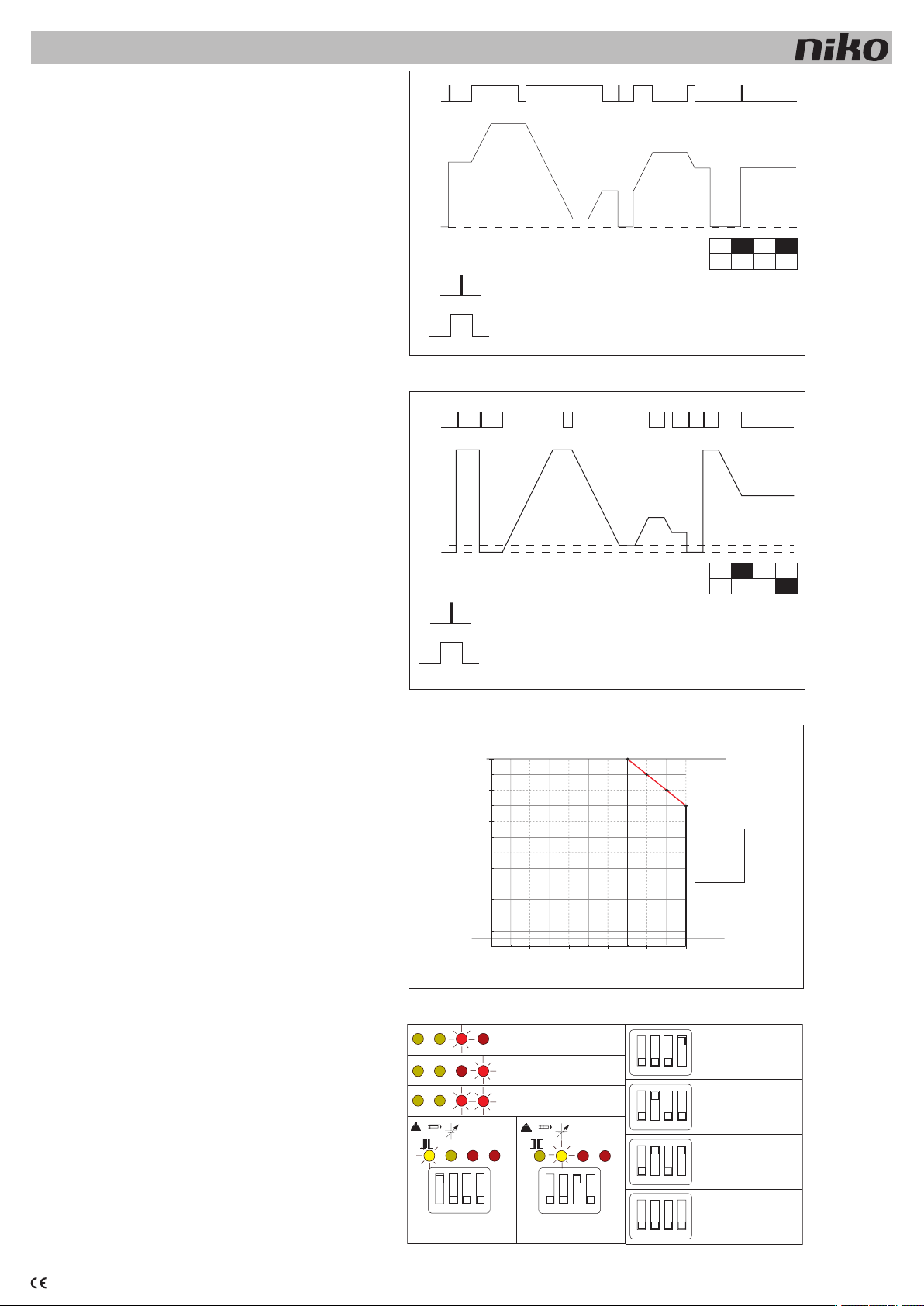
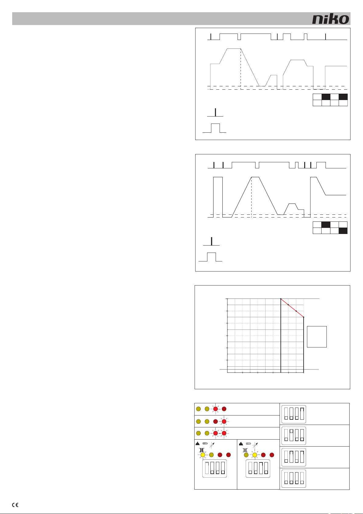
3.2 Drucktastenbedienung
Der Dimmer kann über jeden beliebigen potentialfreien Schließerkontakt
bedient werden. Kurz drücken für ein/aus, lange drücken, um die Helligkeit
des Lichts zu erhöhen/zu verringern (Abb. 1 & 2). Die Tasteransteuerung
ist im Dimmer galvanisch vom Netz getrennt. Die Verdrahtung kann für
Kleinspannung ausgeführt werden.
3.3 Warnhinweis
- Diese Geräte sind nicht für die Steuerung von Motoren geeignet, außer wenn
die spezifischen Schutzvorrichtungen durch externe Systeme gewährleistet
sind (automatischer Wiederanlauf nach Netzunterbrechung ist in diesem
Fall nicht zulässig).
- Dieses Gerät ist ausschließlich für die Montage auf Hutschiene geeignet
und muss in einen geschlossenen Verteiler eingebaut werden.
- Das Gerät darf erst dann unter Spannung gesetzt werden, nachdem die
nötigen Abdeckungen auf den Verteilerkasten montiert wurden.
4. EINSTELLUNGEN DER DIP-SCHALTER
Nummer ON OFF
1 PhasenANschnittsteuerung PhasenABschnittsteuerung
2 Drucktastenbedienung analoges Signal
3 0-10-V-Spannungssteuerung 1-10-V-Stromsenke
4 automatische Auswahl manuelle Auswahl
Gemischte Lasten dimmen und den Dimmer aktivieren
Eine gemischte Belastung besteht aus gewickelten Transformatoren (induk-
tiven Lasten) und elektronischen Transformatoren (kapazitiven Lasten), die
an demselben Dimmer angeschlossen sind. Lampen ohne Vorschaltgeräte
(z.B. Glühlampen) sind resistiv und bilden eine “neutrale” Belastung. Liegt
keine gemischte Belastung vor, siehe 4.1 und 4.2.
Vorsicht: Bei gemischter Belastung muss der Dimmer grundsätzlich auf
Phasenabschnitt eingestellt werden. Gemischte Lasten dürfen nicht im
Phasenanschnitt gedimmt werden. Wenn der Überspannungsschutz in
Phasenabschnitt eingeschaltet wird (rote LED Nr. 4 leuchtet auf), muss
die Induktivität kompensiert werden. Induktivitäten von gewickelten Trafos
werden genauso kompensiert wie Vorschaltgeräte von Leuchtstofflampen:
ein Kondensator der Klasse X-2 muss zwischen Phase und Nullleiter auf
der Primärseite des Trafos angeschlossen werden. Wert: ± 1µF pro 50VA.
Sollten Zweifel bezüglich des Belastungstyps bestehen, ist untenstehendes
Verfahren anzuwenden.
Stellen Sie den Dimmer auf Phasenabschnitt ein (dimming von elektronischen
Transformatoren und/oder ohmschen Lasten), indem Sie den Dip-Schalter
1 in die OFF-Position stellen (4.2). Wenn keine roten LEDs aufleuchten,
bedeutet dies, dass die Belastung überwiegend kapazitiv ist und dass die
Einstellung richtig ist.
Wenn eine oder mehrere rote LEDs aufleuchten und/oder der Dimmer nicht
funktioniert (Dimmer im Schutzmodus), bedeutet dies, dass die Belastung
überwiegend induktiv ist. In diesem Fall muss die Position des Dip-Schalters
1 auf ON (= Phasenanschnittsteuerung für induktive Lasten,4.1) geändert
werden. Drücken Sie die Reset-Drucktaste oder stellen Sie das analoge Signal
auf 0V, um den Dimmer neu zu starten. Resistive (ohmsche) Lasten sind neutral
und müssen in der Position für Phasenabschnitt geregelt werden.
4.1 Phasenanschnittsteuerung: Dip-Schalter 1 auf ON stellen
In diesem Modus können nur induktive Lasten (gewickelte Transformatoren)
geregelt werden. Alle sonstigen Lasten, einschließlich resistiver (ohmscher)
Lasten, müssen in der Phasenabschnitt geregelt werden (4.2). Wird dieser
Modus ausgewählt, leuchtet die gelbe LED 1 zur Kontrolle (5.1).
4.2 Phasenabschnittsteuerung: Dip-Schalter 1 auf OFF stellen
In diesem Modus können nur resistive (ohmsche) und kapazitive Lasten geregelt
werden. Diese dürfen gemischt werden. Es dürfen niemals nur induktive Lasten
in diesem Modus angeschlossen werden (4.1). Dieser Modus muss ebenfalls
für gemischte Lasten (induktiv + kapazitiv) ausgewählt werden.
Vorsicht: Elektronische Transformatoren mit mehr als 105VA sind für ein
Dimming nicht geeignet. Diese Transformatoren können unstabiles Licht
(Flimmern) bewirken. Wenn die Belastung nur kapazitiv ist, muss der Dimmer
min. belastet werden durch:
- 2 oder mehr elektronische Transformatoren;
- oder 1 elektronischen Transformator + 1 elektronische Vorlast (09-016-10).
Der Dimmer muss in diesem Modus eingeschaltet werden, wenn nicht
eindeutig ist, welcher Belastungstyp vorliegt.
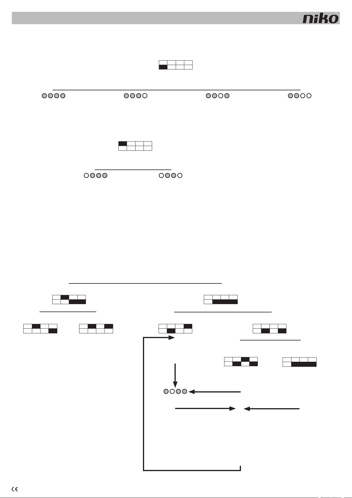
4.3 Drucktastenbedienung: Dip-Schalter 2 auf ON stellen
Diese Einstellung ermöglicht eine Betätigung über Öffnerkontakte. Durch
kurzes Drücken einschalten bzw. ausschalten. Durch längeres Drücken wird
die Helligkeit des Lichts erhöht/verringert. Bei längerem Drücken wird nach
jeder Unterbrechung die Richtung umgekehrt (Hell -> stop -> Dunkel -> stop
-> Hell -> ...). Das letzte Niveau wird in einem Speicher gespeichert (4.9).
4.4 Analoge Steuerungen: Dip-Schalter 2 auf OFF stellen
Anhand dieser Einstellung kann der Dimmer über analoge Steuersignale
gesteuert werden (4.8).
4.5 Automatische Auswahl des Typs Steuersignal (0-10 oder 1-10V):
Dip-Schalter 4 auf ON stellen.
In dieser Position muss der Dimmer den Typ Steuersignal automatisch
unterscheiden und selbst die Einstellung wählen (im Gegensatz zur manu-
ellen Einstellung unter 4.6). Diese Einstellung erfolgt nur beim Einschalten
der Stromversorgung. Bestimmungen bezüglich der Verwendung bei der
automatischen Auswahl:
Die manuelle Einstellung nur verwenden, wenn mehrere Dimmer mit demsel-
ben Steuerungsausgang verbunden sind. Durch Verwendung verschiedener
Dimmertypen kann die Detektion gestört werden. Wenn Dimmer 05-707 über
verschiedene Sicherungen verteilt sind, müssen alle Sicherungen innerhalb von
10s. eingeschaltet werden, um eine Störung der Detektion zu verhindern.
4.6 Manuelle Einstellung des Typs Steuersignal: Dip-Schalter 4
auf OFF stellen
In dieser Position wird der Steuersignaltyp (0-10 oder 1-10V) manuell durch
die Einstellung von Dip-Schalter 3 (4.7 und 4.8) festgelegt.
4.7 Manuelle Einstellung des Steuersignals auf 0-10V: Dip-Schalter
3 auf ON stellen
Um diese Funktion verwenden zu können, muss
- der Dip-Schalter 4 zuerst auf die Position OFF gestellt werden (manuelle
Einstellung des Steuersignals: siehe 4.6)
- der Dip-Schalter 2 auf OFF stehen (analoge Steuerung).
Bei Auswahl dieses Modus leuchtet die gelbe LED 2 zur Kontrolle auf. In
dieser Position muss der Dimmer ein Spannungssteuersignal von 0 bis 10V
gemäß der IEC 61131-2 Norm akzeptieren. Von 0 bis 10V ist eine Licht-
stärkeregelung von 0,1% bis max. Aussteuerung möglich. Unter 1V wird der
Dimmer ausgeschaltet (funktioniert als Halbleiterrelais)..
4.8 Manuelle Einstellung des Steuersignals auf 1-10V: Dip-Schalter
3 auf OFF stellen
Um diese Funktion verwenden zu können, muss
- der Dip-Schalter 4 zuerst auf Position OFF gestellt werden (manuelle
Einstellung des Steuersignals: siehe 4.6);
- der Dip-Schalter 2 auf OFF stehen (analoge Steuerung).
In dieser Position arbeitet der Dimmer über eine Stromsenke von 1 bis 10V
gemäß der EN60929 Norm (siehe auch 4.7). Von 0 bis 1V erfolgt keine
Lichtstärkeregelung. Von 1 bis 10V ist eine Lichtstärkeregelung von 0,1%
bis max. Aussteuerung möglich. Unter 1V wird der Dimmer ausgeschaltet
(funktioniert als Halbleiterrelais).
4.9 Drucktastenbedienung mit Speicher: Dip-Schalter 4 auf ON stellen Wenn
der Dimmer über die Drucktaste bedient wird (4.3), kann die Funktion mit
Speicher (Dip-Schalter 4 auf ON) oder die Funktion ohne Speicher (Dip-Schalter
4 auf OFF) gewählt werden. Ohne Speicher schaltet der Dimmer auf Max.
Mit Speicher schaltet der Dimmer auf den zuletzt eingestellten Wert. Nach
Einschaltung der Stromversorgung schaltet der Dimmer auf 20% ein.
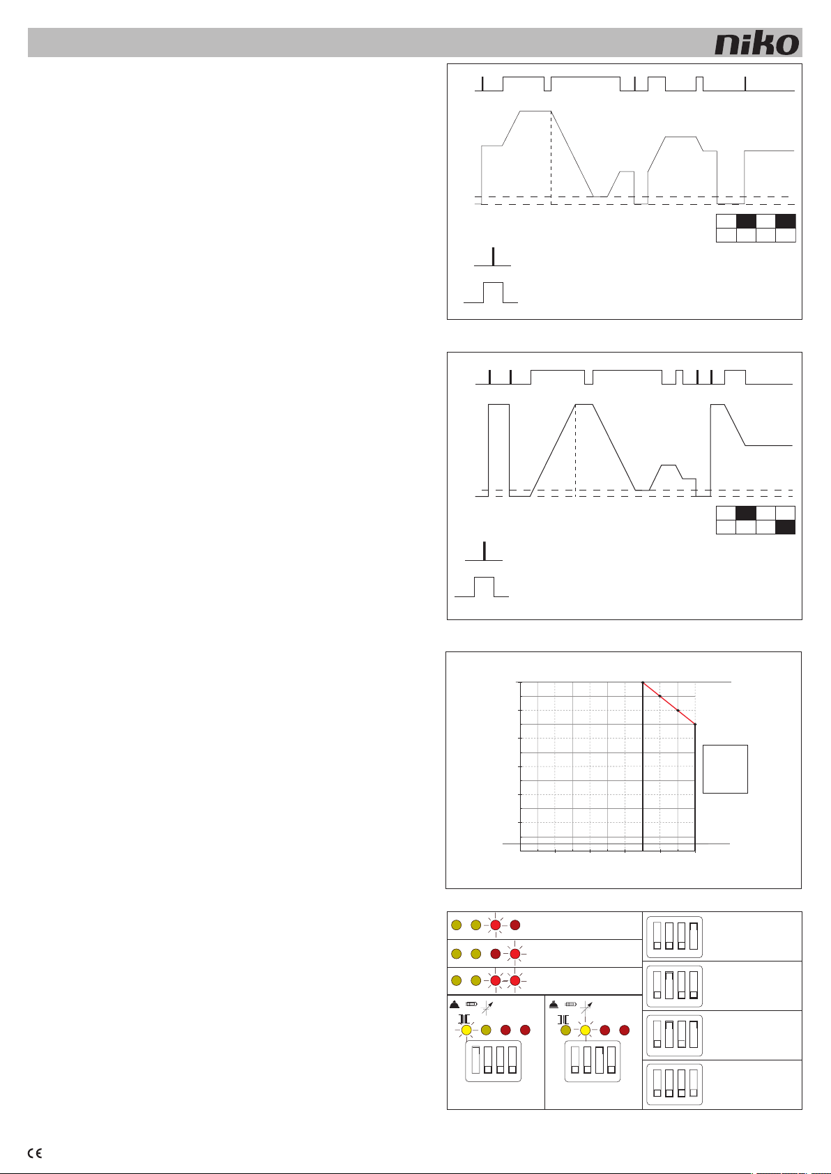
5. BETRIEBS- UND FEHLERKONTROLLE ÜBER LEDs
Dieser Dimmer ermöglicht eine Sichtkontrolle über 4 LEDs, die an der
Vorderseite der Dimmer nach der Installation sichtbar sein.
Von links nach rechts (Abb.4):
5.1 Anzeige der Funktionsweise in der Phasenanschnittsteuerung:
LED 1 leuchtet (gelb)
Symbol induktive Belastung über LED 1. Diese LED leuchtet, wenn der Dip-
Schalter 1 auf Position ON eingestellt wird.
5.2 Anzeige für die Auswahl des Steuersignals in Spannungssteu-
erung: LED 2 leuchtet (gelb)
Symbol geregelte Stromversorgung oben LED 2. Diese LED leuchtet auf,
wenn der Dip-Schalter 3 auf Position ON und die Dip-Schalter 4 und 2 auf
Position OFF eingestellt sind.
5.3.1 Überlast:
LED 3 leuchtet (rot)
Symbol I oben LED 3 und Angabe ‚overcurrent’ links von LED 3.
Dieser Schutz wird eingeschaltet, wenn
- der Dimmer überlastet ist;
- ein Kurzschluss im Belastungsstromkreis vorliegt.
Das Aufleuchten der roten LEDs weist auf die Aktivierung des Schutzes hin.
Dieser Schutz kann auftreten bei Einschaltspitzen oder Kurzschluss.
Wenn es zu einem Kurzschluss kommt, muss der Dimmer automatisch
ausgeschaltet werden.
Hinweis: Alle Sicherungssysteme werden beim Einschalten der Netzstromver-
sorgung aktiviert. Während eines einige Sekunden dauernden Vorgangs werden
diese nach und nach ausgeschaltet. Der Dimmer reagiert nicht auf das Signal der
Fernsteuerung, solange diese Kontrolle nicht erfolgreich abgeschlossen ist.
Nachdem der Fehler behoben wurde, kann der Dimmer auf folgende Weise
wieder eingeschaltet werden:
- Drücken der Reset-Drucktaste;
- Regelung des Steuersignals auf das Mindestniveau (0 bzw. 1V).
Vorsicht: Dieser Schutz ist kein Schutz für Personen. Es muss stets für
externen Schutz (automatische Sicherung) gesorgt werden.
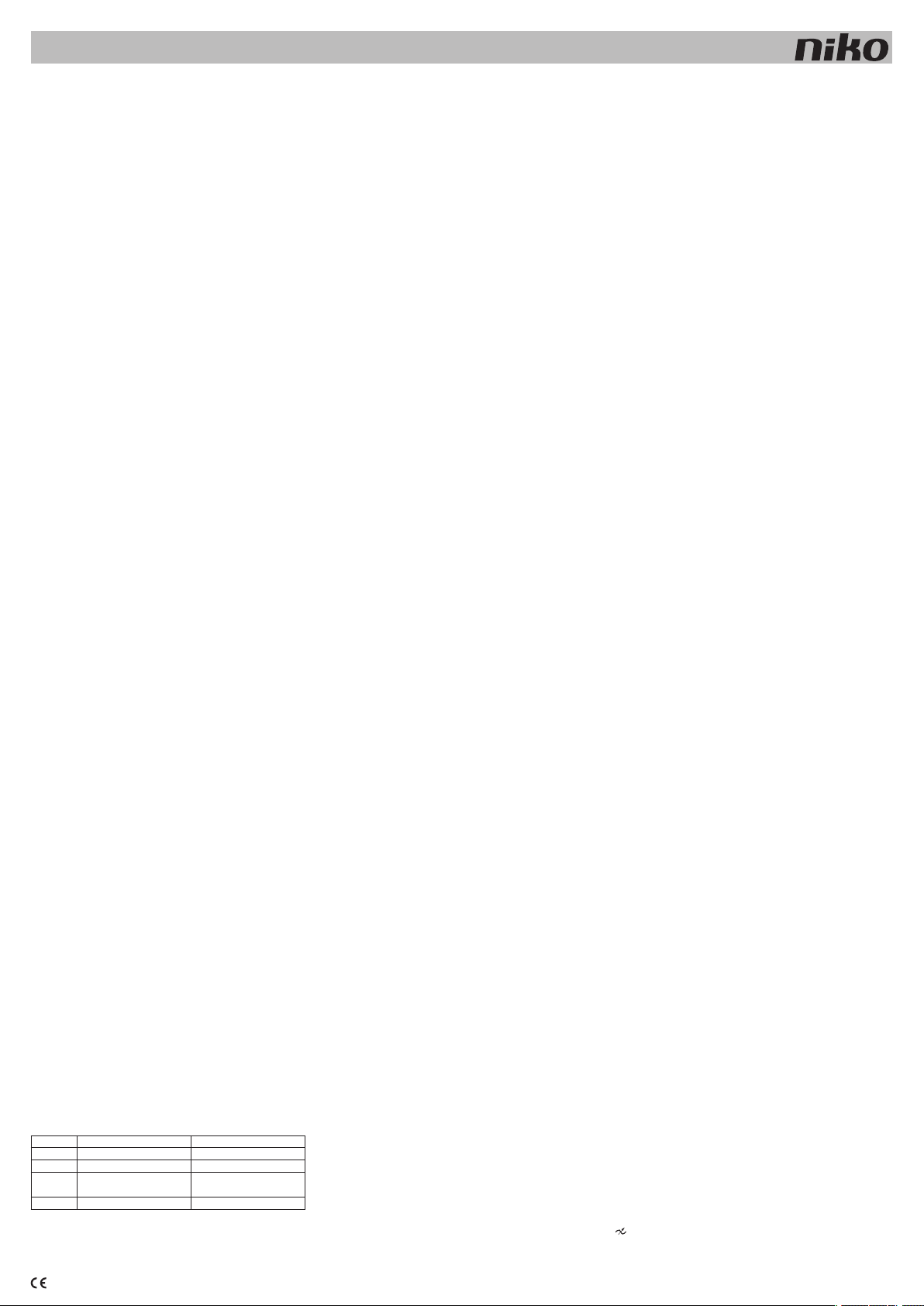
5.3.2 Erster thermischer Schutz:
LED 3 blinkt (rot)
Wenn die Temperatur der Kühlfläche mehr als 105°C beträgt, muss dieser
Schutz mit folgendem Ergebnis aktiviert werden:
- die dritte LED blinkt (rot);
- die Leistung des Dimmers wird bis 20% begrenzt (das Licht ist bis max.
20% regelbar).
Sobald die Temperatur vermindert wurde, erlischt die LED und ist der Dimmer
wieder normal regelbar.
5.4 Überspannungsschutz:
LED 4 leuchtet (rot)
Überspannungsschutz (Symbol U oben LED 4 und Angabe ‚overvoltage’
links von LED 4).
Dieser Schutz wird aktiviert, wenn eine Überspannung (höher als 480V
während mehr als 100µs) auftritt. Eine Überspannung kann mehrere Ursachen
haben, zum Beispiel:
- eventuelle vorübergehende Störungen beim 230V-Netz;
- magnetischer Transformator mit einer zu hohen Induktion, d.h. bei z.B.
unzureichender Belastung (Mindestbelastung bei magnetischen Transfor-
matoren: 75%);
- magnetischer Transformator mit Veränderung in der Belastung (defekte
Lampen nicht rechtzeitig ersetzt);
- der Dimmer ist nicht im richtigen Modus eingestellt, z.B. Dimmen von induktiven
Lasten in der Phasenabschnitt anstelle Phasenanschnittsteuerung (siehe 3).
Wenn der Schutzmodus aktiviert ist, weist dies auf eine anormale Situation
hin. Wenn der Dimmer in diesem Schutzmodus bleibt, muss der Fehler
gesucht und behoben werden.
Nachdem der Fehler behoben wurde, kann der Dimmer auf folgende Weise
wieder eingeschaltet werden:
- Drücken der Reset-Drucktaste;
- oder Regelung des Steuersignals auf das Mindestniveau (0 bzw. 1V).
5.5 Bezeichnung Gleichstromschutz oder thermischer Schutz:
LED 3 + 4 leuchtet
Bezeichnung Gleichstromschutz oder thermischer Schutz.
5.5.1 Gleichstromschutz
Wenn eine Asymmetrie von mehr als 1,5V gemessen wird, muss der Dim-
mer in den Schutzmodus wechseln. Dies ist insbesondere für das Dimmen
induktiver Lasten wichtig. Wenn der Dimmer versehentlich im Modus Pha-
senabschnitt induktive Lasten regelt, muss dieser Schutz aktiviert sein. Eine
zu hohe Asymmetrie verursacht Geräusche, Wärmeentwicklung und führt
zum Verschmoren von Transformatoren und Lampen.
5.5.2 Zweiter thermischer Schutzschalter
Der zweite thermische Schutzschalter hat eine selbsttätige Wiederherstellungs-
funktion. Bei Wärmeentwicklung wird das Gerät ab 115°C auf der Kühlfläche
ausgeschaltet. Solange der thermische Schutzschalter ausgeschaltet ist, muss
der Dimmer nicht auf das Steuersignal reagieren. Sobald der thermische
Schutzschalter wieder eingeschalten ist, schaltet der Dimmer zurück.
6. NETZANSCHLÜSSE
6.1 ganz oben von links nach rechts
L: 230V-Phase (Stromversorgung)
N: 230V-Nulleiter (Stromversorgung)
N: 230V-Nulleiter (Belastung) intern verbunden
: geregelte Phase (Belastung)
Der Nulleiter der Belastung muss mit dem Dimmer verbunden werden. Wenn
der Nulleiter direkt mit dem Netz verbunden wird, ist ein Funktionieren des
Dimmers nicht gewährleistet.
Vorsicht: Prüfen Sie vor dem Einschalten, ob alle Verbindungen ordnungs-
gemäß gespannt sind. Bei der Wartung der Installation muss den Druck auf
den Klemmen überprüft werden.
6.2 Steuerungsanschlüsse: analoges Signal
Steuerung mit analogem Signal (unten):
'-' Klemme: Masse des Steuersignals (0V)
'+' Klemme: Steuersignal: analoge Regelung von 0 oder 1 bis 10V

nv Niko sa Industriepark West 40, BE-9100 Sint-Niklaas, Belgium — tel. +32 3 760 14 70 — fax +32 3 777 71 20 — e-mail: [email protected] — www.niko.be PM005-70700R07154
05-707
Vorsicht: Dieselben Klemmen werden sowohl für die 0-bis-10-V-Spannungs- als auch
für die 1-bis-10-V-Stromsenke und Drucktastenbedienung verwendet. Die Polarität muss
eingehalten werden. Bei Verbindung mehrerer Dimmer an ein und demselben Steuerungs-
ausgang darf '-' und '+' niemals verwechselt werden.
Der Steuerungseingang ist galvanisch getrennt. Die Isolierung innerhalb der Dimmer gewährt
eine Steuerung mit Kleinspannung.
Die 1-10-V-Stromsenke ist in der europäischen Norm EN60929 beschrieben. Diese Steu-
erungstechnik wird hauptsächlich für die Steuerung von elektronischen Vorschaltgeräten
(EVSA) mittels sogenannter elektronischer Potentiometer wie z.B. 09-011 verwendet. Durch
die durch den Steuerstromkreis fließende Stromstärke wird das Lichtniveau bestimmt. Diese
sogenannten stromsenke unterscheiden sich grundlegend von den 0-10-V-Steuersignalen,
die als 'source'-Signale bezeichnet werden. Die 0-10-V-Spannungs- oder 'source'-Signale
kommen typischerweise in professionellen Anwendungen wie PLC’s (SPS), Silicon Controls
Steuersystemen oder beim Nikobus dimcontroller 05-007-02 zum Einsatz.
6.3 Steuerungsanschlüsse: Drucktastenbedienung
Steuerung mit N.O.-Kontakten (unten):
'-' Klemme: gemeinsam aller Kontakte
'+' Klemme: Signal
Die Drucktasten dürfen in keinem Fall mit dem Netz verbunden werden.
7. TEST
Der Dimmer kann permanent mit max. Aussteuerung schalten, wenn folgende einfache
Vorkehrungen getroffen werden:
- die 230-V-Stromversorgung zweipolig unterbrechen;
- den Dip-Schalter Nr. 4 in Position OFF (manuelle Auswahl) stellen;
- den Dip-Schalter Nr. 2 in Position OFF (analoge Steuerung) stellen;
- den Dip-Schalter Nr. 3 in Position OFF (1-10 V) stellen;
- die beiden 10-V-Steuerungsdrähte lösen;
- die 230-V-Stromversorgung einschalten;
Die Leuchte leuchtet mit max. Helligkeit, ohne dass ein Steuersignal erforderlich ist.
Warnhinweis: Die Dimmer werden niemals durch eine Betätigung der Steuerung elektrisch
vom Netz getrennt. Alle Teile, einschließlich der Lampen, bleiben somit unter Spannung, auch
wenn das Licht ausgeschaltet ist.
Signale, die über das Netz gesteuert werden, können den Funktionsablauf der Dimmer stören.
Die Störung tritt nur auf, wenn das betreffende Signal über das Netz gesteuert wird.
8. KÜHLUNG
Die Kühlung ist für eine betriebssichere Verwendung wesentlich.
Der Dimmer produziert ungefähr 1,2% Wärme bezüglich des angeschlossenen Ver-
brauchs.
z.B.: 500W Beleuchtung = 6W Wärmeverlust
Sorgen sie dafür, dass ausreichend kühle Luft zugeführt wird. Wenn die natürliche Luftzirku-
lation eingeschränkt ist, muss ein Ventilator im Gehäuse oder vor Ort vorgesehen werden.
Nominale Umgebungstemperatur: 20°C
9. ENTSTÖRUNG
Störung über die Stromversorgungskabel: Der Entstörungsgrad entspricht der Europäischen
Norm (EN55015) sowie den internationalen Normen (CISPR15).
10. TECHNISCHE DATEN
Stromversorgung: 230V~ 50Hz
Abmessungen: (H x B x T) 89 x 70 x 54,5mm
Gewicht: 0,216kg
Mindestbelastung: 35W oder 2 elektronische Transformatoren
Höchstbelastung: siehe Leistungstabelle (Abb. 3)
Wichtig: Die Höchstbelastung ist hauptsächlich von der Umgebungstemperatur abhängig
(Abb. 3).
Besonderer Hinweis in Verbindung mit induktiven Lasten:
- gewickelte Transformatoren müssen mindestens zu 75 % belastet sein;
- die Leistung von gewickelten Transformatoren muss um den Faktor cosinus phi erhöht
werden;
- bei Verwendung von Ringkerntransformatoren ist die Höchstbelastung auf 450W be-
grenzt.
11. WARTUNG
Diese Geräte sind für eine Verwendung unter folgenden Bedingungen ausgelegt:
- eine Umgebungstemperatur von 35°C;
- einen nicht-kondensierenden Luftfeuchtigkeitsgrad;
- eine Netzspannung von 230V.
Zumindest die im folgenden aufgeführten Punkte müssen nach vollständiger Ausschaltung
der Netzstromversorgung regelmäßig überprüft werden:
- Druck der Anschlussklemmen;
- Lüftung.
12. GARANTIEBESTIMMUNGEN
- Garantiezeitraum: Zwei Jahre ab Lieferdatum. Als Lieferdatum gilt das Rechnungsdatum
zu dem der Endkunde das Produkt gekauft hat. Falls keine Rechnung mehr vorhanden
ist, gilt das Produktionsdatum.
- Der Endkunde ist verpflichtet, Niko über den festgestellten Mangel innerhalb von zwei
Monaten zu informieren.
- Im Falle eines Mangels an dem Produkt hat der Endkunde das Recht auf eine kostenlose
Reparatur oder Ersatz. Dies wird von Niko entschieden.
- Niko ist nicht für einen Mangel oder Schaden verantwortlich, der durch unsachgemäße
Installation, nicht bestimmungsgemäßen oder unvorsichtigen Gebrauch oder falsche
Bedienung oder Anpassen/Ändern des Produktes entsteht.
- Die zwingenden Vorschriften der nationalen Gesetzgebung bezüglich des Verkaufs von
Konsumgütern und der Schutz des Kunden in den Ländern in denen Niko direkt oder über
seine Tochtergesellschaften, Filialen, Distributoren, Handelsvertretungen oder Vertretern
verkauft, haben Vorrang vor den obigen Bestimmungen.
Drukknopbediening 05-707
Met geheugen: DIP-switch 2 op ON
DIP-switch 4 op ON
kort drukken (<0,4s.) = ON / OFF
lang drukken (>0,4s.) = UP / DOWN
Bij stijgen: stop op 100%
Bij dalen, stop 2s. op min., daarna stijgen.
Herhaaldelijk drukken keert de dimrichting om.
ON /OFF
UP / DOWN
0%
min.
100%
I
0
2s.
4s.
Drukknopbediening 05-707
Zonder geheugen: DIP-switch 2 op ON
DIP-switch 4 op OFF
kort drukken (<0,4s.) = ON / OFF
lang drukken (>0,4s.) = UP / DOWN
Bij stijgen: stop op 100%
Bij dalen, stop 2s. op min., daarna stijgen.
Herhaaldelijk drukken keert de dimrichting om.
0%
min.
100%
I
0
2s.
4s.
ON /OFF
UP / DOWN
600
500
400
300
200
100
10 20 30 40 50
MIN.
Belasting
MAX.
Belasting
°C
W
a
t
Omgevingstemperatuur
memo
35°C = 600W
40°C = 550W
45°C = 500W
50°C = 450W
ON
OFF
I U
0 - 10V
1234
HAL.12 - 24V
ON
OFF
I U
0 - 10V
1234
HAL.12 - 24V
Phasenanschnitt (induktiv)
1 OFF = Phasenabschnitt (res.+kap)
Überlastschutz
(Kurzschluss oder Überlast)
Überspannungschutz
(Phasenabschnitt anstatt Phasenanschnitt,
defekte Belastung, Netzstörung)
Gleichstrom oder thermischer Schutz
Manuelle Einstellung des
Signals auf 0-10V
3 OFF = analog 1-10V
ON
OFF
1234
1 Phasenabschnitt
2 Analoge Ansteuerung
3 Einstellung auf1-10V
4 Manuelle Auswahl des Steuer-
signals auf (0-10V oder 1-10V)
ON
OFF
1234
Drucktastenbedienung
2 OFF = analoge Ansteuerung
ON
OFF
1234
Drucktastenbedienung
mit Speicher
4 OFF = ohne Speicher
ON
OFF
1234
Automatische Auswahl des
Signals (0-10V oder 1-10V)
4 OFF = manuelle Auswahl
Abb.1
Abb.2
Abb.3
Abb.4
Druckknopfbedienung 05-707
mit Speicher: Dip-Schalter 2 AUF ‘ON’
Dip-Schalter 4 AUF ‘ON’
kurz drücken (<0,4s.)= EIN/AUS
lange drücken (>0,4s.)= HELL/DUNKEL
Beim Erhöhen: Stopp bei 100 %
Beim Verringern: Stopp von 2s. beim Minimum, danach Erhöhen
Durch wiederholtes Drücken wird die Richtung der Beleucht-
ungsregelung umgekehrt.
Druckknopfbedienung 05-707
ohne Speicher: Dip-Schalter 2 AUF ‘ON’
Dip-Schalter 4 AUF ‘OFF’
kurz drücken (<0,4s.)= EIN/AUS
lange drücken (>0,4s.)= HELL/DUNKEL
Beim Erhöhen: Stopp bei 100 %
Beim Verringern: Stopp von 2s. beim Minimum, danach Erhöhen
Durch wiederholtes Drücken wird die Richtung der Beleucht-
ungsregelung umgekehrt.
Umgebungstemperatur
Min.
Belastung
Max.
Belastung

nv Niko sa Industriepark West 40, BE-9100 Sint-Niklaas, Belgium — tel. +32 3 760 14 70 — fax +32 3 777 71 20 — e-mail: [email protected] — www.niko.be PM005-70700R07154
05-707
Schritt 1 (einstellen Schaltprinzip) Netzversorgung ausschalten
➡
Netz und Last Verbinden
(Steuerung nicht Verbinden)
➡
Phasenabschnitt einstellen
➡
Netzversorgung einschalten
➡
➡
➡
➡
➡
OK
➡
➡
➡
Resitive Lasten Überspannungschutz Überlast oder Kurzschluss Dimmer nicht belastet
Kapazitive Lasten
➡
➡
➡
(elektronische Transformatoren) Netzversorgung Netzversorgung Netzversorgung
Gemischte Lasten ausschalten ausschalten ausschalten
➡
➡
➡
➡
Weiter mit Schritt 2 PhasenANschnitt einstellen Kurzschluss korrigieren Last verbinden
oder Last verminderen
➡
➡
Netzversorgung einschalten
➡
Netzversorgung einschalten
➡
➡
➡
OK
➡
Induktive lasten Überlast
(gewickelte
➡
Transformatoren) Netzversorgung
➡
ausschalten
Weiter mit Schritt 2 Last vermindern
➡
Netzversorgung einschalten
Schritt 2 (Einstellen Steuerung) Netzversorgung ausschalten
➡
Steuerung verbinden
➡
Steuerung Auswahl
➡
➡
➡
Drucktasterbedienung (Siehe 4.3) Analoge Steuerung (Siehe 3.1)
➡
➡
➡
➡
➡
➡
ohne Speicher (Siehe 4.9) mit Speicher (Siehe 4.9) Automatische Auswahl (Siehe 4.5) Manuelle Auswahl (Siehe 4.6)
➡
➡
➡
➡
Netzversorgung einschalten Netzversorgung einschalten Netzversorgung einschalten
➡
➡
➡
➡
➡
0-10V analoge Steuerung 1-10V analoge Steuerung
Drucktaste kurz eindrücken Drucktaste Kurz eindrücken 10s. warten (Siehe 4.7) (Siehe 4.8)
➡
➡
➡
Dimmer auf max. Helligkeit Dimmer ein auf 20%
➡
➡
➡
➡
Kurz eindrücken für ausschalten Lang eindrücken für ⇑⇓ Netzversorgung Netzversorgung
➡
➡
einschalten einschalten
OK OK
➡
➡
elektronisches
➡
Potentiometer
Steuersignal ändern bedienen
➡
➡
➡
Dimmer folgt Dimmer folgt nicht Dimmer folgt
➡
➡
➡
OK Netzversorgung OK
ausschalten
➡
“+” und “-” umdrehen
➡
Weiter verfahren
➡

nv Niko sa Industriepark West 40, BE-9100 Sint-Niklaas, Belgium — tel. +32 3 760 14 70 — fax +32 3 777 71 20 — e-mail: [email protected] — www.niko.be PM005-70700R07154
05-707
Congratulations on your purchase of this product from the Niko dimmer
range.
1. LEGAL WARNINGS
- Read the complete manual before attempting installation and activating
the system.
- The installation has to be carried out by a qualified person and in compli-
ance with the statutory regulations.
- This user manual has to be handed over to the user. It has to be included
in the electrical installation file and has to be passed on to any new
owners. Additional copies are available on the Niko website or via the
support service.
- During installation, the following has to be taken into account (not limited
to list below):
- The statutory laws, standards and regulations;
- The state of the art technique at the moment of installation;
- This user manual, which must be read within the scope of each specific
installation, only states general regulations;
- The rules of proper workmanship
- In case of questions, you can consult Niko’s support service or contact
a registered control organisation.
Support Belgium: Support Slovakia:
+32 3 760 14 82 +421 263 825 155
e-mail: [email protected]
In case of a defect, you can return your product to a registered Niko
wholesaler, together with a clear description of your complaint (Conditions
of use, stated defect…).
2. DESCRIPTION
Controlling the intensity (dimming) of all dimmable loads except for fluo-
rescent lamps.
Resistive loads: incandescent lamps, 230V halogen lamps...
Inductive loads: ferromagnetic transformers
Capacitive loads: electronic transformers...
3. OPERATION AND USE
This dimmer (05-707) operates with power transistors instead of triacs. This
allows both phase control and reverse phase control dimming.
In phase control, the dimmer is switched off at the zero crossing and
switched on beforehand. This switch technique is recommended for
inductive loads (ferromagnetic transformers). In reverse phase control, the
dimmer is switched on at the zero crossing and switched off afterwards.
This switch technique is recommended for:
- capacitive loads (dimmable, electronic transformers 230V~);
- resistive loads;
- mixed loads (above-mentioned + inductive loads) connected to the
same dimmer.
Because the interference suppression is full-electronic and no chokes are
used, these dimmers are completely silent and up to 30% lighter than
classic dimmers. The technology used enables to electronically protect the
dimmer against short-circuit, overcurrent and overvoltage.
This dimmer is remote controlled either via an analog signal or via potentialfree
N.O. contacts (e.g. 07-000). The control is galvanically separated from the
mains. Both the analog and the push button wiring is carried out under very
low voltage. A lamp that is connected via dimmers cannot be dimmed to
the max. light intensity. The light intensity will always be less in comparison
with an identical lamp that is directly connected to the mains.
3.1 Analog control (e.g. via Nikobus 05-007-02)
This dimmer (05-707) can be remote controlled with any device that complies
to the international 0-10V (voltage control) and the 1-10V (current control)
standard. Operation is analogue (0V = off, 10V = max. light intensity). Analog
control and signal cables are galvanically separated from the mains via the
dimmer. The wiring is carried out in ELV (extra low voltage).
3.2 Push button control
Any potentialfree N.O. contact can control the dimmer. Press briefly for
on/off, press long to increase/decrease (fig. 1 & 2). The push buttons are
galvanically separated from the mains via the dimmer. The wiring is carried
out in ELV (extra low voltage).
3.3 Warning
- This devices are not suitable for controlling motors, unless the specific
safety requirements are guaranteed by external systems (in this case,
automatic restart after power cut is not allowed).
- This device is exclusively suitable for DIN-rail mounting and must be
mounted in a closed distribution board.
- This device can only be connected to the power supply after installation
of the necessary covers in the distribution board.
4. DIP SWITCH SETTINGS
Number ON OFF
1 phase control reverse phase control
2 push button operation analog signal
3 0-10V voltage control 1-10V current control
4 automatic selection manual selection
Dimming mixed loads and activating the dimmer
A mixed load consists of wound transformers (inductive loads) and electronic
transformers (capacitive loads) that are connected to the same dimmer.
Lamps without control gear (e.g. incandescent lamps) are resistive and
form a neutral load. If the load is not mixed, see 4.1 and 4.2.
Attention: for dimming mixed loads, the dimmer has to be set in reverse
phase control. Mixed loads cannot be dimmed in phase control. Induction
must be compensated in case the overvoltage protection is activated in
reverse phase control (red LED no. 4 lights). Inductions of wound transformers
are compensated in the same way as ballasts of fluorescent lamps: place
a X-2 class capacitor between phase and neutral on the primary side of
the transformer. Value ± 1micro Farad per 50VA.
Follow the procedure described below if you are in doubt as to the type
of load.
Set the dimmer in reverse phase control (dimming electronic transformers
and/or resistive loads) by switching DIP switch 1 to OFF (4.2). If no red
LEDs light, this means that the load is predominantly capacitive and that
the setting is correct.
If one or more red LEDs light and/or the dimmer does not work (dimmer
in protective mode), this means that the load is predominantly inductive.
In this case, switch the DIP switch 1 to ON (= phase control for inductive
loads, see 4.1). Press the reset key or set the analog signal to 0V to restart
the dimmer. Resistive loads are neutral and have to be dimmed in reverse
phase control.
4.1 Phase control: switch DIP switch 1 to ON
Only inductive loads (ferromagnetic transformers) can be dimmed in this
mode. All other loads, incl. resistive loads, have to be dimmed in reverse
phase control (4.2). When this mode is selected, yellow LED 1 lights as a
check (5.1).
4.2 Reverse phase control: switch DIP switch 1 to OFF
Only resistive and capacitive loads can be dimmed in this mode. These
loads can be mixed. Never connect only inductive loads in this mode (4.1).
Also use this mode for mixed loads (inductive + capacitive).
Attention: electronic transformers of over 105VA are not suitable for dim-
ming. These transformers can produce unstable light (blinking). If the load
is purely capacitive, the dimmer must be at least loaded by:
- 2 or more electronic transformers;
- or 1 electronic transformer + 1 electronic auxiliary load (09-016-10).
Switch the dimmer to this mode if you are in doubt as to the type of
load.
4.3 Push button control: switch DIP switch 2 to ON
This setting enables control via N.O. contacts. Press briefly for on/off. Press
long to increase/decrease. When pressing long, the dim direction is reversed
after each interruption (increase -> stop -> decrease -> stop -> increase
-> …). The last level can be stored in a memory (4.9).
4.4 Analog controls: switch DIP switch 2 to OFF
This setting enables to control the dimmer via analog control signals (4.8).
4.5 Automatic selection of the type of control signal (0-10 or 1-
10V): switch DIP switch 4 to ON
In this mode, the dimmer will automatically discern the type of control
signal and choose the setting (as opposed to the manual setting described
in 4.6). This setting is only made when the power supply is switched on.
Conditions for the use of automatic selection:
Only use the manual setting if several dimmers are connected to the same
control output. The use of different types of dimmers can affect the detec-
tion. If 05-707 dimmers are distributed over different fuses, all fuses must
be switched on within 10s. to avoid detection problems.
4.6 Manually setting the control signal: switch DIP switch 4 to
OFF
In this mode, the type of control signal (0-10 or 1-10V) is manually selected
by the setting of DIP switch 3 (4.7 and 4.8).
4.7 Manually setting the control signal to 0-10V: switch DIP switch
3 to ON
To use this function:
- DIP switch 4 first has to be switched to OFF (manually setting the control
signal: see 4.6)
- DIP switch 2 has to be switched to OFF (analog control).
When this mode is selected, yellow LED 2 lights as a check. In this posi-
tion, the dimmer will accept a voltage control signal from 0 to 10V in
accordance with the IEC standard 61131-2. From 0 to 10V it is possible
to adjust the light intensity from 0.1% to max. The dimmer is switched off
at 1V (functions as a solid-state relay).
4.8 Manually setting the control signal to 1-10V: switch DIP switch
3 to OFF
To use this function:
- DIP switch 4 first has to be switched to OFF (manually setting the control
signal: see 4.6).
- DIP switch 2 has to be switched to OFF (analog control).
In this position, the dimmer operates via a current control signal from 1 to
10V in accordance with the EN60929 standard (see also 4.7). From 0 to
1V, there is no adjustment of the light intensity. From 1 to 10V it is possible
to adjust the light intensity from 0.1% to max. The dimmer is switched off
at 1V (functions as a solid-state relay).
4.9 Push button operation with memory: switch DIP switch 4 to ON
If the dimmer is controlled via a push button (4.3), you can choose operation
with memory (DIP switch 4 to ON) or without memory (DIP switch 4 to OFF).
Without memory, the dimmer switches on at max. light intensity. With memory,
the dimmer switches on at the last set value. After the power voltage has been
switched on, the dimmer switches on at 20%.
5. OPERATIONAL AND ERROR CONTROL BY MEANS OF LEDS
This dimmer is provided with a visual control function by means of 4 LEDs
which remain visible on the front of the dimmer after installation.
From left to right (fig.4):
5.1 Indication of operation in phase control:
LED 1 lights (yellow)
Inductive load symbol above LED 1. This LED lights when DIP switch 1
is switched to ON.
5.2 Indication of control signal selection in voltage control:
LED 2 lights (yellow)
Regulated supply symbol above LED 2. This LED lights when DIP switch 3
is switched to ON and DIP switches 4 and 2 are switched to OFF.
5.3.1 Overcurrent:
LED 3 lights (red)
Symbol I above LED 3 and ‘overcurrent’ indication to the left of LED 3.
This protection is activated if:
- the dimmer is overloaded;
- there is a short-circuit in the load circuit.
If the red LED lights, the protection is activated. This can happen in case
of switch-on surges or short-circuits.
In case of a short-circuit, the dimmer is automatically switched off.
Note: all protection systems are active when the mains supply is switched
on. For several seconds, they are deactivated one after the other. The dim-
mer does not react to the remote control signal for as long as this control
has not been completed successfully.
Once the error has been rectified, the dimmer can be switched back
on as follows:
- press the reset key;
- adjust the control signal to min. level (0 or 1V resp.).
Attention: this protection is not intended for people. An external automatic
protection (automatic fuse) must always be provided.
5.3.2 First thermal protection:
LED 3 blinks (red)
If the temperature of the cooling surface exceeds 105°C, this protection
is activated and:
- the third LED blinks (red);
- the power of the dimmer is restricted to 20% (the light intensity can be
adjusted to max. 20%).
As soon as the temperature has dropped, the LED goes out and the dimmer
can be operated normally again.
5.4 Overvoltage protection:
LED 4 lights (red)
Overvoltage protection (symbol U above LED 4 and ‘overvoltage’ indication
to the left of LED 4).
This protection is activated if an overvoltage (greater than 480V for more
than 100µs.) occurs. An overvoltage can have several causes:
- a temporary or otherwise fault on the 230V mains;
- magnetic transformer with a too high induction caused by e.g. insufficient
load (min. load of magnetic transformers 75%);
- magnetic transformer with change in the load (defective lamps not
replaced in time);
- the dimmer is not set to the correct mode, e.g. dimming inductive loads
in reverse phase control instead of phase control (see 3).
If the protection is activated, this indicates an abnormal situation. If the
dimmer stays in protection mode, the error must be found and rectified.
Once the error has been rectified, the dimmer can be switched back
on as follows:
- press the reset key;
- or adjust the control signal to min. level (0 or 1V resp.).
5.5 Indication of direct current or thermal protection:
LEDs 3 + 4 light
Indication of direct current or thermal protection.
5.5.1 Direct-current protection
If an asymmetry of over 1.5V is measured, the dimmer will enter protec-
tion mode. This is particularly important for dimming inductive loads. If
the dimmer mistakenly dims inductive loads in reverse phase control, this
protection will be activated. An too high asymmetry causes humming,
heating and ultimately burning of transformers and lamps.
5.5.2 Second thermal protection
The second thermal protection is self-restoring. In case of overheating, the
device is switched off from 115°C on the cooling surface. For as long as
the thermal protection is activated, the dimmer will not react to the control
signal. If the temperature has dropped, the dimmer switches back on.
6. MAINS CONNECTIONS
6.1 top from left to right
L: 230V phase (power supply)
N: 230V neuter (power supply)
N: 230V neuter (load) interconnected
: regulated phase (load)
The neuter of the load must be connected to the dimmer. If the neuter
is directly connected to the mains, the operation of the dimmer is not
guaranteed.
Attention: before switching on, check whether all connections are secure.
During maintenance on the installation, the pressure on the terminals
must be checked.
6.2 control connections: analog signal
Control with analog signal (bottom):
'-' terminal: mass of the control signal (0V)
'+' terminal: control signal: analog control from 0 or 1 to 10V
Attention: the same terminals are used both for 0-10V voltage control
and 1-10V current control and push button control. Take into account
the polarity. In case several dimmers are connected to one and the same
control output, never confuse the '-' and '+'.
The control input is galvanically separated. The insulation within the dimmer
guarantees control at extra low voltage.
The 1-10V current control is described in the European standard EN60929.
This control technique is mainly used for controlling electronic control gear
(ECG) by means of so-called electronic potentiometers e.g. 09-011. The
intensity of the current passing through the control circuit determines the
light intensity. These so-called “current sink” control signals fundamentally
differ from the 0-10V control signals, known as “source” signals. The
0-10V voltage or “source” signals are typically used in professional ap-
plications such as: PLCs, Silicon Controls control systems or the Nikobus
dim controller 05-007-02.
6.3 Control connections: push button control
Control with N.O. contacts (bottom):
'-' terminal: common for all contacts
'+' terminal: signal
The push buttons can under no circumstances be connected to the mains.

nv Niko sa Industriepark West 40, BE-9100 Sint-Niklaas, Belgium — tel. +32 3 760 14 70 — fax +32 3 777 71 20 — e-mail: [email protected] — www.niko.be PM005-70700R07154
05-707
Drukknopbediening 05-707
Met geheugen: DIP-switch 2 op ON
DIP-switch 4 op ON
kort drukken (<0,4s.) = ON / OFF
lang drukken (>0,4s.) = UP / DOWN
Bij stijgen: stop op 100%
Bij dalen, stop 2s. op min., daarna stijgen.
Herhaaldelijk drukken keert de dimrichting om.
ON /OFF
UP / DOWN
0%
min.
100%
I
0
2s.
4s.
Drukknopbediening 05-707
Zonder geheugen: DIP-switch 2 op ON
DIP-switch 4 op OFF
kort drukken (<0,4s.) = ON / OFF
lang drukken (>0,4s.) = UP / DOWN
Bij stijgen: stop op 100%
Bij dalen, stop 2s. op min., daarna stijgen.
Herhaaldelijk drukken keert de dimrichting om.
0%
min.
100%
I
0
2s.
4s.
ON /OFF
UP / DOWN
600
500
400
300
200
100
10 20 30 40 50
MIN.
Belasting
MAX.
Belasting
°C
W
a
t
Omgevingstemperatuur
memo
35°C = 600W
40°C = 550W
45°C = 500W
50°C = 450W
ON
OFF
I U
0 - 10V
1234
HAL.12 - 24V
ON
OFF
I U
0 - 10V
1234
HAL.12 - 24V
Phase control (inductive loads)
1 OFF = Reverse phase control
(res. + cap.)
Overcurrent protection
(Short-circuit or overload)
Overvoltage protection (Reverse phase
control instead of phase control or
defective load or surges on the mains)
DC or thermal protection
Manually setting the
control signal to 0-10V
3 OFF = Analog 1-10V
ON
OFF
1234
1 Reverse phase control
2 Analog control
3 Manually setting the
control signal to 1-10V
4 Manual signal selection
(0-10V or 1-10V)
ON
OFF
1234
Push button control
2 OFF = Analog control
ON
OFF
1234
Push button control
with memory
4 OFF = Without memory
ON
OFF
1234
Automatic selection of
control signal (0-10V or 1-10V)
4 OFF = Manual selection
7. TEST
The dimmer can permanently operate at max. with a simple setting:
- bipolarly disconnect the 230V power supply;
- switch DIP switch 4 to OFF (manual selection);
- switch DIP switch 2 to OFF (analog control);
- switch DIP switch 3 to OFF (1-10V);
- disconnect both 10V control wires;
- connect the 230V power supply;
The dimmer now switches to max. without requiring a control signal
Warning: the dimmers are never electrically separated from the mains
by operating the control. All components, incl. the lamps, therefore remain
live even when the light is “off”.
Signals that are sent via the mains, can interfere with the operation of the
dimmer. This interference only occurs if this signal is sent via the mains.
8. COOLING
Cooling is essential for reliable and safe operation.
The dimmer produces approx. 1.2% heat vs the connected load.
E.g.: 500W lighting = 6W dissipation
Provide sufficient cool air circulation with regard to the total dissipated
power. If the natural air circulation is limited, a fan must be provided in
the cabinet or in the room.
Nominal ambient temperature: 20°C
9. INTERFERENCE SUPPRESSION
Interference over the power supply cables: the degree of interference sup-
pression complies to the European (EN55015) and international (CISPR15)
standards.
10. TECHNICAL DATA
power supply: 230V~ 50Hz
dimensions: (H x W x D) 89 x 70 x 54.5mm
weight: 0.216kg
min. load: 35W or 2 electronic transformers
max. load: see load table (fig. 3)
Important: the max. load mainly depends on the ambient temperature
(fig. 3).
Special remarks with regard to inductive loads:
- ferromagnetic (wound) transformers have to be loaded for min. 75%;
- the consumption of ferromagnetic transformers must be increased by
the cosine phi;
- in case toroidal core transformers are used, the max. load is limited to
450W.
11. MAINTENANCE
These appliances are suitable for use in the following conditions:
- an ambient temperature of 35°C;
- a environment with a non-condensing atmospheric humidity;
- a mains voltage of 230V.
A regular check of at least the following is recommended after the power
supply has been switched off completely:
- pressure of the screw terminals;
- ventilation.
12.GUARANTEE PROVISIONS
- Period of guarantee: 2 years from date of delivery. The delivery date is
the invoice date of purchase of the product by the consumer. If there is
no invoice, the date of production applies.
- The consumer is obliged to inform Niko in writing about the defect,
within two months after stating the defect.
- In case of a failure to conform, the consumer has the right to a repair
or replacement (decided by Niko) free of charge.
- Niko cannot be held liable for a defect or damage as a result of an incorrect
installation, improper or careless use or wrong usage or transformation
of the goods.
- The compulsory regulations of the national legislation concerning the
sales of consumer goods and the protection of the consumers in the
countries where Niko sells, directly or via sister or daughter companies,
chain stores, distributors, agents or permanent sales representatives,
take priority over the rules and regulations mentioned above.
fig.1
fig.2
fig.3
fig.4
Push button control 05-707
With memory: DIP Switch 2 to ON
DIP Switch 4 to ON
Press briefly (<0,4s.) = ON / OFF
Press long (>0,4s.) = UP / DOWN
Dimming UP: stop at 100%
Dimming DOWN: stop for 2s. at min. level then dim UP
Press repeatedly: reverse dim direction.
Push button control 05-707
Without memory: DIP Switch 2 to ON
DIP Switch 4 to OFF
Press briefly (<0,4s.) = ON / OFF
Press long (>0,4s.) = UP / DOWN
Dimming UP: stop at 100%
Dimming DOWN: stop for 2s. at min. level then dim UP
Press repeatedly: reverse dim direction.
ambiante temperature
min.
load
max.
load

nv Niko sa Industriepark West 40, BE-9100 Sint-Niklaas, Belgium — tel. +32 3 760 14 70 — fax +32 3 777 71 20 — e-mail: [email protected] — www.niko.be PM005-70700R07154
05-707
Step 1 (Setting the switch principle) Switch off power supply
➡
Only connect mains and load
(not the remote control)
➡
Switch to reverse phase control
➡
Switch on power supply
➡
➡
➡
➡
➡
OK
➡
➡
➡
Resistive loads Overvoltage protection Overload or short-circuit Dimmer not connected to load
capacitive loads
➡
➡
➡
(electronic transformers) Switch off power Switch off power Switch off power supply
Mixed loads supply supply
➡
➡
➡
➡
Connect the load
Go to step 2 Switch to phase control Reduce load or
➡
restore short-circuit Switch on power supply
➡
➡
Switch power supply on
Switch on power supply
➡
➡
➡
OK
➡
Inductive loads Overload
(ferromagnetic
➡
transformers) Switch off power
➡
supply
Go to step 2 Reduce load
➡
Switch on power supply
Step 2 (Choice of remote control) Switch off power supply
➡
Connect the control signal
➡
Control choice
➡
➡
➡
Push button control (see 4.3) Analog control (see 3.1)
➡
➡
➡
➡
➡
➡
Without memory (see 4.9) With memory (see 4.9) Automatic selection (see 4.5) Manual selection (see 4.6)
➡
➡
➡
➡
Switch on power supply Switch on power supply Switch on power supply
➡
➡
➡
➡
➡
0-10V analog 1-10V analog
Briefly press push button Briefly press push button Wait for 10s. (see 4.7) (see 4.8)
➡
➡
➡
Dim to max. light intensity Dim up to 20%
➡
➡
➡
➡
Press briefly to switch off Press long to ⇑⇓ Switch on power Switch on power
➡
➡
supply supply
OK OK
➡
➡
Use electronic
➡
potentiometer
Operate control
➡
➡
➡
➡
Dimmer follows Dimmer does not follow Dimmer follows
➡
➡
➡
OK Switch off power OK
supply
➡
Change places of '+' and '-'
➡
Restart procedure
➡

nv Niko sa Industriepark West 40, BE-9100 Sint-Niklaas, Belgium — tel. +32 3 760 14 70 — fax +32 3 777 71 20 — e-mail: [email protected] — www.niko.be PM005-70700R07154
05-707
Le felicitamos por la compra de este producto de la gama de reguladores
Niko.
1. PRESCRIPCIONES LEGALES
- Lea atentamente estas instrucciones antes de instalar o poner en servicio
el producto.
- La instalación debe ser realizada por una instalador credenciado, con
arreglo a la normativa en vigor.
- Estas instrucciones deben entregarse al usuario. Deben adjuntarse al
expediente de la instalación eléctrica, y transmitirse a cualquier eventual
nuevo propietario. Se pueden obtener ejemplares adicionales en el sitio
web o en el servicio de asistencia de Niko.
- Antes de proceder a la instalación, se debe tener en cuenta lo siguiente
(lista no exhaustiva):
- las leyes, normas y reglamentos en vigor;
- el progreso tecnológico en el momento de la instalación;
- las presentes instrucciones, que deben leerse antes de proceder a
cualquier instalación específica;
- las prácticas del sector.
- En caso de duda, puede ponerse en contacto con el servicio de asistencia
de post-venta Niko o dirigirse a un organismo de control reconocido.
Asistencia en Bélgica: Asistencia en España:
+ 32 3 760 14 82 + 34 93 433 56 66
sitio web: http://www.niko.be
correo electrónico: support@niko.be correo electrónico: niko@niko.es
En el caso de un defecto de su producto, puede devolverlo a un distribuidor
de Niko, acompañado de una descripción detallada de su queja (modo de
utilización, defecto constatado, etc.).
2. DESCRIPCIÓN
Regulación de la intensidad luminosa de todo tipo de cargas variables,
exceptuando las lámparas fluorescentes.
Cargas resistivas: lámparas incandescentes, lámparas halógenas 230V...
Cargas inductivas: transformadores ferromagnéticos (bobinados)
Cargas capacitivas: transformadores electrónicos...
3. FUNCIONAMIENTO Y UTILIZACIÓN
El regulador Niko 05-707 utiliza transistores de potencia en lugar de triacs.
Esto permite el funcionamiento tanto en control de fase como en control de
fase invertido. Control de fase: el semiconductor de potencia se conecta
antes de que la red eléctrica pase a cero y se desconecta cuando la red
eléctrica está en cero. Este modo de conmutación debe utilizarse para cargas
inductivas (transformadores ferromagnéticos). Control de fase invertido: el
semiconductor se conecta cuando la red eléctrica pasa a cero y después se
desconecta. Este modo de funcionamiento se utiliza para:
- cargas capacitivas (transformadores electrónicos variables vía 230V);
- cargas resistivas;
- cargas mixtas (cargas anteriores + cargas inductivas) conectadas a un
solo regulador.
El desparasitaje electrónico sustituyendo las bobinas de desparasitaje pro-
porciona un funcionamiento totalmente silencioso y un peso un 30% inferior
al de los reguladores clásicos. La tecnología utilizada permite una protección
electrónica contra el cortocircuito, la sobrecarga y la sobre-tensión.
Estos reguladores están controlados por una señal analógica o por contactos
libre de potencial N.A. (p. ej. 07-000). El mando está aislado galvánicamente
de la red eléctrica. Tanto el mando analógico como el mando por botón-
pulsador se controlan a MBT (muy baja tensión).
Las lámparas que están conectadas a reguladores no se pueden encen-
der hasta sus niveles máximos de luminosidad. La intensidad luminosa
máxima será siempre menos elevada que la de una lámpara directamente
conectada a red.
3.1 Mando analógico (p. ej. vía Nikobus 05-007-02)
Los reguladores Niko 05-707 pueden ser controlados por cualquier aparato
que cumpla la norma internacional 0-10V (control en tensión) o 1-10V
(control en corriente). El funcionamiento es analógico (0V= apagado, 10V=
valor de luminosidad máx.). El mando analógico y los cables de señal están
aislados galvánicamente de la red eléctrica por medio del regulador. El
cableado se realiza en MBT.
3.2 Mando por botón-pulsador
El control se realiza a través de cualquier contacto libre de potencial N.A.
Presión breve para encender/apagar, presión mantenida para aumentar/dis-
minuir (figuras 1 & 2). Los botones-pulsadores están aislados galvánicamente
de la red eléctrica por medio del regulador. El cableado se realiza en MBT.
3.3 Advertencias de uso
- Este producto no conviene para la regulación de velocidad de motores,
excepto si sistemas externos garantizan las exigencias de seguridad
específicas (en este caso no se admite volver a arrancar automáticamente
tras un corte de corriente).
- Este aparato ha sido diseñado únicamente para montaje sobre carril DIN
y no debe colocarse en un armario de distribución cerrado.
- No poner el aparato con tensión antes de haber montado las protecciones
necesarias en el armario de distribución.
4. AJUSTE DE LOS CONMUTADORES MINIATURAS (DIP-SWITCH)
Número ON OFF
1 Control de fase Control de fase invertido
2 Mando por pulsador señal analógica
3 control en tensión 0-10V control en corriente 1-10V
4 selección automática selección manual
Regulación de la iluminación para cargas mixtas y puesta en ser-
vicio del regulador
Una carga mixta está formada por transformadores ferromagnéticos (cargas
inductivas) y por transformadores electrónicos (cargas capacitivas) conectados
al mismo regulador. Las lámparas sin balasto (p. ej. lámparas incandescentes)
forman una carga resistiva y son consideradas como carga ‘neutra’. Si la
carga no es mixta, ver 4.1 y 4.2.
Atención: para cargas mixtas, el regulador debe colocarse en control de
fase invertido. Las cargas mixtas no pueden ser reguladas en control de
fase. Será necesario compensar la inducción de los transformadores ferro-
magnéticos en caso de que la protección de sobre-tensión esté activada
en control de fase invertido (LED rojo 4 se enciende). La inducción de los
transformadores ferromagnéticos se compensa de la misma manera que
en el caso de balastos fluorescentes: colocar un condensador de clase X-2
entre la fase y el neutro del circuito primario del transformador. Valor: ±
1μF por 50VA. Seguir el procedimiento siguiente si se tienen dudas sobre
el tipo de carga. Colocar el regulador en modo de control de fase invertido
(regulación de transformadores electrónicos y/o de cargas resistivas) poniendo
el DIP-switch 1 en posición OFF (4.2).
Si no se enciende ningún LED rojo, eso significa que la carga es esencialmente
capacitiva y que, por consiguiente, el ajuste realizado es correcto.
En cambio, si uno o más LED rojos se encienden, y/o el regulador no funciona
(regulador con función de seguridad activada), eso significa que la carga
es esencialmente inductiva. Cambiar entonces la posición del DIP-switch 1
hacia ON (= control de fase para cargas inductivas, 4.1).
Pulsar el botón de reinicio o ajustar la señal de control en 0V antes de relanzar
el regulador. Las cargas resistivas son consideradas como neutras y deben
ser ajustadas en posición de control de fase invertido.
4.1 Control de fase: DIP-switch 1 ajustado en ON
Este modo sólo conviene para las cargas inductivas (transformadores ferromag-
néticos). La regulación de cualquier otro tipo de carga debe efectuarse en control
de fase invertido (4.2). En este modo, el LED amarillo 1 se enciende (5.1).
4.2 Control de fase invertido: DIP-switch 1 ajustado en OFF
Este modo sólo conviene para las cargas resistivas y capacitivas. Sin embargo,
pueden ser mixtas. No utilizar nunca sólo cargas inductivas (4.1) en este modo.
Utilizar este modo también para cargas mixtas (inductivas + capacitivas).
Atención: los transformadores electrónicos de más de 105VA no están
destinados a una regulación de iluminación. Pueden ser la causa de una
luminosidad inestable (parpadeo). Si la carga es exclusivamente capacitiva,
procede prever una carga mínima con:
- 2 o más transformadores electrónicos, o bien
- 1 transformador electrónico + 1 precarga electrónica (09-016-10).
Poner el regulador en esta posición si se tienen dudas acerca del tipo
de carga.
4.3 Mando por botón-pulsador: DIP-switch 2 ajustado en ON
Esta posición admite el control por medio de contactos N.A. Una presión breve
para encender/apagar y una presión mantenida para subir/bajar.
La acción se verá invertida tras cada interrupción (subir -> parada ->
bajar -> parada -> subir -> etc.). El último nivel luminoso puede ser me-
morizado (4.9).
4.4 Mando analógico: DIP-switch 2 ajustado en OFF
Esta posición admite que se controle el regulador por medio de una señal
de mando analógica (4.8).
4.5 Selección automática del tipo de señal de control (0-10V o 1-10V):
DIP-switch 4 ajustado en ON
En esta posición, el regulador reconocerá automáticamente la señal de
control y él mismo elegirá el modo adecuado (contrariamente a una selección
manual descrita en el punto 4.6). Esta elección no se efectúa hasta la puesta
en tensión. Condiciones para la selección automática: utilizar únicamente
el modo manual cuando varios reguladores estén conectados a la misma
salida de control. El empleo de reguladores de distintos tipos puede perturbar
la detección. Si hay varios reguladores tipo 05-707 repartidos entre varios
magnetotérmicos de protección, los mismos deben ponerse en marcha antes
de que pasen 10s. a fin de no perturbar la detección.
4.6 Selección manual de la señal de control: DIP-switch 4 ajustado
en OFF
En esta posición, el tipo de señal de control (0-10V o 1-10V) se define
manualmente mediante la posición del DIP-switch 3 (4.7 y 4.8).
4.7 Selección manual de la señal de control en 0-10V: DIP-switch
3 ajustado en ON
La utilización de esta función requiere que:
- el DIP-switch 4 esté en posición OFF (es decir, selección manual de la
señal de control, 4.6).
- el DIP-switch 2 esté en posición OFF (mando analógico)
En este modo, el LED de control amarillo 2 se enciende. El regulador funciona
entonces con una señal de control en tensión de 0 a 10V de acuerdo con la
norma IEC 61131-2. Para un margen de 0 a 10V, obtenemos una regulación
de iluminación del 0,1% al valor máximo de luminosidad. Cuando la tensión
es de 1V, el regulador se apaga (funciona como relé estático).
4.8 Selección manual de la señal de control en 1-10V: DIP-switch
3 ajustado en OFF
La utilización de esta función requiere que:
- el DIP-switch 4 esté en posición OFF (es decir, selección manual de la
señal de control, 4.6).
- el DIP-switch 2 esté en posición OFF (mando analógico).
El regulador funciona entonces con una señal de control en corriente de 1 a
10V de acuerdo con las prescripciones de la norma EN60929 (ver también
4.7). De 0 a 1V, ninguna posibilidad de regulación de iluminación. De 1 a
10V obtenemos una regulación de iluminación del 0,1% al valor máximo
de luminosidad. Cuando la tensión es de 1V, el regulador se corta (funciona
como relé estático).
4.9 Mando por botón-pulsador y memorización: DIP-switch 4 ajustado
en ON
En caso de que el regulador sea controlado con mando por botón-pulsador
(ver 4.3), usted podrá elegir memorizar el último nivel de iluminación (DIP-
switch 4 en ON) o no (DIP-switch 4 en OFF). Sin memorización, el regulador
conecta la iluminación a la tensión máxima. Con memorización, el regulador
conecta la iluminación al último valor ajustado. El regulador se posiciona al
20% al conectarse la alimentación.
5. DIAGNÓSTICO DE FUNCIONAMIENTO Y DE FALLO POR MEDIO DE
LED
El regulador 05-707 está provisto de una función visual de control por medio
de 4 LED en la parte delantera del regulador.
De izquierda a derecha (figura 4):
5.1 Indicación de funcionamiento en control de fase:
LED 1 se enciende (amarillo)
Símbolo de carga inductiva sobre el LED 1. Este LED se enciende cuando
se pone el DIP-switch 1 en posición ON.
5.2 Indicación de la selección de la señal de control en tensión:
LED 2 se enciende (amarillo)
Símbolo de alimentación variable sobre el LED 2. Este LED se enciende
cuando se ponen el DIP-switch 3 en posición ON y los dip-switches 4 y
2 en posición OFF.
5.3.1 Sobrecarga:
LED 3 se enciende (rojo)
Indicación de sobrecarga (símbolo I sobre el LED 3 con indicación ‘overcurrent’
a la izquierda del LED 3).
Esta protección entra en servicio cuando:
- el regulador está sobrecargado;
- un cortocircuito aparece en un circuito de potencia.
El encendido del LED rojo indica una activación de la función de seguridad.
Esta protección puede actuar cuando se producen picos de corriente durante
la puesta en servicio y en caso de cortocircuitos.
Si hay cortocircuito, el regulador quedará automáticamente fuera de ser-
vicio.
Nota: todos los sistemas de protección del aparato se activan durante la
puesta en tensión. Después, se van desactivando uno tras otro a lo largo de
un procedimiento que sólo requiere unos segundos. Además, el regulador
no reaccionará a la señal de control hasta que ese procedimiento haya
finalizado con éxito.
Tras eliminar el fallo, se puede volver a poner en marcha el regulador:
- pulsando el botón de reinicio,
- bajando el nivel de la señal de control hasta el umbral mínimo. (resp. 0 ó
1V).
Atención: esta protección no es una protección de personas. Prever siempre
una protección externa (magneto-térmico de protección).
5.3.2 Primera protección térmica:
LED 3 parpadea (rojo)
Si la temperatura de la superficie de refrigeración sobrepasa los 105°C, la
protección será activada y:
- el LED 3 (rojo) parpadea;
- la carga del regulador queda reducida al 20% (regulación de iluminación
hasta el 20% de luminosidad).
En cuanto baja la temperatura, el LED se apaga y el regulador puede volver
a su funcionamiento normal.
5.4 Protección de sobre-tensión:
LED 4 se enciende (rojo)
Protección de sobre-tensión (símbolo U encima del LED 4 e indicación
‘overcurrent’ a la izquierda del LED 4).
Esta protección entra en servicio en cuanto aparece una tensión superior a
480V durante un tiempo superior a 100μs. Una sobre-tensión puede tener
varias causas, principalmente:
- perturbaciones temporales o duraderas en la red 230V;
- utilización de un transformador magnético con inducción demasiado fuerte
causada, por ejemplo, por una carga demasiado baja (la carga mínima de
los transformadores magnéticos es de un 75%);
- utilización de un transformador magnético de carga variable (sustitución
demasiado tardía de lámparas defectuosas);
- los DIP-switches del regulador no se encuentran en la posición correcta,
por ejemplo funcionamiento en control de fase invertido para una carga
inductiva en lugar de un control de fase (ver 3).
Si el aparato entra en modo de protección, eso implica una situación anormal.
Si esa situación persiste, busque el fallo y corríjalo.
Tras eliminar el fallo, se puede volver a poner en marcha el regulador:
- pulsando el botón de reinicio,
- bajando el nivel de la señal de control hasta el umbral mínimo. (resp. 0 ó
1V).
5.5 Protección de funcionamiento en corriente continua o protección
térmica: LED 3 + 4 se encienden
Protección de funcionamiento en corriente continua o protección térmica.
5.5.1 Protección de funcionamiento en corriente continua
La detección de una asimetría de más de 1,5V activa la función de seguridad
del regulador. Esto está especialmente indicado en el caso de una regulación
de intensidad luminosa de cargas inductivas. La colocación, por descuido, de
los dip-switches en posición de control de fase invertido, cuando se regulan
cargas inductivas, provoca la activación de la función de seguridad del regulador.
Una asimetría demasiado grande genera vibraciones y recalentamiento y
puede ocasionar el deterioro del transformador y de las lámparas.
5.5.2 Segunda protección térmica
La segunda protección térmica está provista de un rearme automático. Un
eventual sobrecalentamiento apaga el aparato a partir de una temperatura de
115oC en la placa de refrigeración. Mientras esta protección esté activada,
el regulador no reaccionará a la señal de control. Cuando la temperatura
haya bajado, el regulador se volverá a poner en marcha.
6. CONEXIONES A LA RED
6.1 de izquierda a derecha en la parte superior
L: fase 230V (alimentación)
N: neutro 230V (alimentación)
N: neutro 230V (carga) conectado en el módulo al neutro de alimentación
: fase regulada (carga)
El neutro de la carga ha de conectarse al regulador. Si el neutro se conecta di-
rectamente a la red, no se garantiza el buen funcionamiento del regulador.
Atención: antes de la puesta en marcha, comprobar que los cables estén
bien sujetos.
Comprobar las sujeciones también durante las revisiones periódicas.
6.2 Conexión de la señal de control: señal analógica
Control con señal analógica (parte inferior):
borne '-': masa de la señal de control (0V)
borne '+': señal de control: regulación analógica de 0 o de 1 a 10V.

nv Niko sa Industriepark West 40, BE-9100 Sint-Niklaas, Belgium — tel. +32 3 760 14 70 — fax +32 3 777 71 20 — e-mail: [email protected] — www.niko.be PM005-70700R07154
05-707
Drukknopbediening 05-707
Met geheugen: DIP-switch 2 op ON
DIP-switch 4 op ON
kort drukken (<0,4s.) = ON / OFF
lang drukken (>0,4s.) = UP / DOWN
Bij stijgen: stop op 100%
Bij dalen, stop 2s. op min., daarna stijgen.
Herhaaldelijk drukken keert de dimrichting om.
ON /OFF
UP / DOWN
0%
min.
100%
I
0
2s.
4s.
Atención: estos bornes son utilizados por los sistemas 0-10V, 1-10V o el
mando por botón-pulsador. Respete la polaridad. No invertir nunca el ‘-‘
y el ‘+’ durante el funcionamiento de varios reguladores recibiendo una
misma señal de control. La entrada de la señal de control está separada
galvánicamente de la red. El aislamiento interno del regulador avala el
funcionamiento en MBT del mando.
El control con señal en corriente de 1-10V está descrito en la norma europea
EN60929. Esta técnica de control se utiliza principalmente para el control
de balastos electrónicos regulables (BER) por medio de un potenciómetro
electrónico p.ej. 09-011. La intensidad de la corriente a través del circuito de
control determina el nivel de intensidad luminosa. Estas señales de control,
llamadas también ‘current sink’, son fundamentalmente diferentes de las
señales de control en tensión 0-10V, las cuales se conocen como señales
de fuente. Estas últimas se utilizan en aplicaciones profesionales tales como
los autómatas programables, los sistemas de regulación luminosa Silicon
Controls y el control telerregulador Nikobus (05-007-02).
6.3 Conexión de la señal de control: Mando por botón-pulsador
Mando por contactos N.A. (parte inferior)
borne '-': borne común de los contactos
borne '+': señal
Los botones-pulsadores no pueden en ningún caso ser conectados a la
red.
7. TEST
El regulador puede funcionar permanentemente al valor máximo de luminosidad
interviniendo de la manera siguiente:
- corte bipolar de la alimentación 230V;
- coloque el DIP-switch 4 en posición OFF (selección manual);
- coloque el DIP-switch 2 en posición OFF (mando analógico);
- coloque el DIP-switch 3 en posición OFF (1-10V);
- desconecte los dos cables de control 10V;
- conecte la alimentación 230V;
El regulador suministra la tensión máxima a las lámparas sin señal de
control.
Atención: los reguladores no quedan nunca totalmente desconectados de la
red por medio del mando. Todos los armazones y las lámparas se mantienen
permanentemente conectadas a la red, incluso cuando la luz está apagada.
Señales superpuestas a la red pueden ocasionar un mal funcionamiento del
regulador. Esto sólo ocurre cuando las señales son enviadas por la red.
8. VENTILACIÓN
Una ventilación adecuada es primordial para un empleo fiable y seguro.
El regulador disipa aproximadamente un 1,2% de calor respecto a su
carga nominal.
P.ej. 500W de iluminación = una disipación de 6W
Por lo que conviene ventilar el aparato en función de su carga. Si la ventilación
natural es reducida, coloque un ventilador en el armario de distribución o
en el local técnico.
Temperatura nominal de funcionamiento: 20°C
9. DESPARASITAJE
Perturbaciones en los cables de alimentación: el grado de desparasitaje es
conforme a las prescripciones europeas (EN55015) así como a las normas
internacionales (CISPR15).
10. CARACTERÍSTICAS TÉCNICAS
- alimentación: 230V~ 50Hz
- dimensiones: (Alto x Largo x Ancho) 89 x 70 x 54,5mm
- peso: 0,216kg
- carga mín.: 35W o 2 transformadores electrónicos
- carga máx.: ver cuadro de cargas (figura 3)
Atención: la carga máxima depende principalmente de la temperatura
ambiente (figura 3).
Observación importante para cargas inductivas:
- los transformadores ferromagnéticos (bobinados) deben funcionar siempre
como mínimo al 75% de su carga;
- el consumo de éstos estará en función del factor de potencia (coseno phi);
- la carga máxima autorizada con transformadores toroidales es de 450W.
11. MANTENIMIENTO
Estos aparatos han sido diseñados para ser utilizados en las condiciones
siguientes:
- una temperatura de funcionamiento de 35°C;
- un grado higrométrico del aire que no produzca condensación
- una tensión de 230V.
Será necesario realizar un mantenimiento periódico con verificación, como
mínimo, de los puntos siguientes (Cortar primero la alimentación):
- presión de los contactos de los bornes;
- ventilación.
12. CONDICIONES DE GARANTÍA
- Validez de la garantía: 2 años a partir de la fecha de entrega. La fecha de
la factura de compra por el usuario sirve de fecha de entrega. Sin factura
disponible, la validez de la garantía será de 2 años a partir de la fecha de
fabricación.
- El usuario deberá comunicar a Niko por escrito cualquier disconformidad en
los productos en un plazo máximo de 2 meses a partir del momento en que
la detecte.
- En caso de que la disconformidad se constate, el usuario se beneficia de una
reparación gratuita o sustitución gratuita, según criterio de Niko.
- Niko declina toda responsabilidad por defectos o daños derivados de una
instalación incorrecta, de una utilización contraria o inadecuada, o de una
transformación del producto.
- Las disposiciones vigentes de las legislaciones nacionales que afectan a
la venta de bienes consumo y a la protección de los consumidores de los
distintos países donde Niko procede a la venta directa o mediante empresas
intermediarias, filiales, distribuidores o representantes fijos, prevalecen sobre
las disposiciones anteriores.
fig.1
fig.2
fig.3
fig.4
Drukknopbediening 05-707
Zonder geheugen: DIP-switch 2 op ON
DIP-switch 4 op OFF
kort drukken (<0,4s.) = ON / OFF
lang drukken (>0,4s.) = UP / DOWN
Bij stijgen: stop op 100%
Bij dalen, stop 2s. op min., daarna stijgen.
Herhaaldelijk drukken keert de dimrichting om.
0%
min.
100%
I
0
2s.
4s.
ON /OFF
UP / DOWN
600
500
400
300
200
100
10 20 30 40 50
MIN.
Belasting
MAX.
Belasting
°C
W
a
t
Omgevingstemperatuur
memo
35°C = 600W
40°C = 550W
45°C = 500W
50°C = 450W
ON
OFF
I U
0 - 10V
1234
HAL.12 - 24V
ON
OFF
I U
0 - 10V
1234
HAL.12 - 24V
Control de fase (cargas inductivas)
1 OFF = Control de fase invertido
(res. + cap.)
Seguridad de sobrecarga
(cortocircuito o sobrecarga)
Seguridad de sobre-tensión (control de fase
en lugar de control de fase invertido,
carga defectuosa o interferencia red)
Corriente continua o protección térmica
Ajuste manual
de la señal 0-10V
3 OFF = analógico 1-10V
ON
OFF
1234
1 Control de fase invertido
2 Mando analógico
3 Ajuste manual de la señal 1-10V
4 Selección manual de la señal
(0-10V o 1-10V)
ON
OFF
1234
Mando por botón-pulsador
2 OFF = mando analógico
ON
OFF
1234
Mando por botón-pulsador
con memoria
4 OFF = sin memoria
ON
OFF
1234
Selección automática de la
señal (0-10V o 1-10V)
4 OFF = selección manual
Mando por botón-pulsador 05-707
Con memoria: DIP-switch 2 en ON
DIP-switch 4 en ON
contacto corto (<0,4s): encendido / apagado
contacto largo (>0,4s): subida / bajada
Subida: parada al 100%
Bajada: espera de 2s. al nivel mínimo y, luego, subida
Contacto tras interrupción invierte el sentido de la regulación
Mando por botón-pulsador 05-707
Sin memoria: DIP-switch 2 en ON
DIP-switch 4 en OFF
contacto corto (<0,4s): encendido/apagado
contacto largo (>0,4s): subida / bajada
Subida: parada al 100%
Bajada: espera de 2s. al nivel mínimo y, luego, subida
Contacto tras interrupción invierte el sentido de la regulación
temperatura ambiente
carga
min.
carga
máx.

nv Niko sa Industriepark West 40, BE-9100 Sint-Niklaas, Belgium — tel. +32 3 760 14 70 — fax +32 3 777 71 20 — e-mail: [email protected] — www.niko.be PM005-70700R07154
05-707
Procedimiento N° 1 (Elección del modo de conmutación) Desconectar la alimentación
➡
Conectar la alimentación y la carga
➡
Conmutación en control de fase invertido
➡
Conectar la alimentación
➡
➡
➡
➡
➡
OK
➡
➡
➡
Cargas resistivas Protección activa: sobre-tensión Protección activa: sobrecarga o cortocircuito Carga no conectada
Cargas capacitivas
➡
➡
➡
(transformadores electrónicos) Desconectar Desconectar Desconectar
Cargas mixtas la alimentación la alimentación la alimentación
➡
➡
➡
➡
Procedimiento n° 2 Conmutación en control de fase Kortsluiting verwijderen Conectar la carga
of belasting verminderen
➡
➡
Conectar la alimentación
➡
Conectar la alimentación
➡
➡
➡
OK
➡
Cargas inductivas Protección activa: sobrecarga
(transformadores
➡
ferromagnéticos) Desconectar
➡
la alimentación
Procedimiento n° 2 Reducir la carga
➡
Conectar la alimentación
Procedimiento N° 2 (Elección del modo de mando) Desconectar la alimentación
➡
Conectar la señal de control
➡
Elección del mando
➡
➡
➡
Mando por botón-pulsador (ver 4.3) Mando analógico (ver 3.1)
➡
➡
➡
➡
➡
➡
Sin memorización (ver 4.9) Con memorización (ver 4.9) Selección automática (ver 4.5) Selección manual (ver 4.6)
➡
➡
➡
➡
Conectar la alimentación Conectar la alimentación Conectar la alimentación
➡
➡
➡
➡
➡
Señal analógica Señal analógica
Presión corta en botón-pulsador Presión corta en botón-pulsador 10s. de espera 0-10V (ver 4.7) 1-10V (ver 4.8)
➡
➡
➡
Encendido del regulador al Encendido del regulador al 20%
valor máximo de luminosidad
➡
➡
➡
➡
Presión mantenida para ⇑⇓ Conectar Conectar
Presión corta = apagado
➡
la alimentación la alimentación
➡
OK
➡
➡
OK Utilizar el
➡
potenció-
Utilizar el mando metro
➡
➡
➡
Regulador sigue Regulador no sigue Regulador sigue
➡
➡
➡
OK Desconectar OK
la alimentación
➡
Invertir el '+' y '-'
➡
Volver a empezar el procedimiento
➡

nv Niko sa Industriepark West 40, BE-9100 Sint-Niklaas, Belgium — tel. +32 3 760 14 70 — fax +32 3 777 71 20 — e-mail: [email protected] — www.niko.be PM005-70700R07154
05-707
max. 30
x 170-00000
I U
reset
L N N
05-707
- +
overcurrent
overvoltage
DC protection
600 W (
ta = 35C)
230V ~ 50Hz
1 2 3 4
ON DIP
14
CEBEC R,L,C
0
170-00000
05321
N
L230V~
I U
reset
L N N
05-707
- +
overcurrent
overvoltage
DC protection
600 W (
ta = 35C)
230V ~ 50Hz
1 2 3 4
ON DIP
14
CEBEC R,L,C
N
L230V~
T1
0V0V0V0V
12 x 0 - 10V output
12111098 B2B17642 531
select mode
bus
program
m7
m8
m6
m5
m4
m3
230V
~
50Hz
05-007-02
BA N
T2 T1230V
~
set
-- --
m2 12
m1 11
0
1
2
3
4
5
6
7
8
9
A
B
C
E
F
0
1
2
3
4
5
6
7
8
9
A
B
C
E
F
I U
reset
L N N
05-707
- +
overcurrent
overvoltage
DC protection
600 W (
ta = 35C)
230V ~ 50Hz
1 2 3 4
ON DIP
14
CEBEC R,L,C
N
L230V~
max.10A
I U
reset
L N N
05-707
- +
overcurrent
overvoltage
DC protection
600 W (
ta = 35C)
230V ~ 50Hz
1 2 3 4
ON DIP
14
CEBEC R,L,C
I U
reset
L N N
05-707
- +
overcurrent
overvoltage
DC protection
600 W (
ta = 35C)
230V ~ 50Hz
1 2 3 4
ON DIP
14
CEBEC R,L,C
I U
reset
L N N
05-707
- +
overcurrent
overvoltage
DC protection
600 W (
ta = 35C)
230V ~ 50Hz
1 2 3 4
ON DIP
14
CEBEC R,L,C
I U
reset
L N N
05-707
- +
overcurrent
overvoltage
DC protection
600 W (
ta = 35C)
230V ~ 50Hz
1 2 3 4
ON DIP
14
CEBEC R,L,C
N
L1
L2
L3
I U
05-707
+
overcurrent
overvoltage
DC protection
600 VA (
ta = 35 C)
230V ~ 50Hz
ON
OFF
1 2 3 4
➀ ➁*
Schema ➀ is aanbevolen.
* Schema ➁ enkel toepassen indien schema ➀ niet realiseerbaar is.
Het kan zorgen voor een instabiliteit bij het dimmen van elektronische
transformatoren.
Schéma ➀ est à recommander.
* Uniquement appliquer schéma ➁, si schéma ➀ n’est pas utilisable.
Schéma 2 peut générér une instabilité si connecté à des transfos élec-
troniques.
Schema ➀ wird empfohlen.
* Schema ➁ nur verwenden wenn Schema ➀ nicht realisierbar ist.
Schema ➁ kann beim Dimmen elektronischer Transformatoren
Instabilitäten verursachen.
Diagram ➀ is recommended.
* Only use diagram ➁ if diagram ➀ is not feasible. Diagram ➁ can
cause instabilities when dimming electronic transformers.
Esquema ➀ es el recomendado.
* Aplicar esquema ➁ únicamente si esquema ➀ no se puede utilizar.
Esquema ➁ puede generar inestabilidad si está conectado a transfor-
madores electrónicos.
Table of contents
Languages:
Other Niko Dimmer manuals
Popular Dimmer manuals by other brands

Intermatic
Intermatic CU-M001-SA / CU-M001-SB Home Settings HA22 quick start guide

Stairville
Stairville DMX MASTER I & II owner's manual

Lutron Electronics
Lutron Electronics Nova NF-10 installation instructions

p5
p5 FutureNow FNIP-6x2AD Installation and operation manual

Lex
Lex 6KW user guide

PXM
PXM PX091 manual