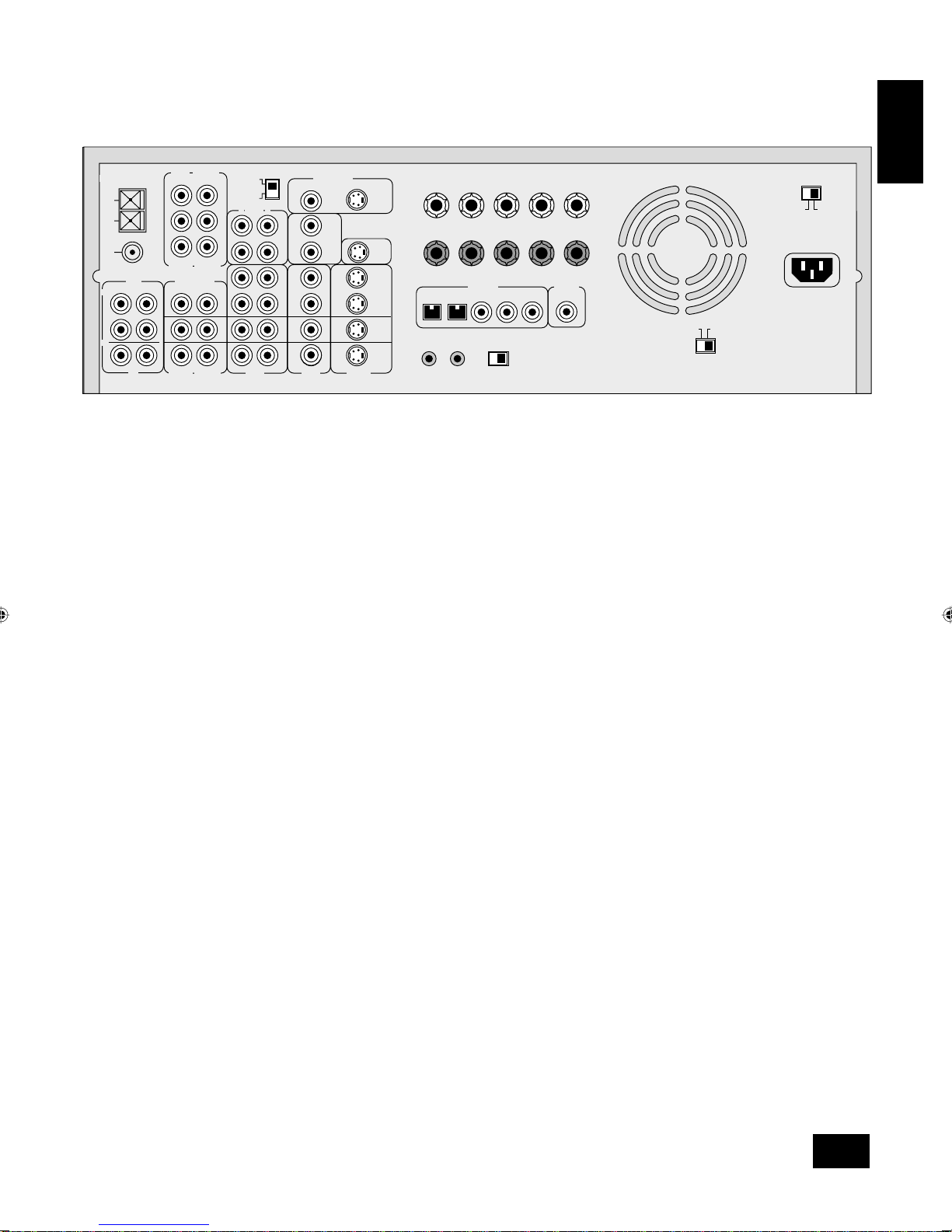
Arcam AVR200 User manual

AVR200
HANDBOOKHANDBOOK
Arcam AVR200 surround sound receiver
Ampli-tuner audiovidéo Arcam AVR200
Arcam AVR200 Surround-Sound-Empfänger
English
Français
Deutsch

AVR200
2
AVR200
2
Safety guidelines
Safety instructions
This product is designed and manufactured to meet strict
quality and safety standards. However, you should be aware of
the following installation and operation precautions:
1. Take heed of warnings and instructions
You should read all the safety and operating instructions
before operating this appliance. Retain this handbook for future
reference and adhere to all warnings in the handbook or on
the appliance.
2. Water and moisture
The presence of electricity near water can be dangerous. Do
not use the appliance near water – for example next to a
bathtub, washbowl, kitchen sink, in a wet basement or near a
swimming pool, etc.
3. Object or liquid entry
Take care that objects do not fall and liquids are not spilled into
the enclosure through any openings. Liquid filled objects such
as vases should not be placed on the equipment.
4. Ventilation
Do not place the equipment on a bed, sofa, rug or similar
soft surface, or in an enclosed bookcase or cabinet, since
ventilation may be impeded. We recommend a minimum
distance of 50mm (2 inches) around the sides and top of the
appliance to provide adequate ventilation.
5. Heat
Locate the appliance away from naked flames or heat
producing equipment such as radiators, stoves or other
appliances (including other amplifiers) that produce heat.
6. Climate
The appliance has been designed for use in moderate climates.
7. Racks and stands
Only use a rack or stand that is recommended for use with
audio equipment. If the equipment is on a portable rack it
should be moved with great care, to avoid overturning the
combination.
8. Cleaning
Unplug the unit from the mains supply before cleaning.
The case should normally only require a wipe with a soft, damp,
lint-free cloth. Do not use paint thinners or other chemical
solvents for cleaning.
We do not advise the use of furniture cleaning sprays or
polishes as they can cause indelible white marks if the unit is
subsequently wiped with a damp cloth.
9. Power sources
Only connect the appliance to a power supply of the type
described in the operating instructions or as marked on the
appliance.
10. Power-cord protection
Power supply cords should be routed so that they are not likely
to be walked on or pinched by items placed upon or against
them, paying particular attention to cords and plugs, and the
point where they exit from the appliance.
11. Grounding
Ensure that the grounding means of the appliance is not
defeated.
12. Power lines
Locate any outdoor antenna/aerial away from power lines.
13. Non-use periods
If the unit has a stand by function, a small amount of current
will continue to flow into the equipment in this mode. Unplug the
power cord of the appliance from the outlet if left unused for
a long period of time.
14. Abnormal smell
If an abnormal smell or smoke is detected from the appliance,
turn the power off immediately and unplug the unit from the wall
outlet. Contact your dealer immediately.
15. Servicing
You should not attempt to service the appliance beyond that
described in this handbook. All other servicing should be
referred to qualified service personnel.
16. Damage requiring service
The appliance should be serviced by qualified service personnel
when:
A. the power-supply cord or the plug has been damaged, or
B. objects have fallen, or liquid has spilled into the appliance,
or
C. the appliance has been exposed to rain, or
D. the appliance does not appear to operate normally or
exhibits a marked change in performance, or
E. the appliance has been dropped or the enclosure
damaged.
Safety compliance
This product has been designed to meet the EN60065
international electrical safety standard.

AVR200
3
English
Using this handbook
Manufactured under licence from Dolby Laboratories, Inc.
‘Dolby’, ‘Pro Logic’, ‘Pro Logic II’and the double-D symbol are trademarks
of Dolby Laboratories.
Copyright © 1992–1999 Dolby Laboratories, Inc. All rights reserved.
Manufactured under licence from Digital Theater Systems, Inc.
US Patent Number 5,451,942 and other world-wide patents issued and
pending. ‘DTS’and ‘DTS Digital Surround’, are trademarks of Digital
Theater Systems, Inc.
Copyright © 1996 Digital Theater Systems, Inc. All rights reserved.
Contents
Safety guidelines 2
Safety instructions 2
Safety compliance 2
Using this handbook 3
Safety 3
Installation 4
Positioning the unit 4
Setting up the aerials 4
Connecting inputs 5
AVR200 back panel connections 5
Interconnect cables 5
Connecting outputs 7
Connecting to other equipment 7
Connecting to a power supply 7
Setting up 8
Using the On Screen Display (OSD) 8
Setup page 8
Input settings page 8
Channel balance page 9
Channel delays page 9
Speaker settings page 10
Using the AVR200 12
Front panel controls 12
Input selection 12
Using the tuner 14
Tuning to a station 14
Storing a preset 14
Deleting an unused preset 14
RDS: Radio Data System 14
FM Mute/Mono 14
Using the remote control 15
CR-340 remote control 15
Reference 16
Bi-wiring and bi-amping loudspeakers 16
Before you start 16
Bi-wiring your loudspeakers 16
Bi-amping your system 16
Troubleshooting 17
Technical specifications 18
Guarantee 19
On line registration 19
This handbook has been designed to give you all the information
you need to install, connect, set up and use the Arcam AVR200
surround sound receiver. The remote control handset supplied
with the equipment is also described.
It may be that the AVR200 has been installed and set up as
part of your system installation by a qualified Arcam dealer. In
this case, you may wish to skip the sections of this handbook
dealing with installation and setting up the unit. Use the Contents
list (on this page) to guide you to the relevant sections.
Safety
Safety guidelines are set out on the inside front cover of this
handbook.
Many of these items are common sense precautions, but for
your own safety, and to ensure that you do not damage the unit,
we strongly recommend that you read them.

AVR200
4
Installation
Installation starts with positioning the unit where it can operate
effectively. To use the radio receiver, you will need to install an
FM and/or an AM aerial.
Other input signals –from CD, MD, tape, DAT, VCR, DVD, games
console or satellite receiver –will need to be connected to
sockets on the AVR200’s back panel.
Output signals –TV, monitor, projector, preamplifier,
loudspeakers, headphones or other audio or digital outputs –
also need to be connected to sockets on the back panel.
Positioning the unit
Place your AVR200 on a level, firm surface.
Avoid placing the unit in direct sunlight or near sources of heat
or damp.
Ensure adequate ventilation. Do not place the unit in an
enclosed space such as a bookcase or cabinet as both of these
will impede air flow through the ventilation slots.
Setting up the aerials
FM aerial
An FM aerial is required to receive VHF radio signals. An
external FM ribbon aerial is supplied as an accessory with the
AVR200.
For optimal FM radio reception a roof or loft mounted aerial is
advised. For your own safety it is recommended that a roof top
aerial is fitted by an experienced contractor. Your Arcam dealer
should be able to put you in contact with an aerial installer.
A contractor will be able to tune your aerial to the nearest
FM transmitter. In an apartment building an aerial system my
already be installed. If this is the case you should have sockets
in your home marked FM or VHF (do not use those marked
TV).
The ‘T’shaped wire aerial (dipole design) supplied should give
reasonably good reception. Mount this aerial as high up as
possible on a wall with the elements positioned horizontally. Try
each usable wall of the room to see which gives best reception.
Use tacks or adhesive tape to secure the aerial in a T shape.
The tacks should not come into contact with the internal wire
of the aerial.
Whether you decide to get an aerial professionally installed or
opt to use the supplied aerial it should be connected to the FM
Antenna input on the rear of the unit.
AM aerial
An AM aerial is required to receive AM/Medium Wave radio
signals.
An external AM loop aerial is supplied as an accessory with the
AVR200. This should be attached to the AM Antenna inputs with
one end connected to AM and the other to Ground. It does not
matter which way round this aerial is fitted. Rotate the aerial to
discover which position gives the best reception.
In areas of weak reception or when the receiver is used inside
a steel framed building (such as an apartment building) you
can use a wire between 3 and 5 metres long to strengthen
reception. Mount this high up outside the building, if possible,
and connect one end of this wire to the AM antenna input as
well as the loop aerial supplied. DO NOT DISCONNECT THE
LOOP AERIAL.
The AM tuning ‘step size’needs to be set according to your
location. This is done using the switch on the rear panel: set it to
10kHz if you are in North America or 9kHz anywhere else.

AVR200
5
English
Connecting inputs
AC INLET
SURROUNDLR
+
–
CENTREFRONT LR
+
–
OUT
VCR
IN
IN
DVD
IN
SAT
IN
AUX
OUT
(N.AM)10K
AM STEP
GROUND
LIFT
SPEAKER
IMPEDANCE
SELECTOR
4–6Ω8Ω
GROUND
120V 230V
LOUDSPEAKER
OUTPUTS
IN
AUX
12V
TRIGGER
OUT
REMOTE
CONTROL
INPUT
SUB
WOOFER
CENTRE AUDIO VIDEO S-VIDEO
S-VIDEO
VIDEO
AUDIO PRE-OUT
CD
TAPE 5.1 CH INPUT
SUB
WOOFER
CENTRE
IN
OUT
AUDIOR
(EU) 9K
L
LRLR
R L
FM
GND
AM
ANTENNA MONITOR OUT
FRONT SURR FRONT SURR
AUX TAPE DVD SAT CD
DIGITAL
OUT
DIGITAL IN
Interconnect cables
The use of high quality interconnect cables to and from your
AVR200 is recommended to ensure the best sound and picture
quality. Ask your Arcam dealer’s advice on cable selection.
This product does not feature a Phono input stage. If you wish
to connect a turntable to your AVR200 you will need to use
an in-line phono pre-amp. All line level inputs have the same
sensitivity so may be used with any line level source equipment,
even components other than those labelled. If you need to do
so, your Arcam dealer can give you further advice on this.
CD input
Use audio interconnects to attach the left and right audio
outputs from your CD player to the CD IN inputs on the AVR200.
If your CD player has digital output, connect it to the CD DIGITAL
IN socket on the AVR200.
TAPE loop
This input can be used to connect one of many different
recording devices, for example, a tape deck, Mini-Disc or CD-R.
Use audio interconnects to attach the left and right audio
outputs from your recorder to the corresponding TAPE inputs on
the AVR200. If your tape source has digital output, connect it to
the TAPE DIGITAL IN socket on the AVR200.
To complete the record loop, attach the left and right TAPE
outputs from the AVR200 to the corresponding record inputs
on your recorder.
5.1 channel input
This multi-channel input takes up to six (i.e. five channels plus
one sub-woofer) discrete channels of audio from a DVD audio
player or a DVD player with an integrated decoder. Use audio
interconnects to attach the DVD’s outputs to the appropriate 5.1
CH INPUT inputs on the AVR200.
For optimum performance from DVD video, however, it is usually
better to use a digital connection to the AVR200’s own internal
digital surround decoder instead.
SAT input
Use audio interconnects to attach the left and right audio
outputs from your satellite or cable receiver (or digibox) to the
corresponding SAT inputs on the AVR200.
Using either the composite or the S-video output from your
satellite receiver, connect it to the corresponding VIDEO or
S-VIDEO input on the AVR200.
If your satellite receiver provides a coaxial digital output, attach
it via the SAT digital input.
DVD input
In most cases you will achieve the best audio performance
from your DVD player by connecting its digital output to the
DVD digital input of the AVR200, using a suitable 75Ωdigital
cable. Connect either the composite or S-video output from your
DVD player to the corresponding VIDEO or S-VIDEO inputs on
the AVR200.
If you are also using your DVD player to play CDs and prefer to
use the stereo audio outputs, connect these to the CD inputs
of the AVR200.
VCR loop
Use audio interconnects to attach the left and right audio
outputs from your video cassette recorder to the VCR inputs
on the AVR200. For the video signal, use either the composite
or the S-video output from your VCR and attach to the
corresponding input on the AVR200. If the VCR has a digital
output, connect it to the VCR digital input on the AVR200.
To complete the record loop, attach the left and right VCR audio
outputs from the AVR200 to the corresponding record inputs on
your VCR. Using the same type of video connection as for the
input, connect the VCR picture output from the AVR200 to the
corresponding input on your VCR.
AUX input and record loop
Use audio interconnects to attach the left and right audio
outputs from your auxiliary source (another item of audio
equipment or a games console) to the corresponding AUX
inputs on the AVR200.
Using either the composite or the S-video output from your
auxiliary source, connect it to the corresponding VIDEO or
S-VIDEO input of the AVR200.
If your auxiliary source has a digital output, connect it to the AUX
digital input on the AVR200.

AVR200
6
GROUND LIFT switch
If your system only takes audio sources from CD or DVD,
set this switch to ‘GROUND’. In more complex setups which
involve satellite inputs or radio aerials, grounding the unit may
actually increase the level of background hum or buzz in the
loudspeakers, in which case set the switch to ‘GROUND LIFT’.
REMOTE CONTROL INPUT
This input is connected to the output of an infrared receiver. The
remote control input is usually used in custom installations. Ask
your dealer or custom installer for further details.

AVR200
7
English
Connecting to other equipment
MONITOR OUT
Both composite and S-video monitor outputs are provided for
connection to the ‘Video line in’of your TV, monitor, or projector.
If you have both Composite and S-video inputs connected to
your AVR200 you need only connect the S-VIDEO Monitor Output
to your TV (provided that your TV accepts an S-video input).
LOUDSPEAKER OUTPUTS
Before connecting loudspeakers to your AVR200 you must set
the Impedance switch on the rear to the correct position.
WARNING: Never adjust this switch with the power on
or you will damage the AVR200.
If your loudspeakers are rated at 6Ωor lower set the switch to
the 4–6Ωposition. If your loudspeakers are rated higher than
6Ω, set the switch to the 8Ωposition.
WARNING: This unit should only be used with
loudspeakers with an impedance rating between 4Ω
and 8Ω.
WARNING: When connecting loudspeakers, ensure
that no stray strands of wire are allowed to touch
other cables or the AVR200’s casing as this can cause
a short circuit and damage the amplifier.
Bi-wiring and Bi-amping loudspeakers
Notes on these techniques are given in the Reference section
of this handbook.
Preamplifier outputs
If you wish to upgrade your system by adding a power amplifier,
always specify an Arcam unit to ensure matching gain.
The AVR200 has six line-level pre-amp outputs that can be
connected to Arcam external power amplifiers to bi-amplify
(‘bi-amp’) any of the channels. Alternatively, the AVR200 can be
used solely as a preamplifier.
Depending on how your system is configured, the subwoofer
AUDIO PRE-OUT should be connected using a line level
interconnect, to either:
■an active subwoofer, or
■a power amplifier used to drive a passive subwoofer.
DIGITAL OUT
Use this socket to connect to the input of a suitable digital
recorder (e.g. a CD-R or minidisc). When using a coaxial digital
input, the signal is passed through the AVR200 with no changes.
An optical input is restricted to a maximum frequency of 48kHz.
12V TRIGGER OUT
This connection is normally used only with multi-room
installations. If you are bi-amping with a power amplifier and wish
to power both units on or off simultaneoulsy, see page 15.
PHONES (Headphone output)
A 6.3mm stereo jack socket is provided on the front panel for
headphone listening. Inserting the jack automatically mutes (i.e.
cuts off) the loudspeakers, and AUDIO PRE-OUT outputs. Surround
mode settings are ignored: headphone output is in stereo.
Connecting to a power supply
Wrong plug?
Check that the plug supplied with the unit fits your supply and
that your mains supply voltage agrees with the voltage setting
(120V or 230V) indicated on the rear panel of the unit.
If your mains supply voltage or mains plug is different, consult
your Arcam dealer or Arcam Customer Support on +44 (0)1223
203203.
Mains lead
The appliance is normally supplied with a moulded mains plug
already fitted to the lead. If for any reason the plug needs to
be removed, it must be disposed of immediately and securely,
as it is a potential shock hazard when inserted into the mains
socket. Should you require a new mains lead, contact your
Arcam dealer.
Plugging in
Push the plug (IEC line socket) of the power cable supplied with
the unit into the socket (AC INLET) in the back of the unit. Make
sure it is pushed in firmly.
Put the plug on the other end of the cable into your power
supply socket and switch the socket on.
Non-use periods
If the unit is to be left unused for an extended period, we
recommend that you switch the unit off from the front panel
button, rather than use ‘stand by’mode with the remote control.
Connecting outputs

AVR200
8
Setting up
Using the On Screen Display (OSD)
The easiest way to set up the AVR200’s multi-channel audio and
video options is through its On Screen Display (OSD).
To enter the OSD, ensure that you have a TV connected and
press any of the arrows on the remote control’s cursor pad.
To navigate from the first (i.e. Setup) page, use the
•
and
•
arrows to highlight a line. To enter a highlighted page, press OK.
To leave the OSD, highlight ‘EXIT’and press OK.
Once on a page, use the
•
and
•
arrows to move to a line
and the •and
•
arrows to change an option. Once you are
happy with the settings, highlight ‘SAVE AND EXIT’and press OK
to keep them in memory. If you are unsure about the changes,
or you have entered the page accidentally, highlight ‘DO NOT
SAVE AND EXIT’and press OK and any changes on that page
are ignored.
Setup page
The Setup page forms the index to the OSD. To navigate from
here, use the cursor pad on your remote control.
Input settings page
AUDIO Identifies the active audio source (e.g. CD)
VIDEO Identifies the active video source (e.g. DVD)
MODE Identifies the surround mode associated with
the current input (Dolby Digital, DTS, Dolby
Pro Logic II Movie, Dolby Pro Logic II Music,
Dolby Pro Logic II Panorama, Dolby Pro Logic II
Matrix, Dolby Pro Logic, Hall effect or Stereo)
DYNAMIC RANGE
A compressed dynamic range is useful for low
level (night time) listening. For Dolby Digital
sources, the dynamic range has options of
100%, 75%, 50% or 25%
CENTRE WIDTH (Dolby Pro Logic II Music Mode only)
Allows centre-channel sounds to be positioned
between the centre speaker and the left/right
speakers over a range of eight steps. Step ‘3’
uses a combination of all three front speakers
to give the best vocal imaging and most
seamless soundstage and is recommended for
most recordings. Step ‘0’places all centre
sound in the centre speaker. Step ‘7’places all
centre sound equally in the left/right speakers,
as in conventional stereo.
1 INPUT SETTINGS
2 CHANNEL BALANCE
3 CHANNEL DELAYS
4 SPEAKER SETTINGS
5 EXIT
SETUP
1 INPUT SETTINGS
2 CHANNEL BALANCE
3 CHANNEL DELAYS
4 SPEAKER SETTINGS
5 EXIT
SETUP
AUDIO = DVD
VIDEO = DVD
MODE = DOLBY DIGITAL
DYNAMIC RANGE = N/A
CENTRE WIDTH = 3
DIMENSION = 0
DO NOT SAVE AND EXIT
SAVE AND EXIT
INPUT SETTINGS
NOTE: In some cases you may find that the OSD is not still
or that it ‘rolls over’your screen. (You may also notice this
effect when the volume bar is shown on screen.) If this is
the case, you will need to switch the video system being
used by the AVR200.
To do this, first exit the OSD by highlighting EXIT and press
OK. Press and hold the STORE button on the front panel of
the AVR200 then toggle between the systems shown in the
display area by pressing the SAT button –NTSC (used in
North America) or PAL (used in most of Europe) –until the
correct system is selected.
centre
front
left front
right
20.8°20.8°
28°
36°
54°
62°
69.8°
28°36°
54°
62°
69.8°
Setting options for CENTRE WIDTH
DISPLAY EFFECT
Off No Centre spreading
1 20.8°
2 28°
3 36°
4 54°
5 62°
6 69.8°
7 Phantom Centre

AVR200
9
English
1 INPUT SETTINGS
2 CHANNEL BALANCE
3 CHANNEL DELAYS
4 SPEAKER SETTINGS
5 EXIT
SETUP
LEFT : 0dB
CENTER : 0dB
RIGHT : 0dB
REAR L : 0dB
REAR R : 0dB
SUB : 0dB
DO NOT SAVE AND EXIT
SAVE AND EXIT
CHANNEL BALANCE
NOTE: The test tone generates a noise which may not be
heard through a subwoofer. To set your sub to a suitable
level, turn off the test tone and experiment with the trim
while playing a piece of music or a movie you are familiar
with. There is no right or wrong level for the sub: simply find
the balance that is best for you.
1 INPUT SETTINGS
2 CHANNEL BALANCE
3 CHANNEL DELAYS
4 SPEAKER SETTINGS
5 EXIT
SETUP
CENTER 0ms
REAR 0ms
DO NOT SAVE AND EXIT
SAVE AND EXIT
CHANNEL DELAYS
CENTER 3ms
REAR 6ms
DO NOT SAVE AND EXIT
SAVE AND EXIT
CHANNEL DELAYS
NOTE: It is not necessary to adjust delay times separately
for a DTS (Digital Theater Systems) source.
DIMENSION (Dolby Pro Logic II Music Mode only) Allows
the gradual adjustment of the soundfield either
towards the front or the rear. This can help
achieve the desired balance from all the
speakers with certain recordings that may
contain either too much or too little spatial
effect. Step ‘0’is the recommended setting,
which has no effect on the sound. Steps
‘+1’, ‘+2’and ‘+3’gradually move the sound
forward, and steps ‘–1’, ‘–2’and ‘–3’move the
sound towards the surrounds.
Channel balance page
From the Channel balance page, you can trim the level of
each individual loudspeaker connected to the AVR200. Due to
the different performance characteristics or positioning of each
loudspeaker they may need to be set to different levels to
provide a balanced sound from the listening position. To help set
this balance, the AVR200 can generate a test tone that plays an
identical signal through each channel in turn. Trim the balance
of each speaker in turn until they all appear to produce the
same volume.
Once the channel balance page is shown in the OSD, press
the TEST button on the remote control to start the test tone.
Make sure that either Dolby Digital, Dolby Pro Logic or Dolby
Pro Logic II is selected, and that the volume on the AVR200
is set sufficiently high for the tone to be heard. The test tone
automatically cycles through each speaker channel until the
TEST button is pressed a second time.
Each loudspeaker can be trimmed between +10dB and –10dB.
You can return to the Channel balance page at any time (without
first entering the OSD) by pressing the TEST button on the
remote control. Press TEST again to exit this page.
Channel delays page
For best results in a surround sound system, the sound from
all loudspeakers should reach the listener at the same time. To
help achieve this the AVR200 can add slight delays to certain
channels when in Dolby Digital or Dolby Pro Logic modes.
When playing a Dolby Digital source you can set a delay for the
centre channel of between 0 and 5ms and a delay for the rear
channels of between 0 and 15ms.
The method of calculating these delay times is described
overleaf.
Setting options for DIMENSIONS
DISPLAY EFFECT
–3 MAX SURR Most surround
–2
–1
0 Neutral
+1
+2
+3 MAX CENTRE Most centre

AVR200
10
To calculate these delay times, first measure (or estimate)
the distances from the listening position to the front, centre
and rear speakers. Keep a record of these distances by
entering them under the heading ‘Your measurement’in the
table provided.
The centre channel delay is calculated by subtracting the centre
channel distance from the front left (or right) distance. The
difference represents the CENTRE delay time.
The rear channels’delay time is calculated by subtracting the
rear left (or right) distance from the front left (or right) distance.
The difference represents the REAR delay time. Note that if your
rear loudspeakers are further from the listening position than
the front loudspeakers, you should set this delay to 0ms.
If you have made your measurements in feet, one foot
approximates to one millisecond (1ms) delay. If you have made
your measurements in metres, one metre approximates to three
milliseconds (3ms) delay.
When playing a Dolby Pro Logic or Dolby Pro Logic II source
you can set a time delay (in milliseconds) for the rear channels.
There is no delay setting for the centre channel.
The rear channel delay in Dolby Pro Logic is calculated by
adding 15ms to the rear channel delay calculated for Dolby
Digital. In our example, this is 15ms + 6ms = 21ms.
Distance to listening position e.g. Your
measurement
Front left or right 4m or 12ft ---------------------
Centre 3m or 9ft ---------------------
Rear left or right 2m or 6ft ---------------------
Difference e.g. Delay (ms)
CENTRE delay (4 –3m) or (12 –9ft)
= 1m or 3ft 3 milliseconds
REAR delay (4 –2m) or (12 –6ft)
= 2m or 6ft 6 milliseconds
CHANNEL DELAYS
CENTER N/A
REAR 21ms
DO NOT SAVE AND EXIT
SAVE AND EXIT
e.g. 3m
(9ft)
e.g. 4m
(12ft)
e.g. 2m
(6ft)
centre
front
left front
right
rear
left rear
right

AVR200
11
English
1 INPUT SETTINGS
2 CHANNEL BALANCE
3 CHANNEL DELAYS
4 SPEAKER SETTINGS
5 EXIT
SETUP SPEAKER SETTINGS
MAIN : LARGE
CENTER : LARGE
SURROUND : LARGE
SUBWOOFER : ON
SUBWOOFER STEREO: ON
DO NOT SAVE AND EXIT
SAVE AND EXIT
Speaker settings page
The size and number of loudspeakers are defined on this page
of the OSD.
–A ‘LARGE’speaker is one that is capable of handling a full
range signal (i.e. 20Hz–20kHz).
–A ‘SMALL’speaker is one that is not capable of
reproducing a deep bass signal (i.e. below 100Hz), for
example a satellite speaker.
–‘ON’is used when a speaker is present and active and
receives the intended audio information.
–‘OFF’is used when a speaker is absent or inactive. Audio
signals intended for speakers set to OFF are redirected to
the main speakers.
Recommended speaker settings for different systems
To configure a ‘Sub/Sat’system (i.e. a set of small speakers
with a subwoofer), your speaker settings should be ‘SMALL’for
all speakers, with Subwoofer turned ‘ON’.
Some small but high performance speakers are capable of
handling a signal below 100Hz: in this instance, set them to
‘LARGE’(despite their small physical size). If in doubt, please
check the specifications in your speaker’s handbook or ask your
dealer.
If you don’t have a centre speaker, set CENTER to ‘OFF’. This
directs the centre speaker information to the front left and right
speakers, ensuring that dialogue is clearly reproduced.
The SUBWOOFER STEREO setting is only relevant for music
reproduction and does not affect sound reproduction for movies.
If you have small speakers on the front, set SUBWOOFER
STEREO to ‘ON’to give the extra bass reinforcement required
for music. If your front speakers are large, or of high quality and
performance, you may find music is reproduced more accurately
with the Subwoofer turned ‘OFF’.

AVR200
12
Using the AVR200
Front panel controls
AVR200
PHONES SAT DVD VCR AUX EXT 5.1
SURROUND
MODE TAPE
MONITOR CD FM AM BASS TREBLE
VOLUME
POWER
DIRECT
A/V SURROUND SOUND RECEIVER
RDS INFO FM MUTE/
MONO STORE PRESET/
TUNE DOWN/UP
MHz
VIDEO 1
DOLBY PL II SPEAKERS TUNED FM STEREO PRESET
MUSIC FM MUTE
POWER
Press the POWER button to turn the AVR200 on. The status LED
changes to green on powering up and the display shows the
active input. Pressing the POWER button again turns the unit and
the status LED off.
A red status LED indicates that the AVR200 is in stand by and
can be switched on by the remote handset.
Input selection
The input selection buttons are labelled to correspond with
the audio and video inputs on the rear panel of the AVR200.
To select an input, press the appropriate button on the front
panel. The audio signal for that source will then be routed to
the speakers. Any picture signal associated with that input is
switched to the monitor output.
The name of the selected input is shown in the display: SAT,
DVD, VCR or AUX, EXT 5.1, TAPE MONITOR, CD, FM and AM.
EXT 5.1
To select the source connected to the 5.1 channel input, press
EXT 5.1. When this input is selected, none of the alternative
surround modes are available.
SURROUND MODE
When a selected digital input carries a Dolby Digital or DTS
signal, the AVR200 automatically detects it and processes the
signal accordingly.
For an analogue input or when no Dolby Digital or DTS signal is
detected, pressing the SURROUND MODE button cycles through
the available surround sound modes: STEREO, PRO LOGIC II
MOVIE, PRO LOGIC II MUSIC, PRO LOGIC II PANORAMA, PRO
LOGIC II MATRIX, PRO LOGIC and HALL.
The selected mode is displayed in the main section of the
display for three seconds, before reverting to show the active
input. The surround mode continues to be shown in the left
hand side of the display. In the case of Dolby Pro Logic II, only
‘MUSIC’and ‘MOVIE’modes are illuminated.
Dolby Digital, DTS Both of these formats feature six
independent audio channels: Left, Centre,
Right, Surround Left, Surround Right
and a ‘Low Frequency Effects’(LFE) or
subwoofer channel.
Dolby Pro Logic This format decodes the centre and
surround sound signals encoded in
Dolby Surround or Dolby Stereo movie
soundtracks.
Dolby Pro Logic II This format is the next generation
in Dolby Surround decoding. It was
designed specifically to decode all
existing Dolby Surround programs with
improved spatiality and directionality.
Dolby Pro Logic II Movie is enhanced over
Dolby Pro Logic by having stereo surround
channels and no frequency filter on the
speaker signal.
Dolby Pro Logic II Music is specifically for
listening to music, not to movies.
Dolby Pro Logic II Panorama mode
extends the front stereo image to include
the surround speakers for an exciting
‘wraparound’effect with side wall imaging.
Dolby Pro Logic II Matrix is the same as
‘Music’mode, except that mono signals
are enhanced to make them seem ‘larger’.
Hall effect This format decodes a normal stereo
signal to simulate the ambience of a
concert hall.

AVR200
13
English
TAPE MONITOR
The TAPE MONITOR button selects the audio output from a
cassette deck connected to the TAPE IN phono sockets of the
AVR200. It also enables you to monitor a recording being made
on a 3-head cassette deck. Tape monitor status is shown in red
on the display.
When the tape monitor is selected, pressing other source
buttons changes the signal sent to the recorder.
CD
The CD button selects the source connected to the CD phono
sockets.
FM, AM
To select the integrated tuner function of the AVR200, press the
FM or AM button. See the section ‘Using the tuner’.
VOLUME control
To adjust the volume level of the loudspeakers, pre-amp outputs
and headphones use the VOLUME control. The volume level is
shown in the display while it is being adjusted. Three seconds
after the volume is adjusted, the display reverts to show the
selected input.
Note that different sources may require different settings of the
VOLUME control to achieve the same perceived volume level.
The volume can be controlled from 0dB over 80 steps.
BASS and TREBLE controls
Turn the bass and treble controls clockwise to boost response
or anticlockwise to cut response. For a flat response leave the
controls in the 12 o’clock ‘notched’position.
Pressing the DIRECT button bypasses the bass and treble
controls and gives a small improvement to sound quality. If
you do not wish to alter the bass or treble controls, we
recommended that you select DIRECT.
after 3 seconds
DOLBY PL II SPEAKERS VIDEO 1
dB
MUSIC
DOLBY PL II SPEAKERS VIDEO 1
MUSIC
NOTE: TAPE MONITOR is a latching button: you will need to
press it again before selecting another source for listening.

AVR200
14
RDS INFO FM MUTE/
MONO STORE PRESET/
TUNE DOWN/UP
MHz
VIDEO 1
DOLBY PL II SPEAKERS TUNED FM STEREO PRESET
MUSIC FM MUTE
Using the tuner
The AVR200’s radio tuner can be controlled from the upper row
of front panel buttons (see diagram, below) or from the remote
control handset (see ‘Using the remote control’).
Tuning to a station
Pressing the PRESET/TUNE button toggles between the two
tuning modes of the unit –‘Preset’or ‘Tune’. The selected mode
is briefly shown in the display.
Preset mode
In Preset mode, press the
•
and •buttons on the front panel
(or P–or P+ on the remote control handset) to cycle up and
down the preset stations.
See ‘Storing a preset’and ‘Deleting unused presets’, below.
Tune mode
In Tune mode:
■Press the
•
and •buttons on the front panel (or P–or
P+ on the remote control handset) for longer than half-a-
second to engage automatic tuning. The tuner searches
for a radio station signal of sufficient strength and stops.
To skip to the next station, press one of the buttons
again. Automatic tuning is available for both the FM and
AM bands.
■Tapping the
•
and •buttons engages manual tuning. This
can be used for tuning to a specific frequency. It is also
useful if you are trying to select a station that is too weak
for the auto search mode.
Regardless of the mode used to tune your AVR200, when it
is accurately tuned to a station ‘•TUNED
•
’lights up in the
display.
Storing a preset
To store a preset, tune to the radio station you wish to store.
Press the STORE button: this causes ‘MEMORY’to flash in the
display. Now select the preset number you wish to assign to
the station using the
•
and •buttons on the front panel (or
P–or P+ on the remote control handset). Press the STORE
button again.
Once the preset is stored, the display reverts to show the
station name (if RDS information is transmitted) or its frequency.
To quit the memory function without storing a preset, leave the
tuner controls untouched for ten seconds. It is also possible to
overwrite a stored station by saving another in its place. There
are thirty presets available for FM use and ten for AM use.
Your presets are retained for several weeks (but not indefinitely),
when the AVR200 is disconnected from the mains supply.
Deleting an unused preset
Press the STORE button, then select the preset number you
want to delete using the
•
and •buttons (or P–or P+ on
the remote control handset), followed by the FM MUTE/MONO
button.
The display briefly shows ‘DELETED’and ‘––’is shown in
place of the preset number. You can reactivate a deleted preset
number by storing a station in the normal way.
Radio interference
All Arcam products have been designed to very high
standards of electromagnetic compatibility.
However, both CD players and DACs generate, and can
radiate RF (radio frequency) energy. In some cases this can
cause interference with FM and AM radio reception. If this is
the case, switch the CD player off or keep the CD player and
its connecting cables as far from the tuner and its aerials as
possible. Connecting the CD player and the tuner/amplifier to
different mains sockets can also help to reduce interference.
EC COUNTRIES -–These products have been designed to
comply with directive 89/336/EEC.
USA –These products comply with FCC requirements.
RDS: Radio Data System
The Arcam AVR200 supports RDS Programme Service and RDS
Radio Text on FM broadcasts.
When a station carrying RDS information is selected ‘RDS’lights
up in the display and shortly afterwards the station’s RDS name
(e.g. ‘BBC R3’) is shown.
Press the RDS INFO button to view any RDS text information (if
a station is not transmitting text information, the display briefly
indicates ‘NO TEXT’and reverts to show the station name).
Press RDS INFO again to display the station’s frequency.
Pressing RDS INFO a third time returns you to a display of the
station name.
If the RDS INFO button is pressed while tuned to a non RDS
station, the display shows ‘NO NAME’for three seconds before
reverting to the default display.
FM Mute/Mono
The AVR200’s tuner has an auto-muting circuit that, when
engaged, mutes any signal that is of insufficient strength for
listening. To engage this circuit press the FM MUTE/MONO
button on the front panel: ‘FM MUTE’is shown in the display.
If a signal is muted you will hear no sound through the
loudspeakers.
Should you wish to listen to a station that is ‘auto muted’
press the FM MUTE/MONO button again to disengage the
muting circuit. The tuner now switches to monoaural reception,
cancelling much of the background hiss. ‘FM MUTE’is no longer
displayed and you are able to continue listening.

AVR200
15
English
MODE
CD DVD
ENTER
CD
DVD
5-1
INFO
TAPE
SAT
AV
CR-340
OK
DVD VCR AUX
CD FM AM
T
MODE
P–P+
SLEEP TEST
TRIM
CD/DVD
MODE
DYN
MODE
ENTER
CD
DVD
Using the remote control
CR-340 Remote Control
The CR-340 remote control gives access to all functions
available on the front panel, plus some additional functions
only available from the remote. It also has controls to
operate Arcam CD and DVD players.
Source selection buttons
These operate in the same way as the source selection buttons
on the front panel of your AVR200 amplifier.
RDS INFO
Displays Radio Data System (RDS) text information, if available.
Press again for station frequency, and again to show station
information (the default mode).
SLEEP
Switches the amplifier into stand by mode after a preset number
of minutes. Pressing SLEEP once will set the sleep time to 90
minutes. ‘SLEEP MODE’is shown on the display panel.
Each consecutive press of SLEEP reduces the sleep time by
30 minutes. Sleep mode is cancelled by setting the time to 0
minutes, or by pressing the POWER or STANDBY button.
TRIM
Allows direct access to trim the centre, rear and subwoofer
speaker outputs. Press TRIM to cycle between channels and use
the
•
and •arrows to adjust levels.
MODE
Scrolls through the available surround sound modes (Stereo,
Pro Logic II, etc.). The selection is shown in the display area
for three seconds.
DYNAMIC RANGE
Compresses the dynamic range for low-level listening of Dolby
Digital sources. The dynamic range may be set from 100% (the
default) to 25% (maximum compression) in steps of 25%. The
reduction is shown on the display.
CD/DVD functions
The CD/DVD button toggles the remote control unit into
controlling an Arcam CD or DVD player: this setting is briefly
confirmed by a light at the top of the controller.
VOLUME and MUTE ( )
Press +to increase volume or –to decrease the output volume
on the amplifier.
Press to mute the speaker connections and pre-amp outputs.
Both tape outputs and the headphone socket remain active. In
mute mode the display flashes ‘MUTING’.
Mute is disabled either by pressing again, or by adjusting the
volume. Note that the volume and mute controls have no effect
on the output levels of Arcam CD players.
Cursor pad and OK button
These are used to navigate through the pages in the on screen
display (OSD). See ‘Using the On Screen Display’.
TEST
Engages the test signal generator so that the volume for each
channel can be balanced from your listening position. The signal
moves from Front Left to Centre, Front Right, Rear Right, Rear
Left and Subwoofer in a continuous cycle. Note that the test
signal may not be heard through a subwoofer.
See ‘Using the On Screen Display’for full instructions on this
feature.
TUNER MODE
Toggles between Preset mode and Tune mode. See ‘Using the
tuner’for details.
P–/P+
Cycles through preset radio stations, or scans through frequency,
depending on the Tuner mode setting.
Power/Standby
Toggles the amplifier between stand by mode and full power
mode. The power indicator light next to the power button on the
front panel is red when the amplifier is in stand by and green
when powered up.
CD/DVD lights
These indicate the function of the CD/DVD button at the bottom of
the control. They are not related to any function on the AVR200.
The LED only stays on for 15 seconds to conserve battery life. If
neither LED is lit this does not mean that the remote control unit
is not working!
5.1
Selects the multi-channel output from a DVD audio player or
external decoder source connected to the 5.1 channel input.
NOTE: Remember to install the two AAA batteries
supplied before trying to use your remote control!
Do not place anything in front of the display area on the
AVR200 (where the IR receiver is located), or the remote
control may not work.

AVR200
16
Before you start
WARNING: Do not make any connections to your
amplifier while it is switched on or connected to the
mains supply.
Before switching on please check all connections
thoroughly, making sure bare wires or cables are
not touching the amplifier in the wrong places (which
could cause short circuits) and you have connected
positive (+) to positive and negative (–) to negative.
Always ensure that the volume control on your
amplifier is set to minimum before starting these
procedures.
Bi-wiring your loudspeakers
Bi-wiring improves the sound of your system because it divides
the high and low frequency signal currents into separate
speaker cables. This avoids signal distortions arising from the
high and low frequency currents interacting with one another
within a single cable, as in conventionally wired systems.
You will need:
Speakers –with four input terminals each: these will be marked
HF (High Frequency) and LF (Low Frequency).
Loudspeaker cables –two pairs of cables per loudspeaker
(which may be joined at the amplifier end if your amplifier has
only one pair of output terminals per channel). Or, a suitably
terminated cable set (a loom, probably prepared by your dealer
and capable of being used for bi-wiring in one length).
How to bi-wire loudspeakers
1. Remove the terminal links on the rear of your
loudspeakers
WARNING: This step is essential or damage to
your amplifier may result which is not covered
under warranty.
2. Connect the cables as shown in the diagram below,
ensuring correct polarity at all times.
Bi-amping your system
The performance of your system can be further enhanced over
that achieved with bi-wiring, by extending the principle one stage
further to include separate amplification for the low and high
frequency drive units in each loudspeaker enclosure.
Connect the AVR200 to the high frequency (HF) terminals
and connect your power amplifier to the low frequency (LF)
terminals.
You will need:
Speakers –with four input terminals each (as with bi-wiring):
these will be marked HF (High Frequency) and LF (Low
Frequency).
Two amplifiers –one of these would be the AVR200 and the
other an Arcam power amplifier (e.g. an P75 or P85).
Loudspeaker cables –one pair of cables per loudspeaker or
a suitably terminated cable set (a loom, probably prepared by
your dealer and capable of being used for bi-amping in one
length).
Interconnect cables –one pair of high quality interconnect
cables.
How to set up a bi-amped system
1. Remove the terminal links on the rear of your
loudspeakers.
WARNING: This step is essential or damage to
your amplifier may result which is not covered
under warranty.
2. Connect the cables as shown in the diagram below,
ensuring correct polarity at all times.
3. Use the interconnect cables to connect the AUDIO PRE-
OUT sockets of the AVR200 to the corresponding PWR
AMP IN sockets of the power amplifier.
Reference
Bi-wiring and bi-amping loudspeakers
RL
Right
speaker Left
speaker
Arcam AVR200 receiver
HF
LF
+
+
–
–
+
–
HF
LF
+
+
–
–
+
–
RL
Arcam AP85 power amplifier
+–+–
RL
Arcam AVR200 receiver
+
–
+
–
Right
speaker
HF
LF
+
–
+–
–HF
LF
+
+
–
–
Left
speaker
Bi-wiring using one set of connections on amplifier Recommended bi-amping configuration

AVR200
17
English
The following table should help you diagnose most problems that may arise when using the AVR200.
Troubleshooting
Problem
No audio
No sound on one
channel
Dolby Digital or DTS not
auto detected
Lack of bass or poor
stereo image
No sound from tuner
Remote control not
working
Picture scrolls around
screen, or picture is
only in black and white
No picture on monitor
when video source is
selected
Sound and picture
come from different
sources
AVR200 switches itself
to stand by mode
The red status LED
flashes and the AVR200
appears not to work.
Cause
1. Power Lead unplugged or not switched on
2. In stand by mode
3. Mute on
4. Tape monitor selected
1. Loudspeaker not connected or not connected properly
2. Input not connected or not connected properly
3. Speaker described as ‘OFF’in set up page
4. Channel level set too low
Digital input not connected
1. Speakers wired out of phase (i.e. +connected to –, or red
to black in error –a polarity error in one speaker)
2. Speakers set as ‘SMALL’
1. Aerial not connected properly
2. Weak signal muted by FM Mute
1. Batteries in handset fitted the wrong way round or flat
2. IR receiver window on AVR200 is obscured
3. IR receiver window flooded with light
Wrong video system selected
1. Source is not playing
2. Video connection between the source and AVR200 is not
been made
System connections made to wrong inputs of AVR200
Circuits have overheated and unit has been switched into
protection mode. This may be because airflow around the
unit is restricted.
The AVR200 has gone into protection mode. This is
probably caused by an overload or short circuit on the
loudspeaker outputs.
Solution
1. Check mains lead is connected to AVR200 and that the wall
switch is on
2. Press the POWER/STANDBY button on remote handset
3. Switch mute off
4. Press the TAPE MONITOR button
1. Check connections to AVR200 and to loudspeaker
2. Check connections to AVR200 and at source
3. Re-assign speaker settings in on-screen display
4. Re-assign channel balance in on-screen display
Connect digital output of source to appropriate input on
AVR200
1. Check all connections to AVR200 and to loudspeakers
2. Re-select preset speaker settings in on-screen display
1. Check aerial connections to AVR200’s back panel
2. Switch FM MUTE/MONO off or re-tune station
1. Check orientation of batteries/ replace discharged batteries
2. Remove obstruction
3. Move AVR200 away from light source or shade from intense
light source
To toggle between PAL and NTSC video systems, press and
hold the STORE button and click the SAT button.
1. Check and play source
2. Check system wiring: ensure connection between source
Check system wiring: ensure all connections are made to
correct input on AVR200
Switch unit off. Remove any restrictions to good airflow. Allow
unit to cool down before switching on again.
1. Turn the AVR200 off and disconnect the mains cable.
2. Check all the wiring, making sure that no bare loudspeaker
cables are touching each other or the chassis.
3. Reconnect the mains cable and switch back on.
If this does not cure the problem or the problem persists
contact your Arcam dealer.

AVR200
18
AMPLIFIER SPECIFICATION
Output power (20Hz–20kHz at 0.5%THD)
8Ω, five channels 70W
8Ω, two channels 90W
8Ω, single channel 100W
Harmonic distortion, 1W, 8Ωat 1kHz 0.02% typical
Left/right crosstalk 60dB at 1kHz
Frequency response ±1.0dB 20Hz to 20kHz
Inputs
Line inputs
sensitivity 200mV
input impedance >10kΩ
overload margin >20dB
Power amplifier input sensitivity 740mV (normal gain)
Outputs
Preamplifier
nominal output level 200mV
maximum output level 3V
Headphones
output impedance 390Ω
Physical
Dimensions W x D x H 430 x 450 x 150mm
Weight net 11.9kg
Weight packed 14.1kg
Mains voltage 230V ±12%
120V ±12%
Power consumption (maximum) 500VA
Accessories supplied Mains lead
CR-340 remote control
2 x AAA batteries
AM loop aerial
FM ribbon aerial
Technical specifications
RADIO SPECIFICATION
FM section
30 preset stations available
RDS Station Identification, Radio Data Display
FM tuning range 87.5 to 108MHz
FM sensitivity < 6µV
THD
mono < 0.25%
stereo < 0.35%
Signal/noise ratio
mono > 72dB
stereo > 66dB
Pilot tone suppression > 60dB
Alternate channel selectivity IHF > 60dB
Capture ratio < 3dB
AM section
10 preset stations available
AM tuning range
10kHz step 530 to 1710kHz
9kHz step 531 to 1602kHz
Usable sensitivity < 30µV
IF rejection > 36dB
Signal/noise ratio, 5mV input > 38dB
THD, 5mV input < 3%
E&OE
Continual improvement policy
Arcam has a policy of continual improvement for its products.
This means that designs and specifications are subject to
change without notice.
NOTE: All specification values are typical unless otherwise
stated.

AVR200
19
English
Worldwide Guarantee
This entitles you to have the unit repaired free of charge,
during the first two years after purchase, at any authorised
Arcam distributor provided that it was originally purchased from
an authorised Arcam dealer or distributor. The manufacturer
can take no responsibility for defects arising from accident,
misuse, abuse, wear and tear, neglect or through unauthorised
adjustment and/or repair, neither can they accept responsibility
for damage or loss occurring during transit to or from the
person claiming under the guarantee.
The warranty covers:
Parts and labour costs for two years from the purchase date.
After two years you must pay for both parts and labour costs.
The warranty does not cover transportation costs at any time.
Claims under guarantee
This equipment should be packed in the original packing and
returned to the dealer from whom it was purchased, or failing
this, directly to the Arcam distributor in the country of residence.
It should be sent carriage prepaid by a reputable carrier -–
NOT by post. No responsibility can be accepted for the unit
whilst in transit to the dealer or distributor and customers are
therefore advised to insure the unit against loss or damage
whilst in transit.
For further details contact Arcam at:
Arcam Customer Support Department,
Pembroke Avenue, Waterbeach, CAMBRIDGE
CB5 9PB, England.
Telephone: +44 (0)1223 203203
Fax: +44 (0)1223 863384
Problems?
If your dealer is unable to answer any query regarding this
or any other Arcam product please contact Arcam Customer
Support on +44 (0) 1223 203203 or write to us at the above
address and we will do our best to help you.
Guarantee
On line registration
You can register your Arcam product on line at:
www.arcam.co.uk/reg

AVR200
20
Normes de sécurité
Cet appareil a étéconçu et fabriquéconformément aux
normes de qualitéet de sécuritéles plus strictes. Vous devez
cependant observer les précautions suivantes lors de son
installation et de son utilisation :
1. Avertissements et consignes
Il est conseilléde lire les consignes de sécuritéet d’utilisation
avant de mettre le lecteur en marche. Conservez ce manuel
pour pouvoir vous y référer par la suite et respectez
scrupuleusement les avertissements y figurant ou ceux indiqués
sur l’appareil lui-même.
2. Eau et humidité
L’installation d’un appareil électrique àproximitéd’une source
d’eau présente de sérieux risques. Ne pas utiliser l’appareil à
proximitéd’un point d’eau - par exemple près d’une baignoire,
d’un lavabo, d’un évier, dans une cave humide ou àcôtéd’une
piscine, etc.
3. Chute d’objets ou infiltration de liquides
Veiller àne pas laisser tomber d’objets ni couler de liquides à
travers l’une des ouvertures de l’enceinte. Ne pas placer d’objet
contenant du liquide sur l’appareil.
4. Ventilation
Eviter de placer l’appareil sur un lit, un canapé, un tapis
ou une surface similaire instable, ou dans une bibliothèque
ou un meuble fermé, qui risquerait de ne pas être ventilé
correctement. Pour permettre une ventilation appropriée, il est
conseilléde prévoir au minimum un espace de 50 mm de
chaque côtéet au-dessus de l’appareil.
5. Exposition àla chaleur
Ne pas placer l’appareil près d’une flamme nue ou de tout
dispositif produisant de la chaleur (radiateur, poêle ou autre).
Cette règle s’applique également aux amplificateurs.
6. Conditions climatiques
L’appareil est conçu pour fonctionner dans des climats
modérés.
7. Etagères et supports
Utiliser uniquement des étagères ou des supports pour
équipements audio. Si l’appareil est montédans un rack de
transport, le déplacer avec précaution, pour éviter tout risque
de chute.
8. Nettoyage
Débrancher l’appareil du secteur avant de le nettoyer.
Pour le nettoyage, n’utiliser qu’un chiffon doux, humide et
non pelucheux. N’utiliser ni diluant pour peinture, ni solvant
chimique.
L’emploi de sprays ou de produits de nettoyage pour meubles
est déconseillé, car le passage d’un chiffon humide risquerait
de laisser des marques blanches indélébiles.
9. Alimentation
Brancher l’appareil uniquement àune source d’alimentation du
type mentionnédans le manuel d’utilisation ou indiquésur
l’appareil lui-même.
10. Protection des câbles d’alimentation
Veiller àce que les câbles d’alimentation ne se trouvent pas
dans un lieu de passage ou bloqués par d’autres objets. Cette
règle s’applique plus particulièrement aux prises et câbles
d’alimentation et àleurs points de sortie de l’appareil.
11. Mise àla masse
S’assurer que l’appareil est correctement mis àla masse.
12. Câbles haute tension
Eviter de monter l’antenne extérieure de l’appareil àproximitéde
câbles haute tension.
13. Périodes de non-utilisation
Si l’appareil possède une fonction de mise en veille, un léger
courant continuera de circuler lorsqu’il sera réglésur ce mode.
Débrancher le cordon d’alimentation de la prise secteur si
l’appareil doit rester inutilisépendant une période prolongée.
14. Odeur suspecte
Arrêter et débrancher immédiatement l’appareil en cas de
fumée ou d’odeur anormale. Contacter immédiatement votre
revendeur.
15. Entretien
Ne pas tenter d’effectuer d’autres opérations que celles
mentionnées dans ce manuel. Toute autre opération d’entretien
doit être effectuée par un personnel qualifié.
16. Entretien par un personnel qualifié
L’appareil doit être entretenu par un personnel qualifiélorsque :
A. le cordon d’alimentation ou la prise a étéendommagé(e),
ou
B. des objets sont tombés ou du liquide a coulédans
l’appareil, ou
C. l’appareil a étéexposéàla pluie, ou
D. l’appareil ne semble pas fonctionner normalement ou
présente des altérations dans son fonctionnement, ou
E. l’appareil est tombéou l’enceinte a étéendommagée.
Respect des consignes de sécurité
Cet appareil a étéconçu pour répondre àla norme internationale
de sécuritéélectrique EN60065.
Consignes de sécurité
Other manuals for AVR200
3
Table of contents
Languages:
Other Arcam Receiver manuals

Arcam
Arcam Solo movie 5.1 User manual

Arcam
Arcam AVR600 User manual

Arcam
Arcam AVR10 User manual

Arcam
Arcam DiVA AVR100 User manual

Arcam
Arcam AVR350 User manual

Arcam
Arcam SOLO MOVIE 2.1 User manual

Arcam
Arcam DiVA AVR300 User manual

Arcam
Arcam Solo movie User manual

Arcam
Arcam DiVA AVR300 User manual

Arcam
Arcam DiVA AVR100 Quick start guide